EP1726748A2 - Dispositif de surveillance de l'état des ferrures de poignées pour fenêtres ou portes - Google Patents
Dispositif de surveillance de l'état des ferrures de poignées pour fenêtres ou portes Download PDFInfo
- Publication number
- EP1726748A2 EP1726748A2 EP06113504A EP06113504A EP1726748A2 EP 1726748 A2 EP1726748 A2 EP 1726748A2 EP 06113504 A EP06113504 A EP 06113504A EP 06113504 A EP06113504 A EP 06113504A EP 1726748 A2 EP1726748 A2 EP 1726748A2
- Authority
- EP
- European Patent Office
- Prior art keywords
- monitoring device
- condition monitoring
- handle
- disc
- switching
- Prior art date
- Legal status (The legal status is an assumption and is not a legal conclusion. Google has not performed a legal analysis and makes no representation as to the accuracy of the status listed.)
- Granted
Links
- 238000012806 monitoring device Methods 0.000 title claims abstract description 50
- 230000033001 locomotion Effects 0.000 claims abstract description 35
- 235000014676 Phragmites communis Nutrition 0.000 claims description 20
- 230000005540 biological transmission Effects 0.000 claims description 5
- 229920003023 plastic Polymers 0.000 claims description 4
- 238000011156 evaluation Methods 0.000 claims description 3
- 238000012544 monitoring process Methods 0.000 description 3
- 238000005553 drilling Methods 0.000 description 2
- 230000000694 effects Effects 0.000 description 2
- 238000009420 retrofitting Methods 0.000 description 2
- 230000008719 thickening Effects 0.000 description 2
- 238000013519 translation Methods 0.000 description 2
- 230000014616 translation Effects 0.000 description 2
- 229910000831 Steel Inorganic materials 0.000 description 1
- 230000002411 adverse Effects 0.000 description 1
- 238000013459 approach Methods 0.000 description 1
- 238000010276 construction Methods 0.000 description 1
- 230000008878 coupling Effects 0.000 description 1
- 238000010168 coupling process Methods 0.000 description 1
- 238000005859 coupling reaction Methods 0.000 description 1
- 230000001419 dependent effect Effects 0.000 description 1
- 238000013461 design Methods 0.000 description 1
- 230000002349 favourable effect Effects 0.000 description 1
- 229920002457 flexible plastic Polymers 0.000 description 1
- 238000009434 installation Methods 0.000 description 1
- 230000009347 mechanical transmission Effects 0.000 description 1
- 239000002184 metal Substances 0.000 description 1
- 239000010959 steel Substances 0.000 description 1
- 238000009423 ventilation Methods 0.000 description 1
Images

Classifications
-
- E—FIXED CONSTRUCTIONS
- E05—LOCKS; KEYS; WINDOW OR DOOR FITTINGS; SAFES
- E05B—LOCKS; ACCESSORIES THEREFOR; HANDCUFFS
- E05B1/00—Knobs or handles for wings; Knobs, handles, or press buttons for locks or latches on wings
- E05B1/003—Handles pivoted about an axis perpendicular to the wing
-
- E—FIXED CONSTRUCTIONS
- E05—LOCKS; KEYS; WINDOW OR DOOR FITTINGS; SAFES
- E05B—LOCKS; ACCESSORIES THEREFOR; HANDCUFFS
- E05B15/00—Other details of locks; Parts for engagement by bolts of fastening devices
- E05B15/02—Striking-plates; Keepers; Bolt staples; Escutcheons
-
- E—FIXED CONSTRUCTIONS
- E05—LOCKS; KEYS; WINDOW OR DOOR FITTINGS; SAFES
- E05B—LOCKS; ACCESSORIES THEREFOR; HANDCUFFS
- E05B47/00—Operating or controlling locks or other fastening devices by electric or magnetic means
- E05B2047/0048—Circuits, feeding, monitoring
- E05B2047/0067—Monitoring
-
- E—FIXED CONSTRUCTIONS
- E05—LOCKS; KEYS; WINDOW OR DOOR FITTINGS; SAFES
- E05B—LOCKS; ACCESSORIES THEREFOR; HANDCUFFS
- E05B47/00—Operating or controlling locks or other fastening devices by electric or magnetic means
- E05B2047/0048—Circuits, feeding, monitoring
- E05B2047/0067—Monitoring
- E05B2047/0068—Door closed
-
- E—FIXED CONSTRUCTIONS
- E05—LOCKS; KEYS; WINDOW OR DOOR FITTINGS; SAFES
- E05B—LOCKS; ACCESSORIES THEREFOR; HANDCUFFS
- E05B47/00—Operating or controlling locks or other fastening devices by electric or magnetic means
- E05B2047/0094—Mechanical aspects of remotely controlled locks
-
- E—FIXED CONSTRUCTIONS
- E05—LOCKS; KEYS; WINDOW OR DOOR FITTINGS; SAFES
- E05B—LOCKS; ACCESSORIES THEREFOR; HANDCUFFS
- E05B53/00—Operation or control of locks by mechanical transmissions, e.g. from a distance
- E05B53/003—Operation or control of locks by mechanical transmissions, e.g. from a distance flexible
Definitions
- the invention relates to a condition monitoring device for handle fittings for windows or doors with a rotatable handle, wherein the state monitoring device has a movements of the handle with this mitbe termedes, sensible or switching element and a corresponding sensor or a corresponding switching element. It further relates to a handle fitting and a window or a door.
- the invention provides a condition monitoring device for handle fittings for windows or doors with a rotatable handle of the generic type, having a device - a gear - to implement the rotational movement of the handle in a linear - or substantially linear - movement of the sensible or switching element.
- the term sensible element is not narrowly defined below. Rather, it comprises both non-contact sensitive elements such as magnets, in particular permanent magnets or, for example, metallic teeth. In addition, it also comprises switching elements, e.g. Cams or the like., Which are moved past micro-switches, which can be actuated or switched by the cams.
- the movement path of the sensible element is exactly linear. But it can also describe, for example, a slight arc, the radius of which is significantly greater than the radius of a disk to be explained in more detail below about the pusher pin (s.u.).
- the subject of claim 1 leads with the simplest design means to a significantly increased switching accuracy, since it is possible by using a linearly moving switching element, the contacts or sensor elements spatially further spaced from each other than on a rotating element whose diameter due to the cramped spatial Conditions on the handle fitting can only be chosen relatively small. From this increased switching accuracy results in the desired significant increase in the switching accuracy.
- the monitoring device can be accommodated, for example, in an elongated, narrow housing, which fits well into the appearance of modern windows or doors, because it has a wide radial structure around the pusher pin waived. Especially with narrow profiles, this results in an aesthetic advantage over the visually less appealing solutions of the prior art.
- the prior art of DE 89 07452 after the realization of the invention has the disadvantage that the cooperating with a reed contact permanent magnet is in close proximity to the center of the rotary body and travels between its switching positions only a relatively small way on a circular segment. This creates circuit inaccuracies.
- the known switching device has the disadvantage that it builds up relatively high directly below the fitting to be monitored, resulting in a large amount of space.
- the invention realizes a condition monitoring device for windows and doors with a high switching accuracy and a small size, which also makes it possible to dispense with the use of a special handle part.
- the condition monitoring device according to the invention is suitable for the original equipment of windows as well as for retrofitting existing constructions.
- the switching unit consisting of a permanent magnet and a reed contact
- the switching unit By converting the direction of movement, it is possible to carry away the switching unit, consisting of a permanent magnet and a reed contact, from the direct region of the axis of the handle fitting. This allows a very low height can be realized. In addition, the switching accuracy is increased. By a relatively long linear path can also realize multiple switching contact to z. B. in a turn-tilt window, the positions "closed”, “tilted” and “rotated” to be able to scan.
- the novelty invention can be used without any change in a retrofit of the existing handle (handle fitting). As a result, the costs and installation times are reduced.
- a pivot bearing housing can be converted into linear motion in several ways.
- a flexible plastic band is arranged in a guide of a housing.
- a particular advantage is the retrofittable housing, which is designed for mounting between the handle and window profile. It is preferably designed for receiving the electrical and mechanical components of the state monitoring device and has a base plate and a one- or multi-part cover.
- a cylindrical receiving collar for receiving a disc is integrally formed on the base plate, which passes through the push-pin form-fitting manner, so that the disc rotates with the handle pin of the handle. It makes sense if a guide is formed in the base plate, in which a tape is inserted, which is displaceable in the guide.
- the guide has a circular arc surrounding the first portion, which merges tangentially into a second linear portion.
- the band is flexible and lies on its narrow side in the lead. On the band are eg
- Magnets formed in turn, e.g. be moved past reed contacts. This solution is inexpensive and yet particularly reliable.
- the invention also provides a handle fitting with a monitoring device according to one of the claims directed to this and also a window or a door with such a handle fitting.
- Both the handle fitting with the monitoring device and the monitoring device per se are commercially viable and can be used as a unit or separately, e.g. also be offered for retrofitting existing handles or existing windows or doors
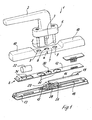
- FIG. 1 shows a handle fitting 1 with a condition monitoring device 6 according to the invention.
- FIG. 1 shows a handle fitting 1, which has a handle 2, in which a pusher pin 3 is inserted.
- Such pusher pins 3 are often pressed into the handle 2, so that they can not be replaced easily in the rule.
- the present invention therefore dispenses with this prior art measure and solves the problem Detecting the movement of the handle in an entirely different, more advantageous way.
- condition monitoring device 6 is also designed to detect a rotational movement of the handle 2. But it does not arrange the sensible or switching element on the rotating handle 2 but translates the rotational movement of the handle 2 initially via a gear 23 in a linear movement, wherein it arranges the switching or sensible element on the linearly moving component of the transmission 23. In this way, it is possible to further space the sensor elements for detecting the movement of the sensible element, namely on a straight line, rather than on a circle, which increases the monitoring accuracy.
- the mechanical transmission 23 can be realized in various ways.
- the pusher pin 3 can take a gear, which acts on a linearly displaceable rack. This solution works well (not shown here).
- the handle is rotatably mounted on a rotary bearing housing 4, which passes through the rotatable with the handle pusher pin 3 and in turn mounted on a housing or its cover 11 of the monitoring device (eg screwed), which in the region 7 for mounting the handle fitting a hole 8 for the pusher pin 3 and 9 holes for the mounting screws 5 has.
- the housing can be reduced to a very low overall height a, which is preferably only three to ten and particularly preferably five millimeters.
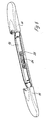
- the cover 11 may according to a preferred embodiment (Fig. 6) also formed in two parts and be divisible centrally and also cover the rotary bearing housing 4 with.
- the rotary bearing housing 4 is mounted directly on the base plate 13 in this case.
- the base plate may have side walls 24 and lateral projections or webs 25 which are undercut by guide elements (not visible here) in the interior of the two cover parts of the cover 11, so that the cover parts are pushed onto the base plate.
- This variant is on the one hand handy to handle and is characterized by a particularly attractive appearance.
- the rotary bearing housing 4 is preferably completely covered.
- the cover 11 may also be alsklippsbar on the base plate 13. This variant is particularly advantageous when a two-part cover is used, which is not held by the handle fitting.
- the base plate 13 has a round or cylindrical receptacle 14 for receiving a disk 15.
- This disc 15 in turn has a corresponding to the geometry of the pusher pin 3 opening 17, which passes through the pusher pin 3, so that the disc 15 rotates during rotation of the pusher pin 3 with this, so that the disc 15 upon actuation of the handle 2, a rotating movement performs.
- a guide 18 is formed, in which a band 16 is inserted, which is displaceable in the guide.
- the guide initially consists of the receptacle 14 and concentrically surrounds the disc 15 until it merges tangentially into a linear section.
- the disc 15 may have on at least one side a leading cylindrical projection 29 (not visible here on the underside), which engages in a pivot bearing receptacle 28 which is arranged centrally in the in the guide receptacle 14.
- two switching or detectable elements here two permanent magnets 19, are placed on the latter.
- the movement of these magnets can be sensed by one or more reed contacts 20, 21 (FIG. 4), on which the permanent magnets 19 pass during rotations of the handle 2.
- these reed contacts 20, 21 are arranged together with an evaluation circuit on the circuit board 12, which also has bores and openings 30, 31 in particular for the pusher pin 3, the screws 5 and the battery 22
- the circuit may also comprise a transmitting unit, which preferably has switching states wireless, e.g. by radio or infrared - to an external receiving unit (building management, alarm system, etc.) can send.
- a transmitting unit which preferably has switching states wireless, e.g. by radio or infrared - to an external receiving unit (building management, alarm system, etc.) can send.
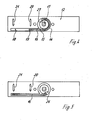
- FIGS. 4 and 5 show a schematic view of the base plate 13 and the circuit board 12.
- the guide for the attached to the outer periphery of the disc 15 band 16 can be seen well.
- the belt 16 performs during rotations of the handle and the pusher pin on the outer periphery of the disc 15, a rotating movement in the guide portion (receptacle) 14, whereby the belt 16 is moved tangentially in the guide 18.
- the elastic band 16 here has at its one end a coupling element to the disc 15, e.g. a thickening 26 which engages in a receptacle 27 on the outer circumference of the disc - and at its other end at least one or more of the permanent magnets 19th
- reed contacts 20 and 21 which are arranged in a preferred embodiment above the base plate 13 on the circuit board 12.
- the permanent magnet 19 is located at the height of the reed contact 20, which here corresponds to the "closed position of the handle.
- the disc 15 may have an external toothing and instead of the belt 16 drive a rack, to which then the permanent magnets are attached
- the individual components mentioned can be made, for example, of metal as well as of plastic.
- the band 16 and the disc 15 can be made of plastic.
- condition monitoring device can be used particularly advantageously in conjunction with window handles for turn-tilt windows.
- these turn-tilt window on three positions, which are set by a two times 90 ° rotary motion. These are the closed position (0 °), the rotary position (90 °) and the tilt position (180 °).
- the permanent magnet 19 moves off the positions "reed contact 20", “no reed contact”, “reed contact 21", which correspond to the three possible positions of the tilt and turn window.
- magnets or reed contacts can be integrated in the housing of the condition monitoring device.
Landscapes
- Burglar Alarm Systems (AREA)
- Lock And Its Accessories (AREA)
Applications Claiming Priority (1)
| Application Number | Priority Date | Filing Date | Title |
|---|---|---|---|
| DE200520008396 DE202005008396U1 (de) | 2005-05-25 | 2005-05-25 | Zustandsüberwachungseinrichtung für Griffbeschläge für Fenster oder Türen |
Publications (3)
| Publication Number | Publication Date |
|---|---|
| EP1726748A2 true EP1726748A2 (fr) | 2006-11-29 |
| EP1726748A3 EP1726748A3 (fr) | 2007-11-21 |
| EP1726748B1 EP1726748B1 (fr) | 2011-09-28 |
Family
ID=34833471
Family Applications (1)
| Application Number | Title | Priority Date | Filing Date |
|---|---|---|---|
| EP06113504A Expired - Lifetime EP1726748B1 (fr) | 2005-05-25 | 2006-05-04 | Dispositif de surveillance de l'état des ferrures de poignées pour fenêtres ou portes |
Country Status (3)
| Country | Link |
|---|---|
| EP (1) | EP1726748B1 (fr) |
| AT (1) | ATE526476T1 (fr) |
| DE (1) | DE202005008396U1 (fr) |
Cited By (3)
| Publication number | Priority date | Publication date | Assignee | Title |
|---|---|---|---|---|
| EP2998484A1 (fr) * | 2014-09-22 | 2016-03-23 | DORMA Deutschland GmbH | Armature pour une porte de bâtiment |
| EP2998468A1 (fr) * | 2014-09-22 | 2016-03-23 | DORMA Deutschland GmbH | Corps d'armature pour une armature et procédé |
| DE102017005061A1 (de) | 2017-05-26 | 2018-11-29 | Efp Vertriebs- Und Servicegesellschaft Mbh | Auswertelogik für Sensoren von Öffnungszuständen von Fenstern und Türen |
Families Citing this family (9)
| Publication number | Priority date | Publication date | Assignee | Title |
|---|---|---|---|---|
| DE102005053821B4 (de) | 2005-11-11 | 2007-07-26 | Abb Patent Gmbh | Funk-Adapter für einen Fenster- oder Türgriff |
| DE102006041744B4 (de) * | 2006-09-04 | 2009-02-26 | Elv Elektronik Ag | Fenstergriffeinheit |
| DE102007043974A1 (de) * | 2007-09-14 | 2009-03-19 | Primion Technology Ag | Türbeschlag |
| CA2770691C (fr) | 2009-08-20 | 2018-10-09 | Sargent Manufacturing Company | Dispositif de verrouillage avec carte de circuit integre |
| DE102011013730B4 (de) * | 2011-03-12 | 2013-11-28 | Heike Bedoian | Einrichtung zur Veränderung eines Verriegelungszustandes |
| DE202014006760U1 (de) | 2014-08-22 | 2015-11-24 | Siegenia-Aubi Kg | Vorrichtung zur Überwachung der Schließstellung einer Verriegelungseinrichtung |
| DE102018100578A1 (de) * | 2018-01-11 | 2019-07-11 | BSS Baumann Sicherheitssysteme GmbH | Handgriff für ein Fenster oder eine Tür und ein Alarmanlagensystem mit mehreren Handgriffen |
| CN113958199B (zh) * | 2021-10-23 | 2022-09-06 | 浙江星星冷链集成股份有限公司 | 一种基于防霉防油防碰伤结构的把手固定结构 |
| DE102024119542A1 (de) * | 2024-07-10 | 2026-01-15 | Albrecht Jung Gmbh & Co. Kg | Fenstergriffzustandsdetektionsvorrichtung, Anordnung und Verfahren mit einer solchen |
Citations (3)
| Publication number | Priority date | Publication date | Assignee | Title |
|---|---|---|---|---|
| DE8907452U1 (de) | 1989-06-19 | 1989-08-31 | BKS GmbH, 5620 Velbert | Schalteinrichtung zur elektrischen Zustandsüberwachung von Tür- oder Fensterbeschlagteilen |
| DE29603917U1 (de) | 1996-03-02 | 1996-05-09 | Buchhalter, Thomas, 53859 Niederkassel | Überwachungseinrichtung |
| US20030061849A1 (en) | 2001-10-03 | 2003-04-03 | Tsun-Tsai Yeh | Motor-driving lock |
Family Cites Families (7)
| Publication number | Priority date | Publication date | Assignee | Title |
|---|---|---|---|---|
| US1633468A (en) * | 1922-12-30 | 1927-06-21 | Yendruch John | Burglar alarm |
| US1674570A (en) * | 1927-03-07 | 1928-06-19 | Re Alfred | Alarm switch and door lock |
| SE443673B (sv) * | 1984-07-27 | 1986-03-03 | Oceanic Sa | Sensor for avkenning av positionsendringar |
| DE3915569A1 (de) * | 1989-05-12 | 1990-11-15 | Winkhaus Fa August | Fenstersystem fuer ein gebaeude |
| US6791455B2 (en) * | 2002-05-03 | 2004-09-14 | International Truck Intellectual Property Company, Llc | Vandal-lock/starter-interlock |
| DE20208183U1 (de) * | 2002-05-25 | 2002-09-12 | InPro technik GmbH, 25992 List | Vorrichtung zur Sicherung von Notausgangstüren |
| DE20315850U1 (de) * | 2003-10-15 | 2003-12-11 | Aug. Winkhaus Gmbh & Co. Kg | Schließzapfen |
-
2005
- 2005-05-25 DE DE200520008396 patent/DE202005008396U1/de not_active Expired - Lifetime
-
2006
- 2006-05-04 EP EP06113504A patent/EP1726748B1/fr not_active Expired - Lifetime
- 2006-05-04 AT AT06113504T patent/ATE526476T1/de active
Patent Citations (3)
| Publication number | Priority date | Publication date | Assignee | Title |
|---|---|---|---|---|
| DE8907452U1 (de) | 1989-06-19 | 1989-08-31 | BKS GmbH, 5620 Velbert | Schalteinrichtung zur elektrischen Zustandsüberwachung von Tür- oder Fensterbeschlagteilen |
| DE29603917U1 (de) | 1996-03-02 | 1996-05-09 | Buchhalter, Thomas, 53859 Niederkassel | Überwachungseinrichtung |
| US20030061849A1 (en) | 2001-10-03 | 2003-04-03 | Tsun-Tsai Yeh | Motor-driving lock |
Cited By (4)
| Publication number | Priority date | Publication date | Assignee | Title |
|---|---|---|---|---|
| EP2998484A1 (fr) * | 2014-09-22 | 2016-03-23 | DORMA Deutschland GmbH | Armature pour une porte de bâtiment |
| EP2998468A1 (fr) * | 2014-09-22 | 2016-03-23 | DORMA Deutschland GmbH | Corps d'armature pour une armature et procédé |
| DE102017005061A1 (de) | 2017-05-26 | 2018-11-29 | Efp Vertriebs- Und Servicegesellschaft Mbh | Auswertelogik für Sensoren von Öffnungszuständen von Fenstern und Türen |
| DE102017005061B4 (de) | 2017-05-26 | 2021-08-19 | Efp Vertriebs- Und Servicegesellschaft Mbh | Auswertelogik für Sensoren von Öffnungszuständen von Fenstern und Türen |
Also Published As
| Publication number | Publication date |
|---|---|
| EP1726748B1 (fr) | 2011-09-28 |
| EP1726748A3 (fr) | 2007-11-21 |
| DE202005008396U1 (de) | 2005-08-04 |
| ATE526476T1 (de) | 2011-10-15 |
Similar Documents
| Publication | Publication Date | Title |
|---|---|---|
| EP1726748B1 (fr) | Dispositif de surveillance de l'état des ferrures de poignées pour fenêtres ou portes | |
| EP1636454B1 (fr) | Barillet electromagnetique | |
| DE112013003564B4 (de) | Baugruppe mit elektronisch betätigtem Verriegelungsmechanismus für Schubladenschienen | |
| EP3421692B1 (fr) | Cylindre de fermeture de pommeau réglable en longueur | |
| EP3342964B1 (fr) | Dispositif de surveillance formant cadre pour fenêtres ou pour portes et fenêtre ou porte dotées du dispositif de surveillance formant cadre | |
| EP1700284B1 (fr) | Fenetre et poignee de fenetre | |
| EP1838941B1 (fr) | Dispositif pour determiner la position d'une poignee d'actionnement et/ou d'un vantail de fenetre ou de porte ou similaire | |
| DE19531680C1 (de) | Betätigungsvorrichtung | |
| EP1325479A1 (fr) | Dispositif pour determiner l'etat d'ouverture d'une porte, d'une fenetre ou similaire | |
| EP1903418B1 (fr) | Dispositif destiné à la transformation de mouvements mécaniques en signaux électriques | |
| EP1083284B1 (fr) | Dispositif de poignée de porte de véhicule pour une système de verrouillage de porte de véhicule avec fonction d'ouverture sans clef | |
| EP1785962B1 (fr) | Adaptateur radio pour poignée de fenêtre ou de porte | |
| EP0878600B1 (fr) | Dispositif d'ouverture basculante pour portes ou fenêtres actionné par un moteur électrique | |
| EP3498960B1 (fr) | Dispositif de verrouillage pour une porte, en particulier une porte coulissante | |
| EP1856354B1 (fr) | Dispositif de surveillance pour portes et fenetres | |
| EP3149263B1 (fr) | Poignée de portière pour véhicule automobile | |
| EP1302615A2 (fr) | Fenêtre ou porte avec ferrure à crémone | |
| EP1903165A2 (fr) | Poignée de fenêtre ou de porte | |
| DE3242152A1 (de) | Kofferschloss, insbesondere aktenkofferschloss | |
| EP2413341A1 (fr) | Capteur de pression pour affichage signalétique mécanique | |
| DE19628377A1 (de) | Antrieb für einen Tür- oder Fensterflügel | |
| EP1768143A2 (fr) | Charnière avec interrupteur | |
| EP1672147B1 (fr) | Poignée pour fenêtres avec des éléments fonctionnels électromécaniques | |
| DE4013994C2 (de) | Sicherheitseinrichtung zur Überwachung einer sich um eine Achse drehenden Verschlusseinrichtung | |
| EP1498648B1 (fr) | Capteur de position pour actionneur de soupape |
Legal Events
| Date | Code | Title | Description |
|---|---|---|---|
| PUAI | Public reference made under article 153(3) epc to a published international application that has entered the european phase |
Free format text: ORIGINAL CODE: 0009012 |
|
| AK | Designated contracting states |
Kind code of ref document: A2 Designated state(s): AT BE BG CH CY CZ DE DK EE ES FI FR GB GR HU IE IS IT LI LT LU LV MC NL PL PT RO SE SI SK TR |
|
| AX | Request for extension of the european patent |
Extension state: AL BA HR MK YU |
|
| PUAL | Search report despatched |
Free format text: ORIGINAL CODE: 0009013 |
|
| AK | Designated contracting states |
Kind code of ref document: A3 Designated state(s): AT BE BG CH CY CZ DE DK EE ES FI FR GB GR HU IE IS IT LI LT LU LV MC NL PL PT RO SE SI SK TR |
|
| AX | Request for extension of the european patent |
Extension state: AL BA HR MK YU |
|
| 17P | Request for examination filed |
Effective date: 20080509 |
|
| 17Q | First examination report despatched |
Effective date: 20080701 |
|
| AKX | Designation fees paid |
Designated state(s): AT BE BG CH CY CZ DE DK EE ES FI FR GB GR HU IE IS IT LI LT LU LV MC NL PL PT RO SE SI SK TR |
|
| GRAP | Despatch of communication of intention to grant a patent |
Free format text: ORIGINAL CODE: EPIDOSNIGR1 |
|
| GRAS | Grant fee paid |
Free format text: ORIGINAL CODE: EPIDOSNIGR3 |
|
| GRAA | (expected) grant |
Free format text: ORIGINAL CODE: 0009210 |
|
| AK | Designated contracting states |
Kind code of ref document: B1 Designated state(s): AT BE BG CH CY CZ DE DK EE ES FI FR GB GR HU IE IS IT LI LT LU LV MC NL PL PT RO SE SI SK TR |
|
| REG | Reference to a national code |
Ref country code: GB Ref legal event code: FG4D Free format text: NOT ENGLISH |
|
| REG | Reference to a national code |
Ref country code: CH Ref legal event code: EP Ref country code: CH Ref legal event code: NV Representative=s name: ISLER & PEDRAZZINI AG |
|
| REG | Reference to a national code |
Ref country code: IE Ref legal event code: FG4D |
|
| REG | Reference to a national code |
Ref country code: DE Ref legal event code: R096 Ref document number: 502006010256 Country of ref document: DE Effective date: 20111124 |
|
| REG | Reference to a national code |
Ref country code: NL Ref legal event code: VDEP Effective date: 20110928 |
|
| PG25 | Lapsed in a contracting state [announced via postgrant information from national office to epo] |
Ref country code: LT Free format text: LAPSE BECAUSE OF FAILURE TO SUBMIT A TRANSLATION OF THE DESCRIPTION OR TO PAY THE FEE WITHIN THE PRESCRIBED TIME-LIMIT Effective date: 20110928 Ref country code: SE Free format text: LAPSE BECAUSE OF FAILURE TO SUBMIT A TRANSLATION OF THE DESCRIPTION OR TO PAY THE FEE WITHIN THE PRESCRIBED TIME-LIMIT Effective date: 20110928 Ref country code: FI Free format text: LAPSE BECAUSE OF FAILURE TO SUBMIT A TRANSLATION OF THE DESCRIPTION OR TO PAY THE FEE WITHIN THE PRESCRIBED TIME-LIMIT Effective date: 20110928 |
|
| LTIE | Lt: invalidation of european patent or patent extension |
Effective date: 20110928 |
|
| PG25 | Lapsed in a contracting state [announced via postgrant information from national office to epo] |
Ref country code: GR Free format text: LAPSE BECAUSE OF FAILURE TO SUBMIT A TRANSLATION OF THE DESCRIPTION OR TO PAY THE FEE WITHIN THE PRESCRIBED TIME-LIMIT Effective date: 20111229 Ref country code: CY Free format text: LAPSE BECAUSE OF FAILURE TO SUBMIT A TRANSLATION OF THE DESCRIPTION OR TO PAY THE FEE WITHIN THE PRESCRIBED TIME-LIMIT Effective date: 20110928 Ref country code: LV Free format text: LAPSE BECAUSE OF FAILURE TO SUBMIT A TRANSLATION OF THE DESCRIPTION OR TO PAY THE FEE WITHIN THE PRESCRIBED TIME-LIMIT Effective date: 20110928 Ref country code: SI Free format text: LAPSE BECAUSE OF FAILURE TO SUBMIT A TRANSLATION OF THE DESCRIPTION OR TO PAY THE FEE WITHIN THE PRESCRIBED TIME-LIMIT Effective date: 20110928 |
|
| REG | Reference to a national code |
Ref country code: IE Ref legal event code: FD4D |
|
| PG25 | Lapsed in a contracting state [announced via postgrant information from national office to epo] |
Ref country code: IS Free format text: LAPSE BECAUSE OF FAILURE TO SUBMIT A TRANSLATION OF THE DESCRIPTION OR TO PAY THE FEE WITHIN THE PRESCRIBED TIME-LIMIT Effective date: 20120128 Ref country code: CZ Free format text: LAPSE BECAUSE OF FAILURE TO SUBMIT A TRANSLATION OF THE DESCRIPTION OR TO PAY THE FEE WITHIN THE PRESCRIBED TIME-LIMIT Effective date: 20110928 Ref country code: SK Free format text: LAPSE BECAUSE OF FAILURE TO SUBMIT A TRANSLATION OF THE DESCRIPTION OR TO PAY THE FEE WITHIN THE PRESCRIBED TIME-LIMIT Effective date: 20110928 |
|
| PG25 | Lapsed in a contracting state [announced via postgrant information from national office to epo] |
Ref country code: PT Free format text: LAPSE BECAUSE OF FAILURE TO SUBMIT A TRANSLATION OF THE DESCRIPTION OR TO PAY THE FEE WITHIN THE PRESCRIBED TIME-LIMIT Effective date: 20120130 Ref country code: RO Free format text: LAPSE BECAUSE OF FAILURE TO SUBMIT A TRANSLATION OF THE DESCRIPTION OR TO PAY THE FEE WITHIN THE PRESCRIBED TIME-LIMIT Effective date: 20110928 Ref country code: NL Free format text: LAPSE BECAUSE OF FAILURE TO SUBMIT A TRANSLATION OF THE DESCRIPTION OR TO PAY THE FEE WITHIN THE PRESCRIBED TIME-LIMIT Effective date: 20110928 Ref country code: EE Free format text: LAPSE BECAUSE OF FAILURE TO SUBMIT A TRANSLATION OF THE DESCRIPTION OR TO PAY THE FEE WITHIN THE PRESCRIBED TIME-LIMIT Effective date: 20110928 |
|
| PG25 | Lapsed in a contracting state [announced via postgrant information from national office to epo] |
Ref country code: IE Free format text: LAPSE BECAUSE OF FAILURE TO SUBMIT A TRANSLATION OF THE DESCRIPTION OR TO PAY THE FEE WITHIN THE PRESCRIBED TIME-LIMIT Effective date: 20110928 Ref country code: DK Free format text: LAPSE BECAUSE OF FAILURE TO SUBMIT A TRANSLATION OF THE DESCRIPTION OR TO PAY THE FEE WITHIN THE PRESCRIBED TIME-LIMIT Effective date: 20110928 |
|
| PGFP | Annual fee paid to national office [announced via postgrant information from national office to epo] |
Ref country code: CH Payment date: 20120522 Year of fee payment: 7 |
|
| PLBE | No opposition filed within time limit |
Free format text: ORIGINAL CODE: 0009261 |
|
| STAA | Information on the status of an ep patent application or granted ep patent |
Free format text: STATUS: NO OPPOSITION FILED WITHIN TIME LIMIT |
|
| PG25 | Lapsed in a contracting state [announced via postgrant information from national office to epo] |
Ref country code: PL Free format text: LAPSE BECAUSE OF FAILURE TO SUBMIT A TRANSLATION OF THE DESCRIPTION OR TO PAY THE FEE WITHIN THE PRESCRIBED TIME-LIMIT Effective date: 20110928 |
|
| PGFP | Annual fee paid to national office [announced via postgrant information from national office to epo] |
Ref country code: GB Payment date: 20120522 Year of fee payment: 7 Ref country code: FR Payment date: 20120608 Year of fee payment: 7 |
|
| 26N | No opposition filed |
Effective date: 20120629 |
|
| PGFP | Annual fee paid to national office [announced via postgrant information from national office to epo] |
Ref country code: IT Payment date: 20120524 Year of fee payment: 7 |
|
| REG | Reference to a national code |
Ref country code: DE Ref legal event code: R097 Ref document number: 502006010256 Country of ref document: DE Effective date: 20120629 |
|
| BERE | Be: lapsed |
Owner name: SCHUCO INTERNATIONAL K.G. Effective date: 20120531 |
|
| PG25 | Lapsed in a contracting state [announced via postgrant information from national office to epo] |
Ref country code: MC Free format text: LAPSE BECAUSE OF NON-PAYMENT OF DUE FEES Effective date: 20120531 |
|
| PG25 | Lapsed in a contracting state [announced via postgrant information from national office to epo] |
Ref country code: BE Free format text: LAPSE BECAUSE OF NON-PAYMENT OF DUE FEES Effective date: 20120531 |
|
| PGFP | Annual fee paid to national office [announced via postgrant information from national office to epo] |
Ref country code: AT Payment date: 20120521 Year of fee payment: 7 |
|
| PG25 | Lapsed in a contracting state [announced via postgrant information from national office to epo] |
Ref country code: ES Free format text: LAPSE BECAUSE OF FAILURE TO SUBMIT A TRANSLATION OF THE DESCRIPTION OR TO PAY THE FEE WITHIN THE PRESCRIBED TIME-LIMIT Effective date: 20120108 |
|
| PG25 | Lapsed in a contracting state [announced via postgrant information from national office to epo] |
Ref country code: BG Free format text: LAPSE BECAUSE OF FAILURE TO SUBMIT A TRANSLATION OF THE DESCRIPTION OR TO PAY THE FEE WITHIN THE PRESCRIBED TIME-LIMIT Effective date: 20111228 |
|
| REG | Reference to a national code |
Ref country code: CH Ref legal event code: PL |
|
| REG | Reference to a national code |
Ref country code: AT Ref legal event code: MM01 Ref document number: 526476 Country of ref document: AT Kind code of ref document: T Effective date: 20130531 |
|
| GBPC | Gb: european patent ceased through non-payment of renewal fee |
Effective date: 20130504 |
|
| PG25 | Lapsed in a contracting state [announced via postgrant information from national office to epo] |
Ref country code: AT Free format text: LAPSE BECAUSE OF NON-PAYMENT OF DUE FEES Effective date: 20130531 Ref country code: LI Free format text: LAPSE BECAUSE OF NON-PAYMENT OF DUE FEES Effective date: 20130531 Ref country code: CH Free format text: LAPSE BECAUSE OF NON-PAYMENT OF DUE FEES Effective date: 20130531 |
|
| PG25 | Lapsed in a contracting state [announced via postgrant information from national office to epo] |
Ref country code: IT Free format text: LAPSE BECAUSE OF NON-PAYMENT OF DUE FEES Effective date: 20130504 |
|
| REG | Reference to a national code |
Ref country code: FR Ref legal event code: ST Effective date: 20140131 |
|
| PG25 | Lapsed in a contracting state [announced via postgrant information from national office to epo] |
Ref country code: GB Free format text: LAPSE BECAUSE OF NON-PAYMENT OF DUE FEES Effective date: 20130504 Ref country code: TR Free format text: LAPSE BECAUSE OF FAILURE TO SUBMIT A TRANSLATION OF THE DESCRIPTION OR TO PAY THE FEE WITHIN THE PRESCRIBED TIME-LIMIT Effective date: 20110928 |
|
| PG25 | Lapsed in a contracting state [announced via postgrant information from national office to epo] |
Ref country code: FR Free format text: LAPSE BECAUSE OF NON-PAYMENT OF DUE FEES Effective date: 20130531 Ref country code: LU Free format text: LAPSE BECAUSE OF NON-PAYMENT OF DUE FEES Effective date: 20120504 |
|
| PG25 | Lapsed in a contracting state [announced via postgrant information from national office to epo] |
Ref country code: HU Free format text: LAPSE BECAUSE OF FAILURE TO SUBMIT A TRANSLATION OF THE DESCRIPTION OR TO PAY THE FEE WITHIN THE PRESCRIBED TIME-LIMIT Effective date: 20060504 |
|
| PGFP | Annual fee paid to national office [announced via postgrant information from national office to epo] |
Ref country code: DE Payment date: 20140606 Year of fee payment: 9 |
|
| REG | Reference to a national code |
Ref country code: DE Ref legal event code: R119 Ref document number: 502006010256 Country of ref document: DE |
|
| PG25 | Lapsed in a contracting state [announced via postgrant information from national office to epo] |
Ref country code: DE Free format text: LAPSE BECAUSE OF NON-PAYMENT OF DUE FEES Effective date: 20151201 |