EP1726811A2 - Kühlung der Klappen einer verstellbaren Schubdüse - Google Patents
Kühlung der Klappen einer verstellbaren Schubdüse Download PDFInfo
- Publication number
- EP1726811A2 EP1726811A2 EP06252768A EP06252768A EP1726811A2 EP 1726811 A2 EP1726811 A2 EP 1726811A2 EP 06252768 A EP06252768 A EP 06252768A EP 06252768 A EP06252768 A EP 06252768A EP 1726811 A2 EP1726811 A2 EP 1726811A2
- Authority
- EP
- European Patent Office
- Prior art keywords
- divergent
- cooling air
- seal
- seals
- flaps
- Prior art date
- Legal status (The legal status is an assumption and is not a legal conclusion. Google has not performed a legal analysis and makes no representation as to the accuracy of the status listed.)
- Granted
Links
Images

Classifications
-
- F—MECHANICAL ENGINEERING; LIGHTING; HEATING; WEAPONS; BLASTING
- F02—COMBUSTION ENGINES; HOT-GAS OR COMBUSTION-PRODUCT ENGINE PLANTS
- F02K—JET-PROPULSION PLANTS
- F02K1/00—Plants characterised by the form or arrangement of the jet pipe or nozzle; Jet pipes or nozzles peculiar thereto
- F02K1/06—Varying effective area of jet pipe or nozzle
- F02K1/12—Varying effective area of jet pipe or nozzle by means of pivoted flaps
- F02K1/1223—Varying effective area of jet pipe or nozzle by means of pivoted flaps of two series of flaps, the upstream series having its flaps hinged at their upstream ends on a fixed structure and the downstream series having its flaps hinged at their upstream ends on the downstream ends of the flaps of the upstream series
-
- F—MECHANICAL ENGINEERING; LIGHTING; HEATING; WEAPONS; BLASTING
- F02—COMBUSTION ENGINES; HOT-GAS OR COMBUSTION-PRODUCT ENGINE PLANTS
- F02K—JET-PROPULSION PLANTS
- F02K1/00—Plants characterised by the form or arrangement of the jet pipe or nozzle; Jet pipes or nozzles peculiar thereto
- F02K1/78—Other construction of jet pipes
- F02K1/80—Couplings or connections
- F02K1/805—Sealing devices therefor, e.g. for movable parts of jet pipes or nozzle flaps
-
- F—MECHANICAL ENGINEERING; LIGHTING; HEATING; WEAPONS; BLASTING
- F02—COMBUSTION ENGINES; HOT-GAS OR COMBUSTION-PRODUCT ENGINE PLANTS
- F02K—JET-PROPULSION PLANTS
- F02K1/00—Plants characterised by the form or arrangement of the jet pipe or nozzle; Jet pipes or nozzles peculiar thereto
- F02K1/78—Other construction of jet pipes
- F02K1/82—Jet pipe walls, e.g. liners
- F02K1/822—Heat insulating structures or liners, cooling arrangements, e.g. post combustion liners; Infrared radiation suppressors
-
- F—MECHANICAL ENGINEERING; LIGHTING; HEATING; WEAPONS; BLASTING
- F05—INDEXING SCHEMES RELATING TO ENGINES OR PUMPS IN VARIOUS SUBCLASSES OF CLASSES F01-F04
- F05D—INDEXING SCHEME FOR ASPECTS RELATING TO NON-POSITIVE-DISPLACEMENT MACHINES OR ENGINES, GAS-TURBINES OR JET-PROPULSION PLANTS
- F05D2260/00—Function
- F05D2260/20—Heat transfer, e.g. cooling
- F05D2260/202—Heat transfer, e.g. cooling by film cooling
-
- F—MECHANICAL ENGINEERING; LIGHTING; HEATING; WEAPONS; BLASTING
- F05—INDEXING SCHEMES RELATING TO ENGINES OR PUMPS IN VARIOUS SUBCLASSES OF CLASSES F01-F04
- F05D—INDEXING SCHEME FOR ASPECTS RELATING TO NON-POSITIVE-DISPLACEMENT MACHINES OR ENGINES, GAS-TURBINES OR JET-PROPULSION PLANTS
- F05D2260/00—Function
- F05D2260/20—Heat transfer, e.g. cooling
- F05D2260/205—Cooling fluid recirculation, i.e. after cooling one or more components is the cooling fluid recovered and used elsewhere for other purposes
-
- Y—GENERAL TAGGING OF NEW TECHNOLOGICAL DEVELOPMENTS; GENERAL TAGGING OF CROSS-SECTIONAL TECHNOLOGIES SPANNING OVER SEVERAL SECTIONS OF THE IPC; TECHNICAL SUBJECTS COVERED BY FORMER USPC CROSS-REFERENCE ART COLLECTIONS [XRACs] AND DIGESTS
- Y02—TECHNOLOGIES OR APPLICATIONS FOR MITIGATION OR ADAPTATION AGAINST CLIMATE CHANGE
- Y02T—CLIMATE CHANGE MITIGATION TECHNOLOGIES RELATED TO TRANSPORTATION
- Y02T50/00—Aeronautics or air transport
- Y02T50/60—Efficient propulsion technologies, e.g. for aircraft
Definitions
- Maximum thrust and operating efficiency of a gas turbine engine is achieved when the engine exhaust passes through the exhaust nozzle which controls the expansion of the exhaust gases. Maximum operating efficiency generally requires that the nozzle be configured to exit the exhaust stream at substantially the same pressure as the surrounding ambient atmosphere.
- variable throat convergent/ divergent nozzles are used to achieve proper operation for the various operating conditions.
- gas turbine engine nozzles incorporate a plurality of circumferentially arranged divergent flaps.
- Each of the divergent flaps has a "gas side", the surface of the divergent flap exposed to the exhaust gas of the engine, and an "air side", the surface of the divergent flap opposite to the gas side.
- Divergent seals are located between, and overlap, adjacent divergent flaps to prevent the escape of the exhaust gas through the gaps between the divergent flaps.
- a system for cooling lateral edge regions of an exhaust nozzle divergent seal for a gas turbine engine includes an axisymmetric nozzle having a plurality of divergent flaps disposed about a central longitudinal axis of the nozzle.
- the divergent flaps each have an inner surface defining a plurality of cooling air inlet holes at an upstream portion, a plurality of cooling air exit holes at a downstream portion, and a plurality of cooling air channels disposed within the divergent flap and communicating at a first end with the inlet holes of the divergent flap and at a second end with the exit holes of the divergent flap for conducting cooling air therethrough. At least a portion of the exit holes of the divergent flap are disposed along lateral edge regions of the divergent flap.
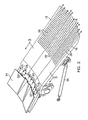
- an axisymmetric nozzle of a gas turbine engine is indicated generally by the reference number 10.
- the nozzle 10 comprises a plurality of convergent flaps 12 and convergent seals 14 disposed about a central longitudinal axis of the nozzle.
- the nozzle 10 further comprises a plurality of divergent flaps 16 and divergent seals 18 disposed about the central longitudinal axis.
- the convergent flaps 12 and the divergent flaps 16 are movably adjusted by actuation linkages 20 interiorly disposed within the nozzle 10.
- the nozzle 10 includes a plurality of external flaps 22 on a one-to-one basis with the divergent flaps 16, located outboard of and surrounding the nozzle 10.
- the external flaps 22 protect the internal mechanism of the nozzle 10 and provide a smoother appearance.
- the external flaps 22 also provide a proper aerodynamic exterior so as to avoid cracks or openings which could induce flow perturbations.
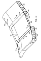
- FIG. 2 is an enlarged view of a portion of the nozzle 10 showing in greater detail a divergent seal 18 disposed between two adjacent divergent flaps 16.
- the divergent flaps 16 and the divergent seals 18 each define a plurality of cooling air inlet holes 24 at an upstream end, and each define a plurality of cooling air exit holes 26 defined at a downstream end.
- each of the divergent flaps 16 defines a plurality of inner channels 28, and each of the divergent seals 18 defines a plurality of inner channels 30.
- Each of the channels 28, 30 associated with the divergent flaps 16 and the divergent seals 18 communicates at a first end with a portion of the inlet holes 24 and communicates at a second end with a portion of the exit holes 26.
- a portion of cooling air discharge 32 from nozzle convergent liners 34 is diverted into the inlet holes 24, through the channels 28 of the divergent flaps 16 and the channels 30 of the divergent seals 18, and out of the exit holes 26 to more effectively cool the gas path surfaces of the divergent flaps and the divergent seals during engine augmentation.
- the inlet holes 24 defined in the upstream end of the divergent flaps 16 and the divergent seals 18, and the exit holes 26 defined in the downstream end of the divergent flaps and the divergent seals provide a means for cooling air to be routed through the channels 28, 30 formed preferably by a sheet metal construction of these parts.
- the channels 28, 30 form a plenum in which the inlet and exit holes 24, 26 defined in hot sheets forming the divergent flaps 16 and the divergent seals 18 provide the discharge of cooling air to actively film and effusion cool the gas path surfaces.
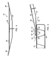
- cooling air is routed to effectively cool lateral edge regions 36 of the divergent seals 18.
- the divergent flaps 16 define cooling air exit holes 26 disposed adjacent to lateral edge regions 38 thereof.
- the lateral edge regions 36 of the divergent seals 18 each have an outer backside surface which is in overlying relationship with at least a portion of the cooling air exit holes 26 defined in an associated adjacent divergent flap 16 throughout the entire augmented range of motion of the nozzle 10.
Landscapes
- Engineering & Computer Science (AREA)
- Chemical & Material Sciences (AREA)
- Combustion & Propulsion (AREA)
- Mechanical Engineering (AREA)
- General Engineering & Computer Science (AREA)
- Turbine Rotor Nozzle Sealing (AREA)
Applications Claiming Priority (1)
| Application Number | Priority Date | Filing Date | Title |
|---|---|---|---|
| US11/140,667 US7377099B2 (en) | 2005-05-27 | 2005-05-27 | System and method for cooling lateral edge regions of a divergent seal of an axisymmetric nozzle |
Publications (3)
| Publication Number | Publication Date |
|---|---|
| EP1726811A2 true EP1726811A2 (de) | 2006-11-29 |
| EP1726811A3 EP1726811A3 (de) | 2010-06-16 |
| EP1726811B1 EP1726811B1 (de) | 2013-03-06 |
Family
ID=36649439
Family Applications (1)
| Application Number | Title | Priority Date | Filing Date |
|---|---|---|---|
| EP06252768A Active EP1726811B1 (de) | 2005-05-27 | 2006-05-26 | Kühlung der Klappen einer verstellbaren Schubdüse |
Country Status (3)
| Country | Link |
|---|---|
| US (1) | US7377099B2 (de) |
| EP (1) | EP1726811B1 (de) |
| JP (1) | JP2006329201A (de) |
Cited By (3)
| Publication number | Priority date | Publication date | Assignee | Title |
|---|---|---|---|---|
| EP1961944A3 (de) * | 2007-02-20 | 2012-07-25 | United Technologies Corporation | Konvergente-divergente Düse mit schachtgekühlter Düsenauskleidung |
| EP2546505A3 (de) * | 2011-07-14 | 2014-08-27 | Rolls-Royce plc | Abgasdüse für Gasturbinenmotor |
| CN110259599A (zh) * | 2013-10-07 | 2019-09-20 | 罗尔公司 | 具有金属和复合构造的混合式内部固定结构 |
Families Citing this family (11)
| Publication number | Priority date | Publication date | Assignee | Title |
|---|---|---|---|---|
| US8201413B2 (en) | 2006-07-24 | 2012-06-19 | United Technologies Corporation | Seal land with air injection for cavity purging |
| US7555904B1 (en) * | 2006-09-29 | 2009-07-07 | United Technologies Corporation | Thermally compliant rivet connection for connecting turbine engine liner to convergent flap and seal for turbine nozzle |
| US8205454B2 (en) * | 2007-02-06 | 2012-06-26 | United Technologies Corporation | Convergent divergent nozzle with edge cooled divergent seals |
| US8322127B2 (en) * | 2007-11-01 | 2012-12-04 | United Technologies Corporation | Nozzle assembly with flow conduits |
| US8607577B2 (en) * | 2009-11-24 | 2013-12-17 | United Technologies Corporation | Attaching ceramic matrix composite to high temperature gas turbine structure |
| US9932845B2 (en) * | 2011-06-30 | 2018-04-03 | United Technologies Corporation | Impingement cooled nozzle liner |
| EP3036422B1 (de) | 2013-08-23 | 2023-04-12 | Raytheon Technologies Corporation | Hochleistungsfähige konvergent-divergente düse |
| EP3097301B1 (de) * | 2014-01-24 | 2018-05-02 | United Technologies Corporation | Divergenzklappe |
| US10012104B2 (en) | 2014-10-14 | 2018-07-03 | United Technologies Corporation | Gas turbine engine convergent/divergent nozzle with unitary synchronization ring for roller track nozzle |
| CN113623084B (zh) * | 2021-10-13 | 2022-02-01 | 中国航发四川燃气涡轮研究院 | 一种适用二元矢量喷管排气系统的高效组合冷却结构 |
| CN114151227B (zh) * | 2021-10-20 | 2023-05-05 | 中国航发四川燃气涡轮研究院 | 一种用于二元矢量喷管的隔热屏结构 |
Family Cites Families (17)
| Publication number | Priority date | Publication date | Assignee | Title |
|---|---|---|---|---|
| US2989845A (en) * | 1957-12-02 | 1961-06-27 | Curtiss Wright Corp | Converging-diverging nozzle construction |
| US4081137A (en) * | 1977-01-05 | 1978-03-28 | The United States Of America As Represented By The Secretary Of The Air Force | Finned surface cooled nozzle |
| US4544098A (en) | 1982-12-27 | 1985-10-01 | United Technologies Corporation | Cooled exhaust nozzle flaps |
| US4662566A (en) | 1985-12-02 | 1987-05-05 | United Technologies Corporation | Louvered seal flap for flap-type nozzle |
| US5082182A (en) | 1990-08-23 | 1992-01-21 | United Technologies Corporation | Thrust vectoring exhaust nozzle |
| US5261605A (en) | 1990-08-23 | 1993-11-16 | United Technologies Corporation | Axisymmetric nozzle with gimbled unison ring |
| US5141154A (en) | 1991-04-22 | 1992-08-25 | United Technologies Corporation | Variable throat convergent/divergent nozzle |
| US5720434A (en) * | 1991-11-05 | 1998-02-24 | General Electric Company | Cooling apparatus for aircraft gas turbine engine exhaust nozzles |
| US5215257A (en) | 1992-07-16 | 1993-06-01 | United Technologies Corporation | Divergent seal arrangement for a convergent/divergent nozzle |
| US5238189A (en) | 1992-07-16 | 1993-08-24 | United Technologies Corporation | Convergent-to-divergent seal hinge for a convergent/divergent nozzle |
| US5232158A (en) | 1992-08-11 | 1993-08-03 | United Technologies Corporation | Convergent/divergent nozzle with seal centering |
| US5285637A (en) | 1992-11-02 | 1994-02-15 | United Technologies Corporation | Seal centering and restraining device for an axisymmetric convergent/divergent nozzle |
| US5364029A (en) | 1993-08-30 | 1994-11-15 | United Technologies Corporation | Axisymmetric convergent/divergent nozzle with external flaps |
| US5511376A (en) | 1993-08-31 | 1996-04-30 | United Technologies Corporation | Axisymmetric vectoring nozzle |
| US6779336B2 (en) * | 2002-07-05 | 2004-08-24 | United Technologies Corporation | Cooled variable geometry exhaust nozzle |
| FR2858833B1 (fr) * | 2003-08-12 | 2006-01-06 | Snecma Moteurs | Tuyere convergente divergente du turboreacteur |
| US7032835B2 (en) * | 2004-01-28 | 2006-04-25 | United Technologies Corporation | Convergent/divergent nozzle with modulated cooling |
-
2005
- 2005-05-27 US US11/140,667 patent/US7377099B2/en active Active
-
2006
- 2006-05-26 EP EP06252768A patent/EP1726811B1/de active Active
- 2006-05-29 JP JP2006147672A patent/JP2006329201A/ja active Pending
Non-Patent Citations (1)
| Title |
|---|
| None |
Cited By (4)
| Publication number | Priority date | Publication date | Assignee | Title |
|---|---|---|---|---|
| EP1961944A3 (de) * | 2007-02-20 | 2012-07-25 | United Technologies Corporation | Konvergente-divergente Düse mit schachtgekühlter Düsenauskleidung |
| EP2546505A3 (de) * | 2011-07-14 | 2014-08-27 | Rolls-Royce plc | Abgasdüse für Gasturbinenmotor |
| US9145846B2 (en) | 2011-07-14 | 2015-09-29 | Rolls-Royce Plc | Gas turbine engine exhaust nozzle including a plurality of flaps movable over a flow control surface |
| CN110259599A (zh) * | 2013-10-07 | 2019-09-20 | 罗尔公司 | 具有金属和复合构造的混合式内部固定结构 |
Also Published As
| Publication number | Publication date |
|---|---|
| EP1726811B1 (de) | 2013-03-06 |
| EP1726811A3 (de) | 2010-06-16 |
| JP2006329201A (ja) | 2006-12-07 |
| US20060266016A1 (en) | 2006-11-30 |
| US7377099B2 (en) | 2008-05-27 |
Similar Documents
| Publication | Publication Date | Title |
|---|---|---|
| US4544098A (en) | Cooled exhaust nozzle flaps | |
| EP0992654B1 (de) | Kühlungsöffnungen für Gasturbinenkomponenten | |
| EP2971723B1 (de) | Gasturbinenmotor mit dreistromschwenkdüse mit variablem bereich | |
| US7032835B2 (en) | Convergent/divergent nozzle with modulated cooling | |
| EP1726811B1 (de) | Kühlung der Klappen einer verstellbaren Schubdüse | |
| EP1892405B1 (de) | Abgaskanalbelüftung für ein Gasturbinentriebwerk | |
| US9097140B2 (en) | Cavity ventilation | |
| MXPA05004420A (es) | Ducto de transicion enfriado por efusion con agujeros de enfriamiento configurados. | |
| EP2691610B1 (de) | Kühlluftleitelement in einer gasturbinenbrennkammer | |
| US20050268613A1 (en) | Method and apparatus for cooling combustor liner and transition piece of a gas turbine | |
| US7484355B2 (en) | Thrust reverser comprising optimized deflector gratings | |
| EP2236750B1 (de) | Agencement de refroidissement par projection pour moteur à turbine à gaz | |
| US9777636B2 (en) | Turbine case cooling system | |
| EP3591294B1 (de) | Anordnung für einen gasturbinenmotor mit einer brennkammerwandung und einer hinteren dichtung | |
| EP2375160A2 (de) | Kühlsystem mit abgewinkelter Dichtung | |
| EP2959146B1 (de) | Mantelstrom-triebwerk mit dritter strömungswegausstromdüse | |
| EP1378651B1 (de) | Gekühlte Schubdüse mit variabler Geometrie | |
| US5141154A (en) | Variable throat convergent/divergent nozzle | |
| US11293347B2 (en) | Airfoil with baffle showerhead and cooling passage network having aft inlet | |
| EP3584409B1 (de) | Turbinenschaufel mit minikernkanal mit geneigter diffusoröffnung | |
| US12000358B1 (en) | Gas turbine engine nozzle loft for thrust reverser | |
| CA2495166C (en) | Axisymmetric flap on gas turbine exhaust centerbody |
Legal Events
| Date | Code | Title | Description |
|---|---|---|---|
| PUAI | Public reference made under article 153(3) epc to a published international application that has entered the european phase |
Free format text: ORIGINAL CODE: 0009012 |
|
| AK | Designated contracting states |
Kind code of ref document: A2 Designated state(s): AT BE BG CH CY CZ DE DK EE ES FI FR GB GR HU IE IS IT LI LT LU LV MC NL PL PT RO SE SI SK TR |
|
| AX | Request for extension of the european patent |
Extension state: AL BA HR MK YU |
|
| PUAL | Search report despatched |
Free format text: ORIGINAL CODE: 0009013 |
|
| AK | Designated contracting states |
Kind code of ref document: A3 Designated state(s): AT BE BG CH CY CZ DE DK EE ES FI FR GB GR HU IE IS IT LI LT LU LV MC NL PL PT RO SE SI SK TR |
|
| AX | Request for extension of the european patent |
Extension state: AL BA HR MK YU |
|
| 17P | Request for examination filed |
Effective date: 20101213 |
|
| AKX | Designation fees paid |
Designated state(s): DE FR GB |
|
| GRAP | Despatch of communication of intention to grant a patent |
Free format text: ORIGINAL CODE: EPIDOSNIGR1 |
|
| GRAP | Despatch of communication of intention to grant a patent |
Free format text: ORIGINAL CODE: EPIDOSNIGR1 |
|
| GRAS | Grant fee paid |
Free format text: ORIGINAL CODE: EPIDOSNIGR3 |
|
| GRAA | (expected) grant |
Free format text: ORIGINAL CODE: 0009210 |
|
| AK | Designated contracting states |
Kind code of ref document: B1 Designated state(s): DE FR GB |
|
| REG | Reference to a national code |
Ref country code: GB Ref legal event code: FG4D Ref country code: DE Ref legal event code: R081 Ref document number: 602006034879 Country of ref document: DE Owner name: UNITED TECHNOLOGIES CORP. (N.D.GES.D. STAATES , US Free format text: FORMER OWNER: UNITED TECHNOLOGIES CORP. (N.D.GES.D. STAATES DELAWARE), HARTFORD, CONN., US |
|
| REG | Reference to a national code |
Ref country code: DE Ref legal event code: R096 Ref document number: 602006034879 Country of ref document: DE Effective date: 20130502 |
|
| PLBE | No opposition filed within time limit |
Free format text: ORIGINAL CODE: 0009261 |
|
| STAA | Information on the status of an ep patent application or granted ep patent |
Free format text: STATUS: NO OPPOSITION FILED WITHIN TIME LIMIT |
|
| 26N | No opposition filed |
Effective date: 20131209 |
|
| REG | Reference to a national code |
Ref country code: FR Ref legal event code: ST Effective date: 20140131 |
|
| REG | Reference to a national code |
Ref country code: DE Ref legal event code: R097 Ref document number: 602006034879 Country of ref document: DE Effective date: 20131209 |
|
| PG25 | Lapsed in a contracting state [announced via postgrant information from national office to epo] |
Ref country code: FR Free format text: LAPSE BECAUSE OF NON-PAYMENT OF DUE FEES Effective date: 20130531 |
|
| REG | Reference to a national code |
Ref country code: DE Ref legal event code: R082 Ref document number: 602006034879 Country of ref document: DE Representative=s name: SCHMITT-NILSON SCHRAUD WAIBEL WOHLFROM PATENTA, DE |
|
| REG | Reference to a national code |
Ref country code: DE Ref legal event code: R082 Ref document number: 602006034879 Country of ref document: DE Representative=s name: SCHMITT-NILSON SCHRAUD WAIBEL WOHLFROM PATENTA, DE Ref country code: DE Ref legal event code: R081 Ref document number: 602006034879 Country of ref document: DE Owner name: UNITED TECHNOLOGIES CORP. (N.D.GES.D. STAATES , US Free format text: FORMER OWNER: UNITED TECHNOLOGIES CORPORATION, HARTFORD, CONN., US |
|
| PGFP | Annual fee paid to national office [announced via postgrant information from national office to epo] |
Ref country code: DE Payment date: 20190418 Year of fee payment: 14 |
|
| REG | Reference to a national code |
Ref country code: DE Ref legal event code: R119 Ref document number: 602006034879 Country of ref document: DE |
|
| PG25 | Lapsed in a contracting state [announced via postgrant information from national office to epo] |
Ref country code: DE Free format text: LAPSE BECAUSE OF NON-PAYMENT OF DUE FEES Effective date: 20201201 |
|
| PGFP | Annual fee paid to national office [announced via postgrant information from national office to epo] |
Ref country code: GB Payment date: 20250423 Year of fee payment: 20 |