EP1726848A2 - Tendeur pour mettre sous tension simultanément plusieurs lingots - Google Patents
Tendeur pour mettre sous tension simultanément plusieurs lingots Download PDFInfo
- Publication number
- EP1726848A2 EP1726848A2 EP06005610A EP06005610A EP1726848A2 EP 1726848 A2 EP1726848 A2 EP 1726848A2 EP 06005610 A EP06005610 A EP 06005610A EP 06005610 A EP06005610 A EP 06005610A EP 1726848 A2 EP1726848 A2 EP 1726848A2
- Authority
- EP
- European Patent Office
- Prior art keywords
- tensioner
- chain
- piston
- arms
- link
- Prior art date
- Legal status (The legal status is an assumption and is not a legal conclusion. Google has not performed a legal analysis and makes no representation as to the accuracy of the status listed.)
- Withdrawn
Links
- 238000000034 method Methods 0.000 claims 5
- 230000009191 jumping Effects 0.000 description 2
- 230000005540 biological transmission Effects 0.000 description 1
- 239000012530 fluid Substances 0.000 description 1
- 229910052751 metal Inorganic materials 0.000 description 1
Images




Classifications
-
- F—MECHANICAL ENGINEERING; LIGHTING; HEATING; WEAPONS; BLASTING
- F16—ENGINEERING ELEMENTS AND UNITS; GENERAL MEASURES FOR PRODUCING AND MAINTAINING EFFECTIVE FUNCTIONING OF MACHINES OR INSTALLATIONS; THERMAL INSULATION IN GENERAL
- F16H—GEARING
- F16H7/00—Gearings for conveying rotary motion by endless flexible members
- F16H7/08—Means for varying tension of belts, ropes or chains
-
- F—MECHANICAL ENGINEERING; LIGHTING; HEATING; WEAPONS; BLASTING
- F16—ENGINEERING ELEMENTS AND UNITS; GENERAL MEASURES FOR PRODUCING AND MAINTAINING EFFECTIVE FUNCTIONING OF MACHINES OR INSTALLATIONS; THERMAL INSULATION IN GENERAL
- F16H—GEARING
- F16H7/00—Gearings for conveying rotary motion by endless flexible members
- F16H7/08—Means for varying tension of belts, ropes or chains
- F16H2007/0802—Actuators for final output members
- F16H2007/0806—Compression coil springs
-
- F—MECHANICAL ENGINEERING; LIGHTING; HEATING; WEAPONS; BLASTING
- F16—ENGINEERING ELEMENTS AND UNITS; GENERAL MEASURES FOR PRODUCING AND MAINTAINING EFFECTIVE FUNCTIONING OF MACHINES OR INSTALLATIONS; THERMAL INSULATION IN GENERAL
- F16H—GEARING
- F16H7/00—Gearings for conveying rotary motion by endless flexible members
- F16H7/08—Means for varying tension of belts, ropes or chains
- F16H2007/0802—Actuators for final output members
- F16H2007/0812—Fluid pressure
-
- F—MECHANICAL ENGINEERING; LIGHTING; HEATING; WEAPONS; BLASTING
- F16—ENGINEERING ELEMENTS AND UNITS; GENERAL MEASURES FOR PRODUCING AND MAINTAINING EFFECTIVE FUNCTIONING OF MACHINES OR INSTALLATIONS; THERMAL INSULATION IN GENERAL
- F16H—GEARING
- F16H7/00—Gearings for conveying rotary motion by endless flexible members
- F16H7/08—Means for varying tension of belts, ropes or chains
- F16H7/0848—Means for varying tension of belts, ropes or chains with means for impeding reverse motion
- F16H2007/0853—Ratchets
-
- F—MECHANICAL ENGINEERING; LIGHTING; HEATING; WEAPONS; BLASTING
- F16—ENGINEERING ELEMENTS AND UNITS; GENERAL MEASURES FOR PRODUCING AND MAINTAINING EFFECTIVE FUNCTIONING OF MACHINES OR INSTALLATIONS; THERMAL INSULATION IN GENERAL
- F16H—GEARING
- F16H7/00—Gearings for conveying rotary motion by endless flexible members
- F16H7/08—Means for varying tension of belts, ropes or chains
- F16H2007/0863—Finally actuated members, e.g. constructional details thereof
- F16H2007/0874—Two or more finally actuated members
Definitions
- the invention pertains to the field of tensioners. More particularly, the invention pertains to a tensioner that simultaneously tensions multiple strands of the chain.
- Chain tensioners in engines are used to control the power transmission chains as the chain travels around a plurality of sprockets.
- the slack of the chain varies as the temperature in an engine increases and as the chain wears. When a chain wears, the chain elongates and the slack in the chain increase. The increase in slack may cause noise, slippage, or tooth jumping between the chain and the sprocket teeth. If the increase of the slack of the chain is not taken up, by a tensioner for example in an engine with a chain driven camshaft, the engine may be damaged because the camshaft timing is misaligned by several degrees due to slippage or tooth jumping.
- a tensioner that tensions multiple strands is US Patent No. 6,322,470 .
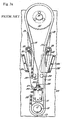
- a chain 114 is wrapped around a drive sprocket 110 and a driven sprocket 112 as shown in prior art Figure 1.
- the tensioner system includes a pivoting lever 130 which carries a pair of arms 160, 161 with shoes 170, 171.
- the pivoting lever 130 has first end 131 that is circular and aligned along a centerline C between the strands of the chain.
- the pivoting lever 130 pivots 125 in a counterclockwise direction D about the first end 131.
- the second end 134 of the pivoting lever 130 extends outside of the chain strands and has a contact surface 135 that extends perpendicular to the lever 130 and receives a plunger 120 of an actuator 116.
- the arms 160, 161 are fixedly attached to lever 130 by pins 136, 137 slightly left and right of the centerline respectively. Movement of the lever 130 causes the fixed pins 136, 137 to move equally in the lateral direction.
- the plunger 120 moves the second end 134 of the lever 130 in direction D and pivots about pin 125, which causes a counterclockwise movement of the first end 131 of the lever 130.
- the fixed pins 136, 137 pull the arms 160, 161 with shoes 170, 171 laterally toward the chain centerline C, and into contact with the outside portion of the strands of the chain.
- the chain is tightened from both sides equally.
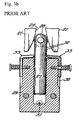
- Figure 2a shows the tensioner 210 of US Patent No. 6,312,351 in the retracted position biasing a blade arm 201.
- Figure 2b shows the tensioner 210 in an extended position biasing a blade arm 201.
- Figure 2c shows the tensioner 210.
- Oil is introduced to a chamber 202 formed between the piston 204 and the housing 230 through a check valve 206.
- the oil in the chamber 202 and a spring 203 bias the piston 204 to protrude from the housing 230 and bias the blade arm 201.
- the housing 230 is pivotally connected to the engine block.
- Figure 3a shows a tensioner from US Patent No. 2,210,276 .
- a chain 13 is wrapped around a crankshaft sprocket 12 mounted on the crankshaft 11 and a camshaft sprocket 14 mounted on the camshaft 10.
- the chain has a drive stretch 15 and a slack stretch 16.
- the shoes 17, 18 are pivoted at point 20 to the upper ends of levers 21 which are pivoted at point 22 to the engine block 23.
- a guide yoke 24 secured to the engine block 23, is arranged at the upper end of levers 21 to retain them in the proper plane of movement.
- the lower ends of the levers 21 have cammed surfaces 26.
- the levers 21 may pivot about points 22 such that the shoes 17, 18 are moved toward each other by a fluid motor comprising a piston 27, the upper end which carries a roller 28 that engages the cammed surfaces of the levers 21.
- the piston fits in a cylinder 29 and is biased outwards by oil from the oil port 31. When oil pressure drops to zero, the oil pressure supporting the piston is withdrawn, and pawls 33 positioned in channeled grooves 38 of the cylinder 29 engage ratchet teeth 32 on the piston 27 as shown in Figure 3b.
- the chain followers 17, 18 and levers 21 are not directly connected to each other.
- US Patent No. 2,129,107 discloses a tensioner for a chain with two arms biasing the chain inwards.
- Each arm includes a metallic element and a shoe.
- One end of the arm is pivotally attached to a linkage piece, which is pivotally attached to the engine frame.
- the opposite end of the arm is biased by a hydraulic shoe positioning member.
- the two arms are not directly connected to each other.
- US Patent No. 5,702,318 discloses a pair of levers that are interconnected and fixed at one end to the same rotatable base.
- One of the levers has a convexly curved surface that touches the internal portion of one strand of the chain and is biased by a tensioner.
- the other lever is also convexly curved and is disposed on the external side of the same strand of the chain. Any force from the tensioner imparted on the first lever also moves the second lever.
- US Patent Application Publication No. 2003/0153420 discloses a tensioner with two arms coupled at a first end to a resilient drive and at a second end to a rotatable pulley.
- the arms are positioned within the pulley to maintain a constant angle between them.
- the first arm is positioned to form a negative differential angle with respect to the belt and the second arm is positioned to form a positive differential angle with respect to the belt.
- a tensioner system imparting tension to a chain comprising a pair of tensioner arms, at least one link piece, and a tensioner.
- the pair of tensioner arms have a pivoting end for rotation about a fixed pin, a link end, and a shoe with a chain sliding face.
- At least one link piece has a first end pivotally attached to the link end of each of the tensioner arms.
- the tensioner has a housing for receiving a piston having an end encompassing a pin that joins the second end of the link pieces together. When the piston of the tensioner is biased outwards from the housing, the end of the piston contacts the pin joining the link pieces of the tensioner arms, moving the tensioner arm toward a chain centerline and tensioning the chain equally on both sides.
- a first angle is formed between the link pieces of the tensioner arms when the piston of the tensioner is retracted and a second angle, less than the first angle is formed between the link pieces of the tensioner arms when the piston of the tensioner is biased outwards from the housing.
- the tensioner pivots about a shoulder bolt.
- the piston of the tensioner may be biased outwards from the housing by a spring or a spring plus hydraulic force.
- the tensioner is located within the strands of the chain between the driven and driving shafts and may be mounted on the chain centerline.
- the link pieces are located outside of the strands of the chain and between the driving and driven shafts.
- the tensioner is fixed to the engine block and has a piston with a flat end that contacts the pin joining the links of the opposing tensioner arms.
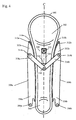
- Figure 4 shows a new chain 300 wrapped around a drive sprocket 304 and driven sprocket 302 on a drive shaft and a driven shaft respectively.
- tensioner arms 308a, 308b On the outside of both the tight strand the slack strand of the chain are tensioner arms 308a, 308b.
- the tensioner arms 308a, 308b each have a shoe 312a, 312b with a chain sliding surface 310a, 310b extending a significant length of the arm.
- the tensioner arms have a pivoting end 330a, 330b for rotation about a fixed pin 306a, 306b and a link end 332a, 332b with a pin 314a, 314b for attaching one or two link pieces 318a, 318b that are free to rotate and are located outside the chain strands between the driving and driven sprockets 302, 304.
- a pivoting tensioner 340 shown in Figures 6-8, which pivots about a shoulder bolt 322 having a housing 320 with a piston 324 biased outwards from the housing 320 by a spring force (not shown) or hydraulic force in addition to spring force, similar to the tensioner shown in US 6,312,351 , which is hereby incorporated by reference.
- the piston's 324 exposed end 324a has a pin 316 that joins the links 318a, 318b together, connecting the opposed tensioner arms 308a, 308b.
- a first angle is formed between the link pieces 318a, 318b of the opposing tensioner arms 308a, 308b and the tensioner arms 308a, 308b may or may not exert a tensioning force of the chain strands.
- a second angle is formed between the links 318a, 318b of the opposing tensioner arms 308a, 308b, less than the first angle when the piston 324 is in the retracted position, drawing the arms 308a, 308b together towards the chain centerline C, tensioning or squeezing the chain strands between the arms 308a, 308b equally and simultaneously.
- the vibrations of one chain strand is linked to the other chain strand and the vibrations are generally neutralized.
- the arms 308a, 308b together to a single tensioning force 340 the force is divided equally between both arms 308a, 308b when the strands are equal. Since the arms 308a, 308b are connected, if one strand of the chain tightens, the other strand must slacken. The total tensioning force is applied to resist the tightening strand.
- pivoting tensioner 340 that pivots about a shoulder bolt 322 would be replaced with a fixed tensioner having a piston with a flat end that contacts the pin that joins the links of the opposing arms; allowing lateral movement of the pin without excessively thrust loading the piston.
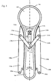
- the chain tensioner system of the present invention also allows for the additional tensioning necessary to tension a worn, elongated chain 301 as shown in Figure 5. Since the arms 308a, 308b are connected and tensioning the chain strand is equal and simultaneous between the two arms 308a, 308b, the increase in chain length is equally absorbed in each chain strand, maintaining the timed relationship of the driving and driven sprockets 302, 304 throughout the life of the chain, eliminating the need to compensate for the change in sequential timing due to chain elongation and enhances the engine performance over its lifetime.
- the piston 324 of the tensioner 340 extends outwards from the housing 320 further, causing the opposing arms 308a, 308b to pull further in towards the chain centerline C and the tensioner 340, squeezing or tensioning the chain's elongated chain strands.
- the chain centerline C is defined as a line spaced equidistant between the two strands of the chain.
Landscapes
- Engineering & Computer Science (AREA)
- General Engineering & Computer Science (AREA)
- Mechanical Engineering (AREA)
- Devices For Conveying Motion By Means Of Endless Flexible Members (AREA)
Applications Claiming Priority (1)
| Application Number | Priority Date | Filing Date | Title |
|---|---|---|---|
| US11/139,837 US20060270502A1 (en) | 2005-05-27 | 2005-05-27 | Tensioner for simultaneously tensioning multiple strands |
Publications (2)
| Publication Number | Publication Date |
|---|---|
| EP1726848A2 true EP1726848A2 (fr) | 2006-11-29 |
| EP1726848A3 EP1726848A3 (fr) | 2007-09-19 |
Family
ID=36808164
Family Applications (1)
| Application Number | Title | Priority Date | Filing Date |
|---|---|---|---|
| EP06005610A Withdrawn EP1726848A3 (fr) | 2005-05-27 | 2006-03-20 | Tendeur pour mettre sous tension simultanément plusieurs lingots |
Country Status (3)
| Country | Link |
|---|---|
| US (1) | US20060270502A1 (fr) |
| EP (1) | EP1726848A3 (fr) |
| JP (1) | JP2006329418A (fr) |
Cited By (4)
| Publication number | Priority date | Publication date | Assignee | Title |
|---|---|---|---|---|
| RU2435088C2 (ru) * | 2009-06-30 | 2011-11-27 | Михаил Иванович Цветков | Способ натяжения зубчатого ремня |
| WO2011130190A3 (fr) * | 2010-04-15 | 2011-12-15 | Borgwarner Inc. | Dispositif de tension à bras oscillant |
| DE102012213925A1 (de) * | 2012-08-07 | 2014-05-22 | Bayerische Motoren Werke Aktiengesellschaft | Fahrzeugantrieb, insbesondere Kettentrieb |
| CN113026629A (zh) * | 2021-03-04 | 2021-06-25 | 广东博智林机器人有限公司 | 清洁设备 |
Families Citing this family (25)
| Publication number | Priority date | Publication date | Assignee | Title |
|---|---|---|---|---|
| DE102004028017A1 (de) * | 2004-06-08 | 2005-12-29 | Bayerische Motoren Werke Ag | Zugmittelanordnung |
| JP4043460B2 (ja) * | 2004-08-19 | 2008-02-06 | 株式会社椿本チエイン | テンショナレバー |
| US7632200B2 (en) * | 2005-06-06 | 2009-12-15 | Borgwarner Inc. | Common link dual arm tensioning device |
| JP2008039097A (ja) * | 2006-08-08 | 2008-02-21 | Honda Motor Co Ltd | チェーンテンショナ装置 |
| US8231489B2 (en) * | 2008-03-19 | 2012-07-31 | Xerox Corporation | One piece belt installation/removal guide |
| US8216100B2 (en) * | 2008-03-19 | 2012-07-10 | Xerox Corporation | Belt installation/removal guide |
| JP5469326B2 (ja) * | 2008-09-29 | 2014-04-16 | ボーグワーナー インコーポレーテッド | テンショニング装置 |
| CN102667243B (zh) * | 2009-11-03 | 2015-04-08 | 博格华纳公司 | 具有移动臂的多段张紧安排 |
| JP4970525B2 (ja) * | 2009-11-04 | 2012-07-11 | 株式会社椿本チエイン | チェーンガイド機構 |
| JP5234670B2 (ja) * | 2010-01-28 | 2013-07-10 | 株式会社椿本チエイン | チェーンガイド機構 |
| JP5355480B2 (ja) * | 2010-04-09 | 2013-11-27 | 株式会社椿本チエイン | チェーンガイド機構 |
| WO2011146570A2 (fr) * | 2010-05-21 | 2011-11-24 | Borgwarner Inc. | Tendeur mécanique à amortissement unidirectionnel |
| EP2574203B1 (fr) * | 2010-05-21 | 2016-06-01 | Borgwarner Inc. | Mécanisme de tension destiné à un système d'entraînement à courroie ou à chaîne continue |
| US20140235386A1 (en) * | 2010-12-16 | 2014-08-21 | Borgwarner Inc. | Tensioning Device |
| JP6331305B2 (ja) * | 2013-09-24 | 2018-05-30 | 三菱自動車工業株式会社 | ベルト張力調整機構 |
| US10408095B2 (en) * | 2015-01-05 | 2019-09-10 | Edward Charles Mendler | Variable compression ratio engine camshaft drive |
| US10487921B2 (en) * | 2016-12-21 | 2019-11-26 | Harley-Davidson Motor Company Group, LLC | Engine with inboard cam drive tensioner |
| JP6906840B2 (ja) * | 2017-04-07 | 2021-07-21 | 株式会社椿本チエイン | チェーンガイド機構 |
| CN109654183A (zh) | 2017-10-12 | 2019-04-19 | 博格华纳公司 | 具有可调节止回阀的液压张紧器 |
| CN109780151B (zh) * | 2019-02-12 | 2023-05-30 | 威海星宜新材料科技有限公司 | 一种链轮传动双向张紧装置 |
| CN111577848A (zh) * | 2020-05-22 | 2020-08-25 | 一汽解放汽车有限公司 | 一种双向张紧器及车辆 |
| US11796040B2 (en) * | 2021-01-22 | 2023-10-24 | Borgwarner Inc. | Method(s) to apply tension to increase drivetrain jump torque capacity |
| US12320425B2 (en) | 2021-01-22 | 2025-06-03 | Borgwarner Inc. | Tooth jump protection device |
| US12435774B2 (en) | 2021-01-22 | 2025-10-07 | Borgwarner, Inc. | Tooth jump protection device |
| US12078245B2 (en) | 2022-05-31 | 2024-09-03 | Borgwarner Inc. | Face of tensioner guide or arm with pattern to influence chain system NVH performance |
Citations (4)
| Publication number | Priority date | Publication date | Assignee | Title |
|---|---|---|---|---|
| US3869138A (en) | 1973-04-04 | 1975-03-04 | Ford Motor Co | Steering device having a chain operated steering gear actuator |
| US5702318A (en) | 1995-03-07 | 1997-12-30 | Tsubakimoto Chain Co. | Chain tensioning device |
| US20030153420A1 (en) | 2002-02-08 | 2003-08-14 | Rogers Clayton R. | Offset starter generator drive utilizing a fixed-offset dual-arm pivoted tensioner |
| WO2005121600A1 (fr) | 2004-06-08 | 2005-12-22 | Bayerische Motoren Werke Aktiengesellschaft | Mecanisme de traction |
Family Cites Families (20)
| Publication number | Priority date | Publication date | Assignee | Title |
|---|---|---|---|---|
| US2129107A (en) * | 1936-03-28 | 1938-09-06 | Fairbanks Morse & Co | Power transmission mechanism |
| US2210276A (en) * | 1938-07-12 | 1940-08-06 | Morse Chain Co | Chain adjuster |
| DE1500474B2 (de) * | 1965-12-02 | 1971-10-07 | Pahtex Project Co GmbH, 4150 Kre feld | Riementrieb mit Spannvorrichtung |
| US3811332A (en) * | 1972-08-22 | 1974-05-21 | Fmc Corp | Automatic tensioning device |
| US3856101A (en) * | 1973-04-04 | 1974-12-24 | Ford Motor Co | Power steering device |
| GB1513722A (en) * | 1974-06-26 | 1978-06-07 | Renold Ltd | Damper apparatus for applying a tensioning force to a member |
| DE3326319A1 (de) * | 1983-07-21 | 1985-01-31 | Dr.Ing.H.C. F. Porsche Ag, 7000 Stuttgart | Kettentrieb einer hubkolben-brennkraftmaschine |
| DE3828350A1 (de) * | 1988-08-20 | 1990-03-01 | Skf Gmbh | Automatische spannvorrichtung |
| US5246404A (en) * | 1989-04-28 | 1993-09-21 | Nhk Spring Company Limited | Unit tensioner |
| DE19536643A1 (de) * | 1995-09-30 | 1997-04-03 | Schaeffler Waelzlager Kg | Spannvorrichtung für einen Steuertrieb |
| US6312351B1 (en) * | 1998-09-21 | 2001-11-06 | Borgwarner Inc. | Hydraulic tensioner with pivotal mount |
| IT1308453B1 (it) * | 1999-04-23 | 2001-12-17 | Iveco Fiat | Dispositivo di trasmissione a catena per il comando delladistribuzione di un motore endotermico a due alberi a camme in testa |
| US6322469B1 (en) * | 2000-04-21 | 2001-11-27 | Borgwarner Inc. | Dual arm chain tensioner for contacting multiple chain strands |
| US6358169B1 (en) * | 2000-05-02 | 2002-03-19 | Borgwarner Inc. | Chain tensioner system having a pivoting tensioner arm |
| US6322470B1 (en) * | 2000-05-17 | 2001-11-27 | Borgwarner Inc. | Pivoting dual arm chain tensioner system for contacting multiple chain strands |
| US6955621B2 (en) * | 2001-04-26 | 2005-10-18 | Borgwarner Inc. | Rotary actuating hydraulic tensioner |
| FR2832358B1 (fr) * | 2001-11-21 | 2004-02-20 | Peugeot Citroen Automobiles Sa | Groupe motopropulseur pour vehicule automobile |
| ITMI20021243A1 (it) * | 2002-06-07 | 2003-12-09 | Regina Ind Spa | Tenditore a fluido per catena |
| US6960145B2 (en) * | 2002-08-30 | 2005-11-01 | Trw, Inc. | Belt tensioner for electric power steering unit |
| DE102005033322A1 (de) * | 2005-07-16 | 2007-01-25 | Schaeffler Kg | Umschlingungstrieb |
-
2005
- 2005-05-27 US US11/139,837 patent/US20060270502A1/en not_active Abandoned
-
2006
- 2006-03-01 JP JP2006054698A patent/JP2006329418A/ja not_active Abandoned
- 2006-03-20 EP EP06005610A patent/EP1726848A3/fr not_active Withdrawn
Patent Citations (4)
| Publication number | Priority date | Publication date | Assignee | Title |
|---|---|---|---|---|
| US3869138A (en) | 1973-04-04 | 1975-03-04 | Ford Motor Co | Steering device having a chain operated steering gear actuator |
| US5702318A (en) | 1995-03-07 | 1997-12-30 | Tsubakimoto Chain Co. | Chain tensioning device |
| US20030153420A1 (en) | 2002-02-08 | 2003-08-14 | Rogers Clayton R. | Offset starter generator drive utilizing a fixed-offset dual-arm pivoted tensioner |
| WO2005121600A1 (fr) | 2004-06-08 | 2005-12-22 | Bayerische Motoren Werke Aktiengesellschaft | Mecanisme de traction |
Cited By (4)
| Publication number | Priority date | Publication date | Assignee | Title |
|---|---|---|---|---|
| RU2435088C2 (ru) * | 2009-06-30 | 2011-11-27 | Михаил Иванович Цветков | Способ натяжения зубчатого ремня |
| WO2011130190A3 (fr) * | 2010-04-15 | 2011-12-15 | Borgwarner Inc. | Dispositif de tension à bras oscillant |
| DE102012213925A1 (de) * | 2012-08-07 | 2014-05-22 | Bayerische Motoren Werke Aktiengesellschaft | Fahrzeugantrieb, insbesondere Kettentrieb |
| CN113026629A (zh) * | 2021-03-04 | 2021-06-25 | 广东博智林机器人有限公司 | 清洁设备 |
Also Published As
| Publication number | Publication date |
|---|---|
| JP2006329418A (ja) | 2006-12-07 |
| EP1726848A3 (fr) | 2007-09-19 |
| US20060270502A1 (en) | 2006-11-30 |
Similar Documents
| Publication | Publication Date | Title |
|---|---|---|
| EP1726848A2 (fr) | Tendeur pour mettre sous tension simultanément plusieurs lingots | |
| EP2496861B1 (fr) | Dispositif de mise en tension à torons multiples avec bras mobiles | |
| EP2574203B1 (fr) | Mécanisme de tension destiné à un système d'entraînement à courroie ou à chaîne continue | |
| US6358169B1 (en) | Chain tensioner system having a pivoting tensioner arm | |
| US6322470B1 (en) | Pivoting dual arm chain tensioner system for contacting multiple chain strands | |
| EP2572120B1 (fr) | Tendeur mécanique à amortissement unidirectionnel | |
| US6849015B2 (en) | Ratcheting pivot arm tensioner with backlash | |
| US7479077B2 (en) | Pivoting mechanical tensioner with compliant blade spring | |
| US20170356529A1 (en) | Variable force tensioning assembly | |
| US7476168B2 (en) | Pivoting mechanical tensioner with cross strand damping | |
| US20130023367A1 (en) | Tensioning arrangement having a swinging arm | |
| EP1915549B1 (fr) | Tendeur mecanique long avec un ressort a lame souple | |
| US8025599B2 (en) | Pivot arm tensioner with sliding ratchet mechanism | |
| EP1043519A2 (fr) | Système à deux tendeurs pour l'entrainement d'un arbre balancier | |
| US7632200B2 (en) | Common link dual arm tensioning device | |
| KR20070044010A (ko) | 복합 체인 구동 가이드 | |
| KR100534702B1 (ko) | V형 엔진의 체인 구동 시스템 |
Legal Events
| Date | Code | Title | Description |
|---|---|---|---|
| PUAI | Public reference made under article 153(3) epc to a published international application that has entered the european phase |
Free format text: ORIGINAL CODE: 0009012 |
|
| AK | Designated contracting states |
Kind code of ref document: A2 Designated state(s): AT BE BG CH CY CZ DE DK EE ES FI FR GB GR HU IE IS IT LI LT LU LV MC NL PL PT RO SE SI SK TR |
|
| AX | Request for extension of the european patent |
Extension state: AL BA HR MK YU |
|
| PUAL | Search report despatched |
Free format text: ORIGINAL CODE: 0009013 |
|
| AK | Designated contracting states |
Kind code of ref document: A3 Designated state(s): AT BE BG CH CY CZ DE DK EE ES FI FR GB GR HU IE IS IT LI LT LU LV MC NL PL PT RO SE SI SK TR |
|
| AX | Request for extension of the european patent |
Extension state: AL BA HR MK YU |
|
| 17P | Request for examination filed |
Effective date: 20080304 |
|
| AKX | Designation fees paid |
Designated state(s): DE FR IT |
|
| STAA | Information on the status of an ep patent application or granted ep patent |
Free format text: STATUS: THE APPLICATION IS DEEMED TO BE WITHDRAWN |
|
| 18D | Application deemed to be withdrawn |
Effective date: 20101001 |