EP1726868B1 - Dispositif de lubrification compact avec une pompe de graissage et un distributeur progressif - Google Patents
Dispositif de lubrification compact avec une pompe de graissage et un distributeur progressif Download PDFInfo
- Publication number
- EP1726868B1 EP1726868B1 EP05011204A EP05011204A EP1726868B1 EP 1726868 B1 EP1726868 B1 EP 1726868B1 EP 05011204 A EP05011204 A EP 05011204A EP 05011204 A EP05011204 A EP 05011204A EP 1726868 B1 EP1726868 B1 EP 1726868B1
- Authority
- EP
- European Patent Office
- Prior art keywords
- lubricant
- lubricating device
- lubricating
- pump
- inner part
- Prior art date
- Legal status (The legal status is an assumption and is not a legal conclusion. Google has not performed a legal analysis and makes no representation as to the accuracy of the status listed.)
- Expired - Lifetime
Links
- 239000000314 lubricant Substances 0.000 title claims abstract description 101
- 230000001050 lubricating effect Effects 0.000 title claims abstract description 50
- 230000000750 progressive effect Effects 0.000 title claims description 23
- 230000033001 locomotion Effects 0.000 claims description 7
- 230000008878 coupling Effects 0.000 claims description 4
- 238000010168 coupling process Methods 0.000 claims description 4
- 238000005859 coupling reaction Methods 0.000 claims description 4
- 230000003287 optical effect Effects 0.000 claims description 3
- 238000007789 sealing Methods 0.000 claims description 3
- 238000011144 upstream manufacturing Methods 0.000 claims description 2
- 238000005461 lubrication Methods 0.000 description 34
- 230000005540 biological transmission Effects 0.000 description 10
- 238000009434 installation Methods 0.000 description 7
- 238000010276 construction Methods 0.000 description 5
- 238000013461 design Methods 0.000 description 5
- 230000004888 barrier function Effects 0.000 description 2
- 238000011161 development Methods 0.000 description 2
- 238000006073 displacement reaction Methods 0.000 description 2
- 238000009826 distribution Methods 0.000 description 2
- 238000004519 manufacturing process Methods 0.000 description 2
- 238000012546 transfer Methods 0.000 description 2
- 230000006835 compression Effects 0.000 description 1
- 238000007906 compression Methods 0.000 description 1
- 239000012530 fluid Substances 0.000 description 1
- 230000004941 influx Effects 0.000 description 1
- 238000003780 insertion Methods 0.000 description 1
- 230000037431 insertion Effects 0.000 description 1
- 238000012544 monitoring process Methods 0.000 description 1
- 230000003716 rejuvenation Effects 0.000 description 1
- 238000003860 storage Methods 0.000 description 1
Images


Classifications
-
- F—MECHANICAL ENGINEERING; LIGHTING; HEATING; WEAPONS; BLASTING
- F16—ENGINEERING ELEMENTS AND UNITS; GENERAL MEASURES FOR PRODUCING AND MAINTAINING EFFECTIVE FUNCTIONING OF MACHINES OR INSTALLATIONS; THERMAL INSULATION IN GENERAL
- F16N—LUBRICATING
- F16N13/00—Lubricating-pumps
- F16N13/22—Lubricating-pumps with distributing equipment
-
- B—PERFORMING OPERATIONS; TRANSPORTING
- B60—VEHICLES IN GENERAL
- B60R—VEHICLES, VEHICLE FITTINGS, OR VEHICLE PARTS, NOT OTHERWISE PROVIDED FOR
- B60R17/00—Arrangements or adaptations of lubricating systems or devices
-
- B—PERFORMING OPERATIONS; TRANSPORTING
- B62—LAND VEHICLES FOR TRAVELLING OTHERWISE THAN ON RAILS
- B62D—MOTOR VEHICLES; TRAILERS
- B62D53/00—Tractor-trailer combinations; Road trains
- B62D53/04—Tractor-trailer combinations; Road trains comprising a vehicle carrying an essential part of the other vehicle's load by having supporting means for the front or rear part of the other vehicle
- B62D53/08—Fifth wheel traction couplings
- B62D53/0885—Comprising devices to limit or to compensate for wear or excessive play; Lubricating, shock absorbing, bearing devices, or the like
-
- F—MECHANICAL ENGINEERING; LIGHTING; HEATING; WEAPONS; BLASTING
- F16—ENGINEERING ELEMENTS AND UNITS; GENERAL MEASURES FOR PRODUCING AND MAINTAINING EFFECTIVE FUNCTIONING OF MACHINES OR INSTALLATIONS; THERMAL INSULATION IN GENERAL
- F16N—LUBRICATING
- F16N25/00—Distributing equipment with or without proportioning devices
Definitions
- the invention relates to a lubricating device for dispensing lubricant from a lubricant source to predetermined lubricant dispensing points comprising a lubricant pump with a displaceably mounted pump element and a progressive distributor with a plurality of parallel mounted metering piston according to the preamble of patent claim 1.
- Such lubrication devices are known from the prior art and are used, for example, for the lubrication of a plurality of lubrication points on a vehicle, such as a truck, on construction machinery or in industrial plants.
- the object of the present invention is based on the known lubricating devices is to provide a lubricating device, which is constructed much more compact, so that attachment even in tight mounting positions is possible.
- individual components to be lubricated a more complex device such as the fifth wheel or trailer hitch of a truck self-sufficient, ie, equipped with its own lubricating already manufacturer, so that these components when installed in the complex device or when installed in the truck not first consuming yet to be connected to a centralized lubrication system.
- the storage of the metering piston and the pump element in the common unit specifically in the inner part designed so that they are mounted parallel to each other, in particular parallel to a preferred axis of the main body.
- the inner part has a substantially cylindrical basic shape, which further favors the compact construction of the entire structural unit.
- groove-shaped channels are formed in the inner part on the outside, which are sealed by inserting the inner part into an outer part sealingly surrounding the inner part.
- this lubricating device can optionally also comprise further components, namely a pump drive and / or a reservoir as lubricant source.
- the pump drive for example, comprise a motor for generating a rotational movement and an eccentric driven by the rotational movement of the motor, which drives the pump element.
- the eccentric comprises a positive guide, so that the pump element is acted upon by the eccentric not only pushing, but also pulling. Return elements, such as springs or the like, which hold the pump element in contact with an eccentric surface, can be avoided. This also favors the simpler and at the same time more compact construction of the entire arrangement.
- At least one return channel for the return of lubricant is provided within the progressive distributor, preferably within the assembly in the outer housing in the case of a blocked lubricant discharge point.
- This return channel may, for example, lead lubricant to the lubricant source, in particular into a serving as a lubricant source reservoir or to another collection point. If a reservoir serving as a lubricant source is connected directly to the unit of lubricant pump and progressive distributor, which will be explained in more detail below, then the return channel of the unit can also transfer recirculated lubricant directly to the reservoir serving as a lubricant source without the need for separate lines.
- At least one return channel as a return for multiple lubricant dispensing points, preferably an optionally branched common return channel for all lubricant dispensing points provided.
- the lubricant discharge points are each provided on the outer part of the assembly and each comprise a bore in which either a lubrication point connection element or a screw plug used fluid-tight, in particular screwed, wherein a common return channel at least a portion of the holes connects with each other and wherein when the lubrication point connection element inserted a bypass sleeve ensures that the return is not blocked with respect to an upstream or downstream bore (lubricant delivery point) and can not occur for output via the lubrication point connection provided lubricant in the return channel.
- This embodiment allows a quasi-automatic connection of the lubricant discharge point to the return channel, in the event that the lubricant discharge point is not needed and sealed with a screw plug.
- a return channel closing the lubricant discharge point would cause the entire progressive distributor is blocked and thus a distribution of lubricant to the other lubrication points is impossible.
- the bypass sleeve may be fixedly arranged in each case at the front end of the lubricating point connecting element, so that it is automatically ensured that no lubricant provided for dispensing via the lubricating point connecting element can enter the return channel.
- the lubricating device may further comprise a reservoir, which is permanently connected to the assembly of progressive distributor and pump element, in particular directly and in particular is rigidly connected thereto.
- the lubricant outlet of the reservoir can be rigidly connected directly to a lubricant inlet of the structural unit.
- the reservoir comprises a follower piston, which acts on the lubricant by means of tension springs with pressure. While the admission of the lubricant in the reservoir by springs is known per se, this is done according to the prior art usually by compression springs which engage on the side facing away from the lubricant of the follower piston.
- the tension springs proposed here are preferably provided in the reservoir within the lubricant-filled chamber, so that an even more compact construction of the entire arrangement can be achieved.
- At least one optical and / or mechanical measuring device can be provided for monitoring the strokes of the pump element and / or the fill level of the reservoir.
- both the strokes of the pump element and the level of the reservoir are first mechanically removed and transmitted via a common transmission rod to an optical measuring tap.
- the common transmission rod can be offset, for example by the eccentric in torsional vibration and be offset independently of approaching the follower piston of the reservoir to its minimum position in a linear deflection.
- the lubricating device according to the invention is also suitable for installation in confined spaces.
- the lubricant pump a lubrication not only at possibly relatively far away from the actual lubrication points places, but also in cramped installation position relatively close to the each to be supplied lubrication points to order.
- Specific applications for the lubrication device according to the invention may be the installation at or near a fifth wheel to supply the lubrication points of a fifth wheel. Also conceivable is the attachment to or near a trailer hitch to supply the lubrication points of a trailer hitch.
- the lubrication device according to the invention can be arranged in the vicinity of the axis of a truck and there smear the lubrication points of these and possibly immediately adjacent axles.
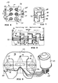
- the lubricating device initially comprises, as the core element, a structural unit 17 in which a lubricant pump 11 and a progressive distributor 13 are housed.
- the structural unit 17 essentially comprises an inner part 28 (cf., Fig. 2, which shows the assembly 17 in a partially open illustration for illustration purposes) and (see Figures 1 and 3) an outer part 27, in which the inner part 28 sealingly received is.
- On the outer part 27 are a plurality of lubricant dispensing points Provided 30 to 35, the funded via the lubricant pump 11 and distributed through the progressive distributor 13 to the lubricant dispensing points lubricant to him - to promote, for example via lines to respectively provided lubrication points.
- the inner part 28 is frictionally held in the outer part 27 and is preferably introduced by sealing in the outer part 27 that the outer part 27 is shrunk.
- a cover 49 terminates the assembly on one end side and is screwed by screws 50 to the outer part 27 of the assembly 17.
- the lubricant pump 11 has a pump element 12 which is mounted displaceably in a bore 51.
- This pump element 12 is driven by a motor 25 and a rotationally connected to the motor eccentric 26, wherein the eccentric 26 comprises a pump element 12 pressingly acting eccentric surface 52 and the eccentric 52 partially surrounding eccentric groove 53.
- the eccentric groove 53 engages a end arranged on the pump element 12 plate 54, so that the pump element 12 is acted upon by the eccentric 26 not only pushing, but also pulling.
- the pump element 12 is thus offset by the eccentric 26 in a reciprocating motion without the provision of other return elements, such as springs o.ä. would be necessary.
- the common assembly 17 of the lubricant pump 11 and progressive distributor 13 is connected directly or rigidly in the present embodiment without the interposition of flexible lines or hoses with a reservoir 43, from which the lubricant pump 11 takes the necessary lubricant to supply the lubrication points.
- the reservoir has a follower piston 45 mounted within the reservoir 43, which is acted upon by tension springs 46, 47, wherein the lubricant in the present embodiment, the tension springs 46, 47 surrounds and is pressurized by this, to the influx of lubricant into the To facilitate the lubricant pump 11.
- the reservoir also has a Filling connection 55, a vent pipe 56 and an overfill 57 on.
- the reservoir 43 can be filled with lubricant via the filling connection 55.
- a measuring transmission rod 58 is provided, which is designed to control the level of the lubricant in the reservoir 43 and / or to scan the number of revolutions of the eccentric 26.
- this transmission or scanning can also be realized in a common measuring transmission rod 58.
- the illustrated measuring transmission rod 58 is slightly linearly deflected by the follower piston 45 shortly before it reaches its end position in the direction of movement of the follower piston 45.
- This linear deflection can be detected via a mechanical and / or electromagnetically operating first scanning element 59, which is designed in particular as a light barrier.
- the deflection of the eccentric 26 is scanned by an eccentric scanning rod 60 formed substantially orthogonally to the measuring transmission rod 58, wherein the distal end of the eccentric sensing rod 60 remote from the measuring transmission rod 58 slides over the eccentric surface 52 during rotation of the eccentric 26, so that the measuring transmission rod 58 is set in torsional vibration.
- the torsional vibration of the Meßübertragungsstange 58 can be detected via a second sensing element 61, which is here also concretely designed as a light barrier, which detects the torsional vibration of the Meßübertragungsstange 58 via a non-rotatably mounted on the Meßübertragungsstange 58 sensing rod 62, ie on the passage of the sensing rod 62 by the Photocell trained second sensing element 61 can detect the number of pump strokes of the pump element 12 of the lubricant pump 11.
- the structural unit 17 is schematically illustrated in a first sectional view through the pump element 12.
- the pump element 12 is slidably mounted in a bore 51 of the inner part 28 as already mentioned.
- the bore 51 communicates with a lubricant inlet 44, via which lubricant can enter the structural unit 17 from a lubricant outlet 48 of the reservoir 43.
- the pump element 12 comprises a delivery piston 63 and a front end projecting beyond the inner part 28, on which the already mentioned plate 54 is arranged, which engages as the head of the pump element in the already mentioned eccentric groove 53.
- the progressive distributor 13 integrated in the assembly 17 comprises a plurality of, in the present embodiment (see Fig. 5) three metering pistons 14 to 16, which are constructed as shown in Fig. 4, namely two outer piston elements 65, 66 and an inner piston member 67th include. Between the central, inner piston element 67 and the outer piston elements 65, 66 a tapered region 68, 69 is provided, which serve for receiving or for transferring lubricant depending on the position of the metering between different channels of the progressive distributor 13.
- the various lines of the progressive distributor 13 are, as can be seen from the perspective view of the inner part 28 in Fig. 7, to a large part of the outer surface (lateral surface) of the inner part 28 forth as groove-shaped channels 18 to 22 formed, in particular milled, which greatly facilitates the production.
- the progression of the metering pistons 14 to 16, that is, the Um Kunststoffschema is clear from the settlement of FIG. 8.
- the volume of lubricant which is present at the front end of a metering piston is dispensed by displacement of the metering piston in the direction of a lubricant delivery point.
- FIGS. 4, 5 and 6 show a preferred embodiment of the lubricant dispensers 30 to 35 on the progressive distributor 13.
- the lubricant dispensing points 30 to 35 initially comprise bores 38, 39, 40, which are provided with an internally threaded portion into which either a closure screw 37 or a lubricating point connecting element 36 can be screwed.
- return passage 29 the plurality of bores 38, 39, 40, if necessary, all holes of the lubricant discharge points 30 to 35 can be connected to each other, is at a non-required lubricant discharge point, which is closed with a screw plug 37, the transferred from the dosing to this lubrication point lubricant transferred into the return channel 29 so that the dosing not blocked by accumulating lubricant, but can continue to advance.
- the lubricant to be dispensed at the respective lubricant dispensing point is therefore conveyed through the central opening 70, 71 of the bypass sleeve 41, 42, whereas Lubricant in the return channel 29 outside of the bypass sleeve within the bore 39 can flow past.
- Fig. 6 the assembly 17 is shown in a frontal view of the lubricant dispensing points 30 to 35, wherein, as shown in Fig. 5, the lubricant dispensing point is closed at the bottom right with a screw plug 37.
- the partially protruding from the assembly 17 pump element 12 can be driven with any pump drive 24, preferably with the interposition of an eccentric 26, wherein an electric, hydraulic, pneumatic or mechanical drive can be considered.
- the unit proposed here is very compact and universally applicable. In each case suitable drive modules can be used.
- a reservoir 43 can be adapted in size and shape as needed and preferably directly connected to form a total compact unit to the assembly 17, possibly also in the form of an interchangeable cartridge. Of course, it is also possible to connect a reservoir via flexible lines with the assembly 17.
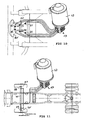
- FIGS. 9 to 11 Typical installation situations for the lubricating device according to the invention are illustrated in FIGS. 9 to 11.
- Fig. 9 the installation of the lubricating device according to the invention comprising a structural unit 17 and a directly connected thereto reservoir 43 for the supply of Lubrication points 72 to 77 of a fifth wheel 78 illustrated.
- the lubricating device according to the invention can either be attached directly to the fifth wheel 78 itself, for example in a frontal area 79 or in the immediate vicinity of the fifth wheel 79 on a vehicle.
- FIG. 10 illustrates an example of application of the lubricating device according to the invention for lubricating a truck trailer coupling 80.
- the truck trailer coupling 80 is supplied with lubricant by the lubrication device according to the invention, here via specifically six lubrication points 81 to 86.
- FIG. 11 another application example for the lubrication of multiple lubrication points 87 to 90 in the region of the axis 91 of a truck is illustrated, wherein the lubricating device according to the invention with the compact unit 17 decentralized, that can be mounted relatively close to the axis 91 of the vehicle.
Landscapes
- Engineering & Computer Science (AREA)
- Mechanical Engineering (AREA)
- General Engineering & Computer Science (AREA)
- Chemical & Material Sciences (AREA)
- Combustion & Propulsion (AREA)
- Transportation (AREA)
- Lubrication Of Internal Combustion Engines (AREA)
- Reciprocating Pumps (AREA)
- General Details Of Gearings (AREA)
- Fertilizing (AREA)
Claims (13)
- Dispositif de lubrification destiné à délivrer un lubrifiant contenu dans une source de lubrifiant en des points de distribution de lubrifiant prédéfinis, comportant une pompe de graissage (11) avec un élément de pompage (12) monté mobile en translation ainsi qu'un distributeur progressif (13) avec une pluralité de pistons de dosage (14, 15, 16) montés parallèles entre eux,
caractérisé en ce que,le distributeur progressif (13) et la pompe de graissage (11) sont agencés dans un bloc comprenant une pièce intérieure (28) et une pièce extérieure (27),et en ce que les pistons de dosage (14, 15, 16) et l'élément de pompage (12) sont logés ensemble dans la pièce intérieure (28). - Dispositif de lubrification selon la revendication 1, caractérisé en ce que les pistons de dosage (14, 15, 16) et l'élément de pompage (12) sont parallèles les uns aux autres, notamment parallèles à un axe préférentiel de la pièce intérieure (28).
- Dispositif de lubrification selon la revendication 1 ou la revendication 2, caractérisé en ce que la pièce intérieure (28) affecte une forme de base sensiblement cylindrique.
- Dispositif de lubrification selon l'une quelconques des revendications 1 à 3, caractérisé en ce que sur l'extérieur de la pièce intérieure (28) sont formés des canaux en forme de rainures (18 à 23) qui sont hermétiquement fermés vis-à-vis de l'extérieur après insertion de la pièce intérieure (28) dans la pièce extérieure (27) qui entoure hermétiquement la pièce intérieure (27).
- Dispositif de lubrification selon l'une quelconque des revendications 1 à 4, caractérisé en ce que le dispositif de lubrification comprend en outre un dispositif d'entraînement de pompe (24), ledit dispositif d'entraînement de pompe (24) comportant un moteur (25) produisant un mouvement rotatif, et un excentrique (26) entraîné par le mouvement rotatif du moteur (25), lequel excentrique (26) entraîne l'élément de pompage (12).
- Dispositif de lubrification selon l'une quelconque des revendications 1 à 5, caractérisé en ce qu'au moins un canal de retour (29) est prévu à l'intérieur du distributeur progressif (13), de préférence à l'intérieur du bloc (17) et notamment dans la pièce extérieure (27), pour permettre le retour du lubrifiant au cas où un point de distribution de lubrifiant (30 à 35) serait bloqué.
- Dispositif de lubrification selon la revendication 6, caractérisé en ce qu'au moins un canal de retour (29) permet le retour de lubrifiant à partir de plusieurs points de distribution de lubrifiant (30 à 35).
- Dispositif de lubrification selon l'une quelconque des revendications 1 à 7, caractérisé en ce que les points de distribution de lubrifiant (30 à 35) sont chacun prévus sur la pièce extérieure du bloc (17) et consistent en un perçage (38 ; 39 ; 40) dans lequel peut être inséré(e) et notamment vissé(e), de manière étanche aux fluides, soit un raccord de point de lubrification (36) soit une vis d'obturation (37),un canal commun de retour (29) reliant entre eux au moins une partie des perçages (38 ; 39 ; 40) et une douille de dérivation (41 ; 42) veillant, lorsqu'un raccord de point de lubrification (36) est en place, à ce que le canal de retour (29) ne soit pas bloqué par rapport à un perçage (38 ; 39 ; 40) situé en amont ou en aval, et également à ce que le lubrifiant devant sortir par le raccord de point de lubrification (36) ne puisse aucunement entrer dans le canal de retour (29).
- Dispositif de lubrification selon l'une quelconque des revendications 1 à 8, caractérisé en ce que le dispositif de lubrification comprend en outre un réservoir (43) qui est relié durablement avec le bloc (17) formé par le distributeur progressif (13) et l'élément de pompage (12).
- Dispositif de lubrification selon la revendication 9, caractérisé en ce qu'une sortie de lubrifiant (48) du réservoir (43) est reliée directement et de manière rigide à l'entrée de lubrifiant (44) du bloc (17) formé par le distributeur progressif (13) et l'élément de pompage (12).
- Dispositif de lubrification selon la revendication 9 ou la revendication 10, caractérisé en ce que le réservoir (43) comprend un piston suiveur (45) qui met en pression le lubrifiant par l'intermédiaire de ressorts de traction (46, 47).
- Dispositif de lubrification selon l'une quelconque des revendications précédentes, caractérisé en ce qu'un dispositif de mesure optique et/ou mécanique est prévu pour contrôler les courses de l'élément de pompage (12) et/ou le niveau de remplissage du réservoir (43).
- Dispositif de lubrification selon l'une quelconque des revendications 1 à 12 destiné à être utilisé pour lubrifier une sellette d'attelage ou pour lubrifier un ou plusieurs essieux adjacents d'un véhicule ou pour lubrifier un dispositif d'attelage de remorque.
Priority Applications (5)
| Application Number | Priority Date | Filing Date | Title |
|---|---|---|---|
| DE502005001430T DE502005001430D1 (de) | 2005-05-24 | 2005-05-24 | Kompakte Schmiereinrichtung mit einer Schmierstoffpumpe und einem Progressivverteiler |
| PL05011204T PL1726868T3 (pl) | 2005-05-24 | 2005-05-24 | Kompaktowe urządzenie smarownicze wyposażone w pompę smarowniczą i w progresywny rozdzielacz |
| EP05011204A EP1726868B1 (fr) | 2005-05-24 | 2005-05-24 | Dispositif de lubrification compact avec une pompe de graissage et un distributeur progressif |
| AT05011204T ATE372483T1 (de) | 2005-05-24 | 2005-05-24 | Kompakte schmiereinrichtung mit einer schmierstoffpumpe und einem progressivverteiler |
| ES05011204T ES2293420T3 (es) | 2005-05-24 | 2005-05-24 | Dispositivo de lubricacion compacto con una bomba de lubricante y un distribuidor progresivo. |
Applications Claiming Priority (1)
| Application Number | Priority Date | Filing Date | Title |
|---|---|---|---|
| EP05011204A EP1726868B1 (fr) | 2005-05-24 | 2005-05-24 | Dispositif de lubrification compact avec une pompe de graissage et un distributeur progressif |
Publications (2)
| Publication Number | Publication Date |
|---|---|
| EP1726868A1 EP1726868A1 (fr) | 2006-11-29 |
| EP1726868B1 true EP1726868B1 (fr) | 2007-09-05 |
Family
ID=34936866
Family Applications (1)
| Application Number | Title | Priority Date | Filing Date |
|---|---|---|---|
| EP05011204A Expired - Lifetime EP1726868B1 (fr) | 2005-05-24 | 2005-05-24 | Dispositif de lubrification compact avec une pompe de graissage et un distributeur progressif |
Country Status (5)
| Country | Link |
|---|---|
| EP (1) | EP1726868B1 (fr) |
| AT (1) | ATE372483T1 (fr) |
| DE (1) | DE502005001430D1 (fr) |
| ES (1) | ES2293420T3 (fr) |
| PL (1) | PL1726868T3 (fr) |
Families Citing this family (2)
| Publication number | Priority date | Publication date | Assignee | Title |
|---|---|---|---|---|
| EP1921326A1 (fr) * | 2006-08-25 | 2008-05-14 | Wärtsilä Schweiz AG | Unité d'alimentation pour liquide sous pression |
| DE102019106531A1 (de) | 2019-03-14 | 2020-09-17 | Baier & Köppel GmbH & Co. KG | Schmierstoffpumpe mit automatisch ankoppelnder Pumpeinheit und Verfahren zum Ankoppeln einer Pumpeinheit an eine Schmierstoffpumpe |
Family Cites Families (3)
| Publication number | Priority date | Publication date | Assignee | Title |
|---|---|---|---|---|
| US4632648A (en) * | 1985-06-24 | 1986-12-30 | Goyne Thomas S | Grease pumps |
| US6244387B1 (en) * | 1999-10-12 | 2001-06-12 | Lincoln Gmbh | Lubricant supply device |
| DE20019186U1 (de) * | 2000-11-10 | 2001-01-11 | Baier & Köppel GmbH & Co, 91257 Pegnitz | Fahrzeuggebundene Zentralschmieranlage |
-
2005
- 2005-05-24 AT AT05011204T patent/ATE372483T1/de active
- 2005-05-24 PL PL05011204T patent/PL1726868T3/pl unknown
- 2005-05-24 EP EP05011204A patent/EP1726868B1/fr not_active Expired - Lifetime
- 2005-05-24 DE DE502005001430T patent/DE502005001430D1/de not_active Expired - Lifetime
- 2005-05-24 ES ES05011204T patent/ES2293420T3/es not_active Expired - Lifetime
Non-Patent Citations (1)
| Title |
|---|
| None * |
Also Published As
| Publication number | Publication date |
|---|---|
| PL1726868T3 (pl) | 2008-01-31 |
| ATE372483T1 (de) | 2007-09-15 |
| EP1726868A1 (fr) | 2006-11-29 |
| ES2293420T3 (es) | 2008-03-16 |
| DE502005001430D1 (de) | 2007-10-18 |
Similar Documents
| Publication | Publication Date | Title |
|---|---|---|
| EP2084451B1 (fr) | Distributeur de lubrifiant | |
| EP2024140B1 (fr) | Pompe à lubrifiant automatique avec piston d'entraînement à double action | |
| EP2053300B1 (fr) | Répartiteur d'ouvertures | |
| DE202008007080U1 (de) | Schmierstoffverteileranlage | |
| EP1631767B1 (fr) | Element distributeur pour des systemes de lubrification | |
| EP1943452B1 (fr) | Agencement de piston, en particulier pour vannes de dosage | |
| EP1726868B1 (fr) | Dispositif de lubrification compact avec une pompe de graissage et un distributeur progressif | |
| DE102020121777A1 (de) | Ventilstößelstange | |
| EP3810463A1 (fr) | Système de nettoyage hydraulique à régulation électronique | |
| DE1528582A1 (de) | Pumpe | |
| EP1798464B1 (fr) | Pompe de graissage | |
| DE102014210909B4 (de) | Schmiermittelpumpe | |
| EP0499347B1 (fr) | Unité centralisée de lubrification | |
| DE10161438B4 (de) | Hubkolbenmaschine | |
| EP2093394A1 (fr) | Dispositif destiné au graissage de cylindres | |
| EP1626225B1 (fr) | Dispositif de distribution de lubrifiant | |
| EP2488782B1 (fr) | Pompe de lubrification et procédé d'alimentation en lubrifiant | |
| EP1538336B1 (fr) | Pompe de dosage | |
| DE10121361A1 (de) | Dosiervorrichtung für Schmiermittel | |
| EP0692668B1 (fr) | Système de graissage par pulvérisation pour un graissage à air au moyen d'huile ou de graisse | |
| DE19818646A1 (de) | Infusionsvorrichtung sowie Verfahren zur Förderung einer Flüssigkeit und Vorrichtung zur Durchführung des Verfahrens | |
| DE3744818C2 (en) | Lubricating system with electromagnetic sensing arrangement | |
| WO2017055103A1 (fr) | Pompe haute pression | |
| DE19837456A1 (de) | Schmiermittelverteiler | |
| DE2122757C3 (de) | Ventil für die saugseitige Durchsatzbegrenzung einer hydraulischen Pumpe |
Legal Events
| Date | Code | Title | Description |
|---|---|---|---|
| PUAI | Public reference made under article 153(3) epc to a published international application that has entered the european phase |
Free format text: ORIGINAL CODE: 0009012 |
|
| 17P | Request for examination filed |
Effective date: 20060707 |
|
| AK | Designated contracting states |
Kind code of ref document: A1 Designated state(s): AT BE BG CH CY CZ DE DK EE ES FI FR GB GR HU IE IS IT LI LT LU MC NL PL PT RO SE SI SK TR |
|
| AX | Request for extension of the european patent |
Extension state: AL BA HR LV MK YU |
|
| GRAP | Despatch of communication of intention to grant a patent |
Free format text: ORIGINAL CODE: EPIDOSNIGR1 |
|
| GRAS | Grant fee paid |
Free format text: ORIGINAL CODE: EPIDOSNIGR3 |
|
| AKX | Designation fees paid |
Designated state(s): AT BE BG CH CY CZ DE DK EE ES FI FR GB GR HU IE IS IT LI LT LU MC NL PL PT RO SE SI SK TR |
|
| GRAA | (expected) grant |
Free format text: ORIGINAL CODE: 0009210 |
|
| AK | Designated contracting states |
Kind code of ref document: B1 Designated state(s): AT BE BG CH CY CZ DE DK EE ES FI FR GB GR HU IE IS IT LI LT LU MC NL PL PT RO SE SI SK TR |
|
| REG | Reference to a national code |
Ref country code: GB Ref legal event code: FG4D Free format text: NOT ENGLISH |
|
| REG | Reference to a national code |
Ref country code: CH Ref legal event code: EP |
|
| REF | Corresponds to: |
Ref document number: 502005001430 Country of ref document: DE Date of ref document: 20071018 Kind code of ref document: P |
|
| REG | Reference to a national code |
Ref country code: IE Ref legal event code: FG4D Free format text: LANGUAGE OF EP DOCUMENT: GERMAN |
|
| REG | Reference to a national code |
Ref country code: SE Ref legal event code: TRGR |
|
| GBT | Gb: translation of ep patent filed (gb section 77(6)(a)/1977) | ||
| PG25 | Lapsed in a contracting state [announced via postgrant information from national office to epo] |
Ref country code: LT Free format text: LAPSE BECAUSE OF FAILURE TO SUBMIT A TRANSLATION OF THE DESCRIPTION OR TO PAY THE FEE WITHIN THE PRESCRIBED TIME-LIMIT Effective date: 20070905 Ref country code: FI Free format text: LAPSE BECAUSE OF FAILURE TO SUBMIT A TRANSLATION OF THE DESCRIPTION OR TO PAY THE FEE WITHIN THE PRESCRIBED TIME-LIMIT Effective date: 20070905 |
|
| REG | Reference to a national code |
Ref country code: PL Ref legal event code: T3 |
|
| REG | Reference to a national code |
Ref country code: ES Ref legal event code: FG2A Ref document number: 2293420 Country of ref document: ES Kind code of ref document: T3 |
|
| REG | Reference to a national code |
Ref country code: IE Ref legal event code: FD4D |
|
| ET | Fr: translation filed | ||
| PG25 | Lapsed in a contracting state [announced via postgrant information from national office to epo] |
Ref country code: GR Free format text: LAPSE BECAUSE OF FAILURE TO SUBMIT A TRANSLATION OF THE DESCRIPTION OR TO PAY THE FEE WITHIN THE PRESCRIBED TIME-LIMIT Effective date: 20071206 |
|
| PG25 | Lapsed in a contracting state [announced via postgrant information from national office to epo] |
Ref country code: CZ Free format text: LAPSE BECAUSE OF FAILURE TO SUBMIT A TRANSLATION OF THE DESCRIPTION OR TO PAY THE FEE WITHIN THE PRESCRIBED TIME-LIMIT Effective date: 20070905 Ref country code: IE Free format text: LAPSE BECAUSE OF FAILURE TO SUBMIT A TRANSLATION OF THE DESCRIPTION OR TO PAY THE FEE WITHIN THE PRESCRIBED TIME-LIMIT Effective date: 20070905 Ref country code: SK Free format text: LAPSE BECAUSE OF FAILURE TO SUBMIT A TRANSLATION OF THE DESCRIPTION OR TO PAY THE FEE WITHIN THE PRESCRIBED TIME-LIMIT Effective date: 20070905 Ref country code: IS Free format text: LAPSE BECAUSE OF FAILURE TO SUBMIT A TRANSLATION OF THE DESCRIPTION OR TO PAY THE FEE WITHIN THE PRESCRIBED TIME-LIMIT Effective date: 20080105 Ref country code: PT Free format text: LAPSE BECAUSE OF FAILURE TO SUBMIT A TRANSLATION OF THE DESCRIPTION OR TO PAY THE FEE WITHIN THE PRESCRIBED TIME-LIMIT Effective date: 20080206 |
|
| PLBI | Opposition filed |
Free format text: ORIGINAL CODE: 0009260 |
|
| PG25 | Lapsed in a contracting state [announced via postgrant information from national office to epo] |
Ref country code: RO Free format text: LAPSE BECAUSE OF FAILURE TO SUBMIT A TRANSLATION OF THE DESCRIPTION OR TO PAY THE FEE WITHIN THE PRESCRIBED TIME-LIMIT Effective date: 20070905 |
|
| PLAX | Notice of opposition and request to file observation + time limit sent |
Free format text: ORIGINAL CODE: EPIDOSNOBS2 |
|
| 26 | Opposition filed |
Opponent name: JOST-WERKE GMBH Effective date: 20080605 |
|
| PG25 | Lapsed in a contracting state [announced via postgrant information from national office to epo] |
Ref country code: DK Free format text: LAPSE BECAUSE OF FAILURE TO SUBMIT A TRANSLATION OF THE DESCRIPTION OR TO PAY THE FEE WITHIN THE PRESCRIBED TIME-LIMIT Effective date: 20070905 |
|
| NLR1 | Nl: opposition has been filed with the epo |
Opponent name: JOST-WERKE GMBH |
|
| PLBB | Reply of patent proprietor to notice(s) of opposition received |
Free format text: ORIGINAL CODE: EPIDOSNOBS3 |
|
| BERE | Be: lapsed |
Owner name: BAIER & KOPPEL G.M.B.H. & CO. Effective date: 20080531 |
|
| PG25 | Lapsed in a contracting state [announced via postgrant information from national office to epo] |
Ref country code: MC Free format text: LAPSE BECAUSE OF NON-PAYMENT OF DUE FEES Effective date: 20080531 |
|
| PG25 | Lapsed in a contracting state [announced via postgrant information from national office to epo] |
Ref country code: BE Free format text: LAPSE BECAUSE OF NON-PAYMENT OF DUE FEES Effective date: 20080531 |
|
| PG25 | Lapsed in a contracting state [announced via postgrant information from national office to epo] |
Ref country code: EE Free format text: LAPSE BECAUSE OF FAILURE TO SUBMIT A TRANSLATION OF THE DESCRIPTION OR TO PAY THE FEE WITHIN THE PRESCRIBED TIME-LIMIT Effective date: 20070905 |
|
| REG | Reference to a national code |
Ref country code: CH Ref legal event code: NV Representative=s name: CAVID GMBH |
|
| PG25 | Lapsed in a contracting state [announced via postgrant information from national office to epo] |
Ref country code: SI Free format text: LAPSE BECAUSE OF FAILURE TO SUBMIT A TRANSLATION OF THE DESCRIPTION OR TO PAY THE FEE WITHIN THE PRESCRIBED TIME-LIMIT Effective date: 20070905 |
|
| PG25 | Lapsed in a contracting state [announced via postgrant information from national office to epo] |
Ref country code: CY Free format text: LAPSE BECAUSE OF FAILURE TO SUBMIT A TRANSLATION OF THE DESCRIPTION OR TO PAY THE FEE WITHIN THE PRESCRIBED TIME-LIMIT Effective date: 20070905 |
|
| PG25 | Lapsed in a contracting state [announced via postgrant information from national office to epo] |
Ref country code: BG Free format text: LAPSE BECAUSE OF FAILURE TO SUBMIT A TRANSLATION OF THE DESCRIPTION OR TO PAY THE FEE WITHIN THE PRESCRIBED TIME-LIMIT Effective date: 20071205 |
|
| PG25 | Lapsed in a contracting state [announced via postgrant information from national office to epo] |
Ref country code: HU Free format text: LAPSE BECAUSE OF FAILURE TO SUBMIT A TRANSLATION OF THE DESCRIPTION OR TO PAY THE FEE WITHIN THE PRESCRIBED TIME-LIMIT Effective date: 20080306 Ref country code: LU Free format text: LAPSE BECAUSE OF NON-PAYMENT OF DUE FEES Effective date: 20080524 |
|
| PG25 | Lapsed in a contracting state [announced via postgrant information from national office to epo] |
Ref country code: TR Free format text: LAPSE BECAUSE OF FAILURE TO SUBMIT A TRANSLATION OF THE DESCRIPTION OR TO PAY THE FEE WITHIN THE PRESCRIBED TIME-LIMIT Effective date: 20070905 |
|
| PLCK | Communication despatched that opposition was rejected |
Free format text: ORIGINAL CODE: EPIDOSNREJ1 |
|
| PLBN | Opposition rejected |
Free format text: ORIGINAL CODE: 0009273 |
|
| STAA | Information on the status of an ep patent application or granted ep patent |
Free format text: STATUS: OPPOSITION REJECTED |
|
| 27O | Opposition rejected |
Effective date: 20101217 |
|
| REG | Reference to a national code |
Ref country code: CH Ref legal event code: NV Representative=s name: REUTELER & CIE S.A. |
|
| PGFP | Annual fee paid to national office [announced via postgrant information from national office to epo] |
Ref country code: SE Payment date: 20110523 Year of fee payment: 7 Ref country code: CH Payment date: 20110527 Year of fee payment: 7 Ref country code: ES Payment date: 20110627 Year of fee payment: 7 Ref country code: FR Payment date: 20110615 Year of fee payment: 7 |
|
| PGFP | Annual fee paid to national office [announced via postgrant information from national office to epo] |
Ref country code: AT Payment date: 20110531 Year of fee payment: 7 Ref country code: PL Payment date: 20110315 Year of fee payment: 7 Ref country code: GB Payment date: 20110527 Year of fee payment: 7 Ref country code: NL Payment date: 20110531 Year of fee payment: 7 |
|
| PGFP | Annual fee paid to national office [announced via postgrant information from national office to epo] |
Ref country code: IT Payment date: 20110528 Year of fee payment: 7 |
|
| REG | Reference to a national code |
Ref country code: NL Ref legal event code: V1 Effective date: 20121201 |
|
| REG | Reference to a national code |
Ref country code: CH Ref legal event code: PL |
|
| REG | Reference to a national code |
Ref country code: SE Ref legal event code: EUG |
|
| REG | Reference to a national code |
Ref country code: AT Ref legal event code: MM01 Ref document number: 372483 Country of ref document: AT Kind code of ref document: T Effective date: 20120524 |
|
| GBPC | Gb: european patent ceased through non-payment of renewal fee |
Effective date: 20120524 |
|
| PG25 | Lapsed in a contracting state [announced via postgrant information from national office to epo] |
Ref country code: LI Free format text: LAPSE BECAUSE OF NON-PAYMENT OF DUE FEES Effective date: 20120531 Ref country code: CH Free format text: LAPSE BECAUSE OF NON-PAYMENT OF DUE FEES Effective date: 20120531 Ref country code: AT Free format text: LAPSE BECAUSE OF NON-PAYMENT OF DUE FEES Effective date: 20120524 |
|
| PG25 | Lapsed in a contracting state [announced via postgrant information from national office to epo] |
Ref country code: IT Free format text: LAPSE BECAUSE OF NON-PAYMENT OF DUE FEES Effective date: 20120524 Ref country code: SE Free format text: LAPSE BECAUSE OF NON-PAYMENT OF DUE FEES Effective date: 20120525 |
|
| REG | Reference to a national code |
Ref country code: FR Ref legal event code: ST Effective date: 20130131 |
|
| PG25 | Lapsed in a contracting state [announced via postgrant information from national office to epo] |
Ref country code: NL Free format text: LAPSE BECAUSE OF NON-PAYMENT OF DUE FEES Effective date: 20121201 |
|
| PG25 | Lapsed in a contracting state [announced via postgrant information from national office to epo] |
Ref country code: GB Free format text: LAPSE BECAUSE OF NON-PAYMENT OF DUE FEES Effective date: 20120524 Ref country code: FR Free format text: LAPSE BECAUSE OF NON-PAYMENT OF DUE FEES Effective date: 20120531 |
|
| REG | Reference to a national code |
Ref country code: ES Ref legal event code: FD2A Effective date: 20130820 |
|
| PG25 | Lapsed in a contracting state [announced via postgrant information from national office to epo] |
Ref country code: PL Free format text: LAPSE BECAUSE OF NON-PAYMENT OF DUE FEES Effective date: 20120524 |
|
| REG | Reference to a national code |
Ref country code: PL Ref legal event code: LAPE |
|
| PG25 | Lapsed in a contracting state [announced via postgrant information from national office to epo] |
Ref country code: ES Free format text: LAPSE BECAUSE OF NON-PAYMENT OF DUE FEES Effective date: 20120525 |
|
| PGFP | Annual fee paid to national office [announced via postgrant information from national office to epo] |
Ref country code: DE Payment date: 20160530 Year of fee payment: 12 |
|
| REG | Reference to a national code |
Ref country code: DE Ref legal event code: R119 Ref document number: 502005001430 Country of ref document: DE |
|
| PG25 | Lapsed in a contracting state [announced via postgrant information from national office to epo] |
Ref country code: DE Free format text: LAPSE BECAUSE OF NON-PAYMENT OF DUE FEES Effective date: 20171201 |