EP1726877A1 - Méthode et appareillage pour contrôler l'injection d'air primaire et d'air secondaire d'un incinérateur de déchets - Google Patents
Méthode et appareillage pour contrôler l'injection d'air primaire et d'air secondaire d'un incinérateur de déchets Download PDFInfo
- Publication number
- EP1726877A1 EP1726877A1 EP06018526A EP06018526A EP1726877A1 EP 1726877 A1 EP1726877 A1 EP 1726877A1 EP 06018526 A EP06018526 A EP 06018526A EP 06018526 A EP06018526 A EP 06018526A EP 1726877 A1 EP1726877 A1 EP 1726877A1
- Authority
- EP
- European Patent Office
- Prior art keywords
- flow
- air
- secondary air
- nozzles
- combustion chamber
- Prior art date
- Legal status (The legal status is an assumption and is not a legal conclusion. Google has not performed a legal analysis and makes no representation as to the accuracy of the status listed.)
- Granted
Links
- 238000000034 method Methods 0.000 title claims abstract description 39
- 239000007924 injection Substances 0.000 title claims description 45
- 238000002347 injection Methods 0.000 title claims description 45
- 238000002485 combustion reaction Methods 0.000 claims abstract description 101
- 239000003546 flue gas Substances 0.000 claims description 58
- 238000006073 displacement reaction Methods 0.000 claims description 51
- 239000007789 gas Substances 0.000 claims description 40
- UGFAIRIUMAVXCW-UHFFFAOYSA-N Carbon monoxide Chemical compound [O+]#[C-] UGFAIRIUMAVXCW-UHFFFAOYSA-N 0.000 claims description 32
- 239000011343 solid material Substances 0.000 claims description 17
- 230000003247 decreasing effect Effects 0.000 claims description 16
- 238000002156 mixing Methods 0.000 claims description 11
- QVGXLLKOCUKJST-UHFFFAOYSA-N atomic oxygen Chemical compound [O] QVGXLLKOCUKJST-UHFFFAOYSA-N 0.000 claims description 10
- 239000001301 oxygen Substances 0.000 claims description 10
- 229910052760 oxygen Inorganic materials 0.000 claims description 10
- FGUUSXIOTUKUDN-IBGZPJMESA-N C1(=CC=CC=C1)N1C2=C(NC([C@H](C1)NC=1OC(=NN=1)C1=CC=CC=C1)=O)C=CC=C2 Chemical compound C1(=CC=CC=C1)N1C2=C(NC([C@H](C1)NC=1OC(=NN=1)C1=CC=CC=C1)=O)C=CC=C2 FGUUSXIOTUKUDN-IBGZPJMESA-N 0.000 claims description 8
- 238000012544 monitoring process Methods 0.000 claims description 7
- 239000012528 membrane Substances 0.000 claims description 5
- 230000008859 change Effects 0.000 claims description 3
- 238000012935 Averaging Methods 0.000 claims description 2
- 239000002699 waste material Substances 0.000 abstract description 22
- 230000001276 controlling effect Effects 0.000 description 9
- 230000010349 pulsation Effects 0.000 description 8
- 239000000203 mixture Substances 0.000 description 6
- 230000009467 reduction Effects 0.000 description 5
- 238000005260 corrosion Methods 0.000 description 4
- 230000007797 corrosion Effects 0.000 description 4
- 238000009434 installation Methods 0.000 description 4
- 230000008569 process Effects 0.000 description 4
- 238000009529 body temperature measurement Methods 0.000 description 3
- 230000000694 effects Effects 0.000 description 3
- 238000010438 heat treatment Methods 0.000 description 3
- 239000000463 material Substances 0.000 description 3
- 230000010355 oscillation Effects 0.000 description 3
- 239000002956 ash Substances 0.000 description 2
- 230000008901 benefit Effects 0.000 description 2
- 238000006243 chemical reaction Methods 0.000 description 2
- 239000010849 combustible waste Substances 0.000 description 2
- 230000001143 conditioned effect Effects 0.000 description 2
- 230000003111 delayed effect Effects 0.000 description 2
- 238000013461 design Methods 0.000 description 2
- 239000000428 dust Substances 0.000 description 2
- 230000005484 gravity Effects 0.000 description 2
- 230000006872 improvement Effects 0.000 description 2
- 238000004056 waste incineration Methods 0.000 description 2
- 239000002028 Biomass Substances 0.000 description 1
- 235000002918 Fraxinus excelsior Nutrition 0.000 description 1
- 230000009471 action Effects 0.000 description 1
- 238000003491 array Methods 0.000 description 1
- 230000002238 attenuated effect Effects 0.000 description 1
- 238000004140 cleaning Methods 0.000 description 1
- 230000001419 dependent effect Effects 0.000 description 1
- 238000001514 detection method Methods 0.000 description 1
- 238000005516 engineering process Methods 0.000 description 1
- 239000003344 environmental pollutant Substances 0.000 description 1
- 238000013213 extrapolation Methods 0.000 description 1
- 239000012634 fragment Substances 0.000 description 1
- 239000000446 fuel Substances 0.000 description 1
- 230000000977 initiatory effect Effects 0.000 description 1
- 238000012423 maintenance Methods 0.000 description 1
- 239000011159 matrix material Substances 0.000 description 1
- 238000012986 modification Methods 0.000 description 1
- 230000004048 modification Effects 0.000 description 1
- 238000007254 oxidation reaction Methods 0.000 description 1
- 230000035515 penetration Effects 0.000 description 1
- 231100000719 pollutant Toxicity 0.000 description 1
- 238000004886 process control Methods 0.000 description 1
- 239000011819 refractory material Substances 0.000 description 1
- 230000001105 regulatory effect Effects 0.000 description 1
- 230000008439 repair process Effects 0.000 description 1
- 239000002910 solid waste Substances 0.000 description 1
- 238000007669 thermal treatment Methods 0.000 description 1
- 230000007704 transition Effects 0.000 description 1
- 239000002912 waste gas Substances 0.000 description 1
Images


Classifications
-
- F—MECHANICAL ENGINEERING; LIGHTING; HEATING; WEAPONS; BLASTING
- F23—COMBUSTION APPARATUS; COMBUSTION PROCESSES
- F23G—CREMATION FURNACES; CONSUMING WASTE PRODUCTS BY COMBUSTION
- F23G5/00—Incineration of waste; Incinerator constructions; Details, accessories or control therefor
- F23G5/08—Incineration of waste; Incinerator constructions; Details, accessories or control therefor having supplementary heating
- F23G5/14—Incineration of waste; Incinerator constructions; Details, accessories or control therefor having supplementary heating including secondary combustion
- F23G5/16—Incineration of waste; Incinerator constructions; Details, accessories or control therefor having supplementary heating including secondary combustion in a separate combustion chamber
-
- F—MECHANICAL ENGINEERING; LIGHTING; HEATING; WEAPONS; BLASTING
- F23—COMBUSTION APPARATUS; COMBUSTION PROCESSES
- F23G—CREMATION FURNACES; CONSUMING WASTE PRODUCTS BY COMBUSTION
- F23G5/00—Incineration of waste; Incinerator constructions; Details, accessories or control therefor
- F23G5/50—Control or safety arrangements
-
- F—MECHANICAL ENGINEERING; LIGHTING; HEATING; WEAPONS; BLASTING
- F23—COMBUSTION APPARATUS; COMBUSTION PROCESSES
- F23L—SUPPLYING AIR OR NON-COMBUSTIBLE LIQUIDS OR GASES TO COMBUSTION APPARATUS IN GENERAL ; VALVES OR DAMPERS SPECIALLY ADAPTED FOR CONTROLLING AIR SUPPLY OR DRAUGHT IN COMBUSTION APPARATUS; INDUCING DRAUGHT IN COMBUSTION APPARATUS; TOPS FOR CHIMNEYS OR VENTILATING SHAFTS; TERMINALS FOR FLUES
- F23L13/00—Construction of valves or dampers for controlling air supply or draught
- F23L13/02—Construction of valves or dampers for controlling air supply or draught pivoted about a single axis but having not other movement
-
- F—MECHANICAL ENGINEERING; LIGHTING; HEATING; WEAPONS; BLASTING
- F23—COMBUSTION APPARATUS; COMBUSTION PROCESSES
- F23L—SUPPLYING AIR OR NON-COMBUSTIBLE LIQUIDS OR GASES TO COMBUSTION APPARATUS IN GENERAL ; VALVES OR DAMPERS SPECIALLY ADAPTED FOR CONTROLLING AIR SUPPLY OR DRAUGHT IN COMBUSTION APPARATUS; INDUCING DRAUGHT IN COMBUSTION APPARATUS; TOPS FOR CHIMNEYS OR VENTILATING SHAFTS; TERMINALS FOR FLUES
- F23L9/00—Passages or apertures for delivering secondary air for completing combustion of fuel
- F23L9/02—Passages or apertures for delivering secondary air for completing combustion of fuel by discharging the air above the fire
-
- F—MECHANICAL ENGINEERING; LIGHTING; HEATING; WEAPONS; BLASTING
- F23—COMBUSTION APPARATUS; COMBUSTION PROCESSES
- F23M—CASINGS, LININGS, WALLS OR DOORS SPECIALLY ADAPTED FOR COMBUSTION CHAMBERS, e.g. FIREBRIDGES; DEVICES FOR DEFLECTING AIR, FLAMES OR COMBUSTION PRODUCTS IN COMBUSTION CHAMBERS; SAFETY ARRANGEMENTS SPECIALLY ADAPTED FOR COMBUSTION APPARATUS; DETAILS OF COMBUSTION CHAMBERS, NOT OTHERWISE PROVIDED FOR
- F23M9/00—Baffles or deflectors for air or combustion products; Flame shields
- F23M9/04—Baffles or deflectors for air or combustion products; Flame shields with air supply passages in the baffle or shield
-
- F—MECHANICAL ENGINEERING; LIGHTING; HEATING; WEAPONS; BLASTING
- F23—COMBUSTION APPARATUS; COMBUSTION PROCESSES
- F23G—CREMATION FURNACES; CONSUMING WASTE PRODUCTS BY COMBUSTION
- F23G2900/00—Special features of, or arrangements for incinerators
- F23G2900/55—Controlling; Monitoring or measuring
- F23G2900/55003—Sensing for exhaust gas properties, e.g. O2 content
-
- F—MECHANICAL ENGINEERING; LIGHTING; HEATING; WEAPONS; BLASTING
- F23—COMBUSTION APPARATUS; COMBUSTION PROCESSES
- F23N—REGULATING OR CONTROLLING COMBUSTION
- F23N2235/00—Valves, nozzles or pumps
- F23N2235/02—Air or combustion gas valves or dampers
- F23N2235/06—Air or combustion gas valves or dampers at the air intake
-
- F—MECHANICAL ENGINEERING; LIGHTING; HEATING; WEAPONS; BLASTING
- F23—COMBUSTION APPARATUS; COMBUSTION PROCESSES
- F23N—REGULATING OR CONTROLLING COMBUSTION
- F23N3/00—Regulating air supply or draught
- F23N3/04—Regulating air supply or draught by operation of single valves or dampers by temperature sensitive elements
-
- F—MECHANICAL ENGINEERING; LIGHTING; HEATING; WEAPONS; BLASTING
- F23—COMBUSTION APPARATUS; COMBUSTION PROCESSES
- F23N—REGULATING OR CONTROLLING COMBUSTION
- F23N5/00—Systems for controlling combustion
- F23N5/02—Systems for controlling combustion using devices responsive to thermal changes or to thermal expansion of a medium
Definitions
- the invention relates to a device for incinerating waste comprising rows of secondary air nozzles divided into segments.
- the invention relates to a method for controlling several parameters of secondary air injection including at least one of the parameters: flow, speed, turbulence, volume, composition and temperature, for optimizing the incinerating process in an incineration system.
- the invention relates to a method for controlling primary air injection.
- the invention also relates to an incineration equipment, functioning in accordance with said methods enabling the control of primary and secondary air injection.
- the combustion process of waste is a rather complex one because homogeneous and heterogeneous reactions take place, not only on the incineration grate, but also above the grate.
- the furnace-boiler part comprising a combustion chamber and a post-combustion chamber is a critical part of an incineration installation and needs to be designed with great care.
- the most important properties for this type of furnace-boiler are good performance, high flexibility, good availability and reliability with an acceptable lifetime of the different pressure parts. Flexibility is of utmost importance, due to the variability of the waste characterized by e.g. its composition and calorific value.
- the furnace-boiler must be able to perform under these permanent changing conditions and produce steam or heat, in an as stable as possible way.
- the terms displacement body, bluff body and prism body are used interchangeably.
- one of the main problems of obtaining an efficient combustion is the good mixing of the secondary air.
- the introduction of secondary air is difficult to fine-tune.
- adequate mixing of the secondary air with the combustible waste gases is not achieved, resulting in an incomplete combustion.
- the introduced secondary air is often not properly conditioned to take immediately part in the post-combustion process when injected in the furnace-boiler. Consequently, it will take a longer time for the post-combustion process to reach a complete burnout of the flue gases, and injection of non-conditioned secondary air in the furnace-boiler may even slow down the post-combustion process.
- Another problem is that the temperature throughout a cross-section of the post-combustion chamber is not constant; pockets of flue gases are sometimes hotter or cooler than the optimum temperature causing undesirable side effects such as corrosion, slagging and fouling.
- the present invention provides a new device comprising an improvement on the primary air and secondary air injection systems, a method for controlling several parameters of the secondary air, including flow, speed, turbulence, volume, composition and temperature, and a method for controlling primary air injection.
- a new device comprising an improvement on the primary air and secondary air injection systems, a method for controlling several parameters of the secondary air, including flow, speed, turbulence, volume, composition and temperature, and a method for controlling primary air injection.
- Another embodiment of the present invention is a device as described above wherein each segment and segment opposite thereto form pairs of segments on opposite pairs of rows of secondary air nozzles.
- Another embodiment of the present invention is a device as described above wherein the air flow to each segment is controlled by one or more valves and/or by modulating one or more air fans and/or according to the selected diameters of the secondary air injection nozzles within said segment.
- Another embodiment of the present invention is a device as described above further comprising any array of four or more temperature sensors, each sensor located above an area defined by a pair of segments.
- Another embodiment of the present invention is a device as described above whereby the secondary air is provided via secondary air supply ducts ending in injection nozzles, passing through the front- and rear- wall of said device as well as through the membrane-wall of the displacement body.
- Another embodiment of the present invention is a device as described above whereby, the secondary air supply duct consists of two or more concentric ducts, inside of the displacement body or along the exterior of the furnace-boiler walls.
- Another embodiment of the present invention is a device as described above whereby the inner front and rear walls of said device are bent in such shape that, together with the outline of the displacement body, two venturi-shaped flue gas passages with an opening angle ( ⁇ / ⁇ ) between 20° and 40° are created in order to increase the flue gas turbulence in the venturi-shaped mixing zone.
- Another embodiment of the present invention is a device as described above wherein the displacement body is made in the shape of a distorted rhomboidal prism.
- Another embodiment of the present invention is a method for incinerating solid materials comprising the use of a device as described above.
- Another aspect of the invention relates to a method for the thermal treatment of solid materials in an incinerator comprising a combustion chamber and a post-combustion chamber, said method essentially consisting of:
- Present invention provides a method for controlling several parameters of the primary air and secondary air injection and a device able to perform said method, which will greatly improve the efficiency of the combustion process, which will reduce emissions and will comply with the more severe combustion requirements.
- One aspect of present invention relates to a combustion device and method, characterized by a specific secondary air injection system in the center of the combustion zone, immediately at the combustion chamber exit and before entering the post-combustion chamber, and controlled by at least one of the following parameters: flow, turbulence, volume, composition, speed, or temperature.
- the secondary air is supplied into the divided flue gas streams "A" and "B” (see Figure 1 a), via a secondary air supply duct [12], [13], [14] to several nozzle inlets [30] and [31] in the furnace-boiler front [6] and rear [7] wall and on both sides of the displacement body [5].
- the objective of the present invention is to optimize the combustion process in an incineration system and to assure a complete combustion of the flue gases, in order to fulfill the requirements of the EU-directive (2000/076) and increase performance and lifetime of pressure part components of the incineration device.
- the use of this new, controlled secondary air injection system leads to more effective mixing between the oxygen supplied by the secondary air and the flue gases and will increase combustion performance. Consequently, said device and method results in a much shorter and clearly defined burn-out-zone of the flue gases in the post-combustion chamber of the furnace-boiler, a few meters above the displacement body.
- the listed parameters can be adjusted according to the requirements of the incinerating process.
- a suitable furnace-boiler geometry can contribute to a more uniform velocity and gas flow distribution and avoid flue gas recirculation or dead zones throughout the different sections of the furnace-boiler. Therefore, the furnace-boiler has a double venturi-like transition section between combustion and post-combustion chamber, which also promotes the mixing of the partial flue gas flows "A" and "B" with the injected secondary air. Improved mixing of the secondary air and the flue gases increases the efficiency of the combustion process.
- the method is characterized by the fact that the flow of the secondary air is continuously interrupted, in order to generate an additional pulsation with the secondary airflow when released in the furnace-boiler through the secondary air injection nozzles.
- the flow of the secondary air is continuously interrupted either in the secondary air supply ducting [12], [13], [14], or in the nozzle [30], [31] or in both (see Figures 1b, 2a, 2b, 2c, 2d, 3a, 3 b, 3c).
- the device and method are characterized by the fact that the secondary airflow is supplied via nozzles having different cross-sectional diameters and/or by secondary air ducting, permitting different controlled secondary airflow to several zones, spread over the total width of the post-combustion chamber.
- the diameters of the nozzles conducting the secondary air in the furnace-boiler are alternately of different size ( Figure 5). This results in the injection of alternately different secondary airflow in the post-combustion chamber, initiating additional turbulence in the furnace-boiler.
- the secondary air is supplied via a combined secondary air supply ducting [12], [13], [14] composed of two or more concentric tubes [47], [48], [49] ( Figure 6).
- the supply of secondary air via said concentric ducts permits a more accurate control of secondary air to individual zones over the width of the post-combustion chamber.
- Using concentric tubes fitting in each other allows the supply of different flows of secondary air via only one single supply ducting. Different flows of the secondary air may be required depending on the stage of the combustion process in a specific zone.
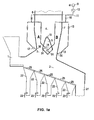
- FIG. 1a Another aspect of the present invention relates to a device for waste incineration ( Figure 1a), characterized by the fact that said device supplies secondary air via a secondary air duct [12], [13], [14] ending in several nozzles [30], [31] located immediately at the combustion chamber exit [3] and before entering into the post-combustion chamber [4], with control of the secondary air by at least one of the following parameters: flow, turbulence, volume, composition, speed, or temperature.
- the device provides secondary air via secondary air ducting [12], [13], [14] to nozzles [30], [31], passing through the front [6] and rear [7] wall of the furnace-boiler and through the front and rear wall of the displacement body (Figure 1a).
- An important advantage of this design of secondary air injection is the improvement of the flue gas mixing, thanks to the reduction of the necessary penetration depth of the secondary air jet to nearly 1 ⁇ 4 of the original furnace-boiler depth. Secondary air injection via a large number of smaller nozzles with lower individual airflow allows a much quicker heating of the secondary air to the required reaction temperature for CO-oxidation (ca. 600°C).
- the invention relates to said device whereby the secondary air supply ducting is composed of at least two or more concentrical circular ducts. This allows supply of different flows of secondary air via only one single supply ducting. Two or more concentric ducts allow for independently controlled flows of secondary air to individual zones over the width of the post-combustion chamber, e.g. corresponding to the different grate lanes ( Figure 6).
- the invention relates to said device where unstable flaps [20] are situated inside the secondary air supply duct or injection nozzles or both, able to create a pulsation of the secondary air when injected in the combustion chamber of the incineration device (Figure 1b).
- the frequency of the oscillation can be adjusted by a movable weight on the flaps, changing the position of the gravity center.
- the invention in another embodiment, relates to said device with pairs of separate secondary air supply ducts ending with nozzles of alternately different diameter.
- the arrangement is such that the secondary air supply duct with nozzles [12] ( Figure 1a) located at the furnace-boiler front wall [6] and the secondary air supply duct with nozzles situated in the front wall of the displacement body [14] form one pair.
- the secondary air supply duct [13] with nozzles located at the furnace-boiler rear wall [7] and the secondary air supply duct with nozzles situated in the rear wall of the displacement body [14] form another pair.
- the device is characterized by the fact that two opposite nozzles have a different outlet diameter (Figure 5). This means that two opposite, but in-line nozzles have respectively a large [43] and a small [42] inside diameter.
- the invention-related device includes a displacement body [5] with a profile of a distorted rhombus as in Figures 4 and 6.
- FIG. 1a An example of a device and method of how several parameters for secondary air injection are controlled according to the invention is illustrated in Figure 1a.
- the system supplies secondary air in the passages "A” and “B” by means of nozzles [30], [31] as shown in Figure 1 b.
- the secondary air is optimally injected directly into the flow of waste gases, at the combustion chamber exit and at the entrance of the post-combustion chamber.
- the secondary air is injected into the divided flue gas streams "A” and "B”, via a secondary air supply duct [12], [13], [14] leading to several nozzles [30], [31] located in the furnace-boiler front and rear wall and on both sides of the displacement body [5].
- furnace-boiler front [6] and rear [7] membrane wall and the membrane wall [19] of the displacement body [5] are provided with refractory materials through which a series of nozzles [30], [31] pass.
- the total oxygen introduced into furnace-boiler as disclosed herein as primary and secondary air is determined by the oxygen content of the flue gases.
- the oxygen so introduced is distributed between the primary and secondary inlet systems according to methods of the art.
- the distribution primary and secondary air is attenuated by monitoring the temperatures in gas flow sections A and B as described below.
- a flue gas temperature measurement is installed into a furnace-boiler as described herein, a few meters above the outlet of the two flue gas streams "A" and “B,” to measure the actual temperature for each flow section.
- the purpose of this temperature measurement is to maintain, during the combustion process, nearly the same flue gas temperature (ca. 1.000°C) in front section "A” as in the rear section "B", by means of a variable secondary air flow. Consequently, when a flue gas temperature increase is observed in section "A", the secondary airflow for section "A" is increased until the equal temperature profile is automatically re-established. At the same time, secondary airflow for section “B” is reduced in order to keep the total secondary airflow constant, unless a general temperature increase is noticed in both sections whereby the total secondary airflow is increased.
- the temperature measurement is linked to the capability of the secondary air injection system to respond to modified furnace conditions such as a shift in the heat-release profile on the grate. For instance, when high calorific waste suddenly enters the furnace, combustion of the waste will start on the first element of the grate and the flue gas temperature in section A will rise above the temperature setpoint, so shifting the heat release profile towards the feeding hopper.
- the setpoint may be any temperature defined by the user.
- the set point temperature may be a value in the range of 900 to 1100 °C, 950 to 1050 °C, 920 to 1020 °C, 970 to 1070 °C, 980 to 1080 °C, 970 to 1030 °C, 980 to 1020 °C or 990 to 1010 °C,
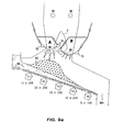
- the system recognizes the over-temperature and the temperature imbalance and reacts accordingly as described above. A similar process, but in the opposite direction will occur when low calorific waste is introduced and combustion on the grate is delayed. This is exemplified in Figure 9a, wherein a temperature sensor [91], [92] is placed in each of the flue gas streams above the displacement body [5].
- the detection of the temperature in the gas flow sections A and B is used as a pre-indication of the type of waste entering the furnace, and may be connected to the process control of the grate speed and primary air distribution along the different grate elements.
- the process control of the grate speed and primary air distribution along the different grate elements For instance, as in Figure 9a, when high calorific waste [93] enters a furnace as disclosed herein, combustion of the waste will start on the first element of the grate and the heat release profile of the grate will be shifted towards the waste input (hopper) end [99] of the grate. The consequence is that waste will be incinerated towards the waste input end of the grate [99].
- the shift of heat release profile is detected by the flue gas temperature sensor in section A [91], which would rise above the temperature setpoint.
- the setpoint may be any temperature defined as described above.
- the system detects the over-temperature and recognizes the temperature imbalance between section A and section B, and reacts by decreasing the supply of primary air beneath or proximal to the high calorific waste [R1 to R2] so as to shift the heat-release profile back towards to the region of the post-combustion chamber.
- the primary airflow in the remaining positions of the grate [R3 to R5] is increased in order to keep the total primary airflow constant.
- a similar process, but in the opposite direction will occur when low calorific waste is introduced, and combustion on the grate is delayed, so shifting the heat release profile in the direction of the waste output [901] ( Figure 9b).
- each row of secondary air nozzles is divided into two or more segments, each segment comprising two or more nozzles, such that the flow of air through any one segment can be the same or different from that of directly adjacent segments.
- An air flow in one segment may be controlled by one or more valves, by modulating one or more air fans, by controlling the nozzle diameters within a certain range, or a combination of these.
- the diameters of the nozzles belonging to a segment are the same or are alternately of different sizes such as that shown in Figure 5. It is within the scope of the invention that the diameters of the nozzles belonging to a segment are placed opposite to nozzles of the same diameter on the corresponding opposing wall. It is further within the scope of the invention that the diameters of the nozzles belonging to a segment are placed opposite to nozzles of a different diameter on the corresponding opposing wall. When placed opposite nozzles of a different diameter, it is within the scope of the invention that the nozzles of small diameter nozzles are placed opposite to nozzles having a larger diameters.
- Figure 7 shows one pair of rows of secondary nozzles [71], [72] divided into three separate segments [73], [74], [75] Control of secondary air thereto is achieved by means of a valve [77] controlling the air flow to each segment, and a valve [78] controlling the air flow to each row of nozzles.
- an array of temperature sensors is installed a few meters above the outlet of the two gas flow sections "A" and “B” to measure the actual temperature for each flow section.
- the number of temperature sensors installed is equal to the number of segments that each pair of rows of nozzles is divided into.
- FIG. 8 shows an example of a furnace-boiler according to the present invention having an array of temperature sensors [81] placed above the displacement body [5].
- the segment injection areas as described above are labeled [A1], [A2] and [A3], defined by the nozzle segments [73], [74], [75].
- Temperature sensors [SA1], [SA2] and [SA3] are placed above and in the vicinity of the respective segment injection areas [A1], [A2] and [A3].
- a similar arrangement of temperature sensors [SB1], [SB2] and [SB3] is placed above and in the vicinity of the segment injection areas of the other passage ("B"), said segment injection areas labeled by [B1], [B2] and [B3].
- the "vicinity" of the segment injection areas may be determined by extrapolating the positions and sizes of the segment injection areas at the narrowed entrance of the post-combustion chamber to the cross-section of the post-combustion chamber. This extrapolation is performed using methods of the art.
- a precise control of the temperature of the air in the post-combustion chamber is important for minimizing the effects of corrosion, slagging and fouling.
- the inventors have found that differences in temperature exists within each section of the post-combustion chamber, e.g. the temperature across section A might be found to be hotter in the middle compared with the edges.
- the inventors have found that the differences can be partially or completely modulated by changing the rate of injection (flow) of secondary air in the region below the local temperature difference, so leading to a reduction in corrosion, slagging and fouling in the post-combustion chamber and in the boiler.
- each pair of rows of nozzles is divided into one or more segments as described above, and each temperature sensor of the array is placed above and in the vicinity of each segment injection area; in this arrangement, the temperature detected by each sensor determines the rate at which air is injected by the corresponding segments of nozzles.
- the air flow from nozzles [74] in an indicated segment injection area [A2] is determined by the reading of sensor [SA2]; the air flow from nozzles [73] in an indicated segment injection area [A1] is determined by the reading of sensor [SA1]; the air flow from nozzles [75] in an indicated segment injection area [A3] is determined by the reading of sensor [SA3].
- the furnace comprises a two dimensional matrix of primary air input zones, along the grate and across the width of the grate.
- the temperature change detected by the array of temperature sensors in the post-combustion chamber influences the primary air flow across the width of the grate.
- a temperature sensor that indicates an increase in temperature causes a reduction in flow in one or more the primary air input zones located below the position of said sensor. For example, should sensor [SA1] detect an increase in temperature, the corresponding primary air entrance zone located below [SA1] would respond by reducing the flow of air [R1L] and/or [R2L] and/or [R3L]. The air flow in the remaining primary air entrance zones is increased so as to maintain the correct total air supply.
- the device and method as disclosed herein also reduces the corrosion potential, by minimizing the CO-concentration (reducing atmosphere) in the flue gas flow in presence of HCl, Cl and Cl-combination.
- the refractory lining extent in the first pass can be reduced to the strict minimum, just enough to comply with the two seconds/850°C rule. Furthermore, as the burnout is fully completed a few meters above the displacement body, there is no further need to protect the membrane walls of the post-combustion chamber and first pass above this level.
- the supply of secondary air is continuously disturbed with the purpose of creating a pulsation of the secondary air before entering the furnace-boiler.
- this pulsation can be produced by means of unstable flap [20], placed in the secondary air supply ducts [12], [13], [14] as shown in Figure 1b.
- a main secondary air duct [16] feeds said secondary air supply ducts [12], [13], [14].
- the permanent movement of the flap 20 will create a pulsating secondary air flow in the area of both restrictions of section "A" and "B".
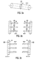
- Figures 2a, 2b, 2c and 2d explain in detail the action of the constant moving flap 20 in a hinged configuration.
- Figure 2a shows a self-moving oscillating flap [20] without external drive.
- the oscillation amplitude of these self-moving flaps is depending upon the length, the shape and the weight of the flaps.
- an oscillating impulse strength can be realized in a single nozzle as explained in Figure 3a, with an external driven (such as an electric motor M) rotating circular valve [20].
- Externally driven valves [20] can be located within the individual nozzles [30], [31], as shown in Figure 3b, or within the common secondary air supply ducts [12], [13], [14] as shown in Figure 3c.
- valves [20] respectively in the secondary air supply ducts [12], [13], [14] as shown on Figure 3c, or in each individual nozzle [30], [31], as shown in Figure 3b, has a different influence on the oscillation impulse of the nozzles.
- the means to pulsate air as described above may be installed in any furnace-boiler according to the present invention.
- Figure 1a shows the cross section of the furnace-boiler, combustion and post-combustion chamber of a typical incinerator arrangement, particularly designed for incineration of solid waste or biomass, consisting of a furnace [2] with an incineration grate [25], receiving the solid materials through a feeding hopper with pusher [1].
- the produced flue gases are conducted in a combustion chamber [3] and a post-combustion chamber [4].
- Hoppers [22] underneath the grate [25] are placed for collection of the siftings of the grate and serving at the same time as primary air supply channels.
- the primary air is supplied via several air ducts [23].
- the ashes fall via a shaft [21] into an ash extractor (not shown).
- the produced flue gases, not yet completely burned out, are divided in two streams by a displacement body [5], installed at the entrance of the post-combustion chamber [4].
- the displacement body [5] By placing the displacement body [5] at the combustion chamber exit [3] and the entrance into the post-combustion chamber [4], the flue gases passage is divided in two flow channels "A" and "B". Secondary air is injected through four rows of nozzles located at the entrance of the post-combustion chamber [4] where the displacement body [5] is located.
- the secondary air is conducted via nozzles [30] in the front [6] and rear wall [7] of the furnace-boiler as well as via nozzles [31] of the displacement body [5].
- the flue gases are mixed with secondary air, resulting in an almost complete burnout of the flue gases a few meters above the displacement body [5] and also resulting in shorter flames and more uniform oxygen concentrations.
- the secondary air is supplied by a secondary air fan [9] via secondary air ducts [11], provided with secondary air regulating valves [15], to the secondary air supply ducts [12], [13], [14] into the injection nozzles [30], [31].
- Figures 5, 6, 7, 8 , 11 and 12 disclose two secondary air supply ducts, aligned in parallel, and nozzles [42], [43] with alternate different diameter. Two opposite nozzles have respectively a large [43] and a small diameter [42] in order to improve the mixing of the injected secondary air with the flue gases.
- Figure 6 illustrates the use of different concentric ducts [47], [48], [49], to supply secondary air to duct [14]. Due to the fact that three concentric tubes [47], [48], [49] are provided, three different flows of secondary air can be independently controlled and injected over the total width of the furnace-boiler.
Landscapes
- Engineering & Computer Science (AREA)
- Mechanical Engineering (AREA)
- General Engineering & Computer Science (AREA)
- Chemical & Material Sciences (AREA)
- Combustion & Propulsion (AREA)
- Incineration Of Waste (AREA)
- Exhaust Gas After Treatment (AREA)
Priority Applications (1)
| Application Number | Priority Date | Filing Date | Title |
|---|---|---|---|
| EP06018526A EP1726877B1 (fr) | 2002-04-03 | 2003-04-03 | Méthode et appareillage pour contrôler l'injection d'air primaire et d'air secondaire d'un incinérateur de déchets |
Applications Claiming Priority (4)
| Application Number | Priority Date | Filing Date | Title |
|---|---|---|---|
| EP02447055 | 2002-04-03 | ||
| US37199202P | 2002-04-11 | 2002-04-11 | |
| EP03717267A EP1490632B1 (fr) | 2002-04-03 | 2003-04-03 | Procede et dispositif servant a commander l'injection d'air primaire et secondaire dans un systeme d'incineration |
| EP06018526A EP1726877B1 (fr) | 2002-04-03 | 2003-04-03 | Méthode et appareillage pour contrôler l'injection d'air primaire et d'air secondaire d'un incinérateur de déchets |
Related Parent Applications (1)
| Application Number | Title | Priority Date | Filing Date |
|---|---|---|---|
| EP03717267A Division EP1490632B1 (fr) | 2002-04-03 | 2003-04-03 | Procede et dispositif servant a commander l'injection d'air primaire et secondaire dans un systeme d'incineration |
Publications (2)
| Publication Number | Publication Date |
|---|---|
| EP1726877A1 true EP1726877A1 (fr) | 2006-11-29 |
| EP1726877B1 EP1726877B1 (fr) | 2008-08-13 |
Family
ID=28676409
Family Applications (2)
| Application Number | Title | Priority Date | Filing Date |
|---|---|---|---|
| EP03717267A Expired - Lifetime EP1490632B1 (fr) | 2002-04-03 | 2003-04-03 | Procede et dispositif servant a commander l'injection d'air primaire et secondaire dans un systeme d'incineration |
| EP06018526A Expired - Lifetime EP1726877B1 (fr) | 2002-04-03 | 2003-04-03 | Méthode et appareillage pour contrôler l'injection d'air primaire et d'air secondaire d'un incinérateur de déchets |
Family Applications Before (1)
| Application Number | Title | Priority Date | Filing Date |
|---|---|---|---|
| EP03717267A Expired - Lifetime EP1490632B1 (fr) | 2002-04-03 | 2003-04-03 | Procede et dispositif servant a commander l'injection d'air primaire et secondaire dans un systeme d'incineration |
Country Status (7)
| Country | Link |
|---|---|
| EP (2) | EP1490632B1 (fr) |
| CN (1) | CN100402925C (fr) |
| AT (2) | ATE343766T1 (fr) |
| AU (1) | AU2003221547A1 (fr) |
| DE (2) | DE60322986D1 (fr) |
| ES (1) | ES2275086T3 (fr) |
| WO (1) | WO2003083370A1 (fr) |
Cited By (2)
| Publication number | Priority date | Publication date | Assignee | Title |
|---|---|---|---|---|
| WO2015040272A1 (fr) * | 2013-09-18 | 2015-03-26 | Outotec (Finland) Oy | Procédé et dispositif de traitement des gaz de procédé s'écoulant d'un four de pyrométallurgie dans une chaudière de récupération |
| FR3104683A1 (fr) * | 2019-12-13 | 2021-06-18 | Cnim Groupe | Procédé de régulation d’une installation de combustion, ainsi qu’installation de combustion correspondante |
Families Citing this family (10)
| Publication number | Priority date | Publication date | Assignee | Title |
|---|---|---|---|---|
| DE102005009957B4 (de) * | 2005-03-04 | 2007-02-01 | Martin GmbH für Umwelt- und Energietechnik | Verfahren zum Verbrennen von Brennstoffen, insbesondere Abfall |
| DE102006031900A1 (de) * | 2006-07-07 | 2008-01-10 | Rwe Power Ag | Verfahren zur Regelung der Verbrennungsluftzufuhr an einem mit fossilen Brennstoffen befeuerten Dampferzeuger |
| DE102011002205A1 (de) * | 2011-04-20 | 2012-10-25 | Alstom Technology Ltd. | Abhitze-Dampferzeuger sowie ein Verfahren zum Betreiben eines Abhitze-Dampferzeugers |
| CN103032885B (zh) * | 2012-12-20 | 2016-08-03 | 北京中煤神州节能环保技术开发有限公司 | 波形分离旋转飞灰燃烬装置 |
| CN103939917B (zh) * | 2014-04-03 | 2016-03-23 | 山东威澳环保科技有限公司 | 一种炉内强化燃烧装置 |
| DE102015117718A1 (de) * | 2015-10-19 | 2017-04-20 | Karlsruher Institut für Technologie | Feuerungssystem und Verfahren zu dessen Betrieb |
| CN105536372B (zh) * | 2016-01-08 | 2017-07-11 | 江苏新中环保股份有限公司 | 烟气自动均衡分配装置 |
| DE102017008123A1 (de) * | 2017-08-30 | 2019-02-28 | Martin GmbH für Umwelt- und Energietechnik | Feuerungsanlage und Verfahren zum Betreiben einer Feuerungsanlage |
| JP7131900B2 (ja) * | 2017-11-14 | 2022-09-06 | クボタ環境エンジニアリング株式会社 | 焼却炉及び焼却炉の排ガス処理方法 |
| EP3896337A1 (fr) | 2020-04-16 | 2021-10-20 | General Electric Company | Système de combustion pour une chaudière dotée d'un moyen de distribution de flux de carburant dans un brûleur et procédé de combustion |
Citations (11)
| Publication number | Priority date | Publication date | Assignee | Title |
|---|---|---|---|---|
| DE3038875A1 (de) * | 1980-10-15 | 1982-06-03 | Vereinigte Kesselwerke AG, 4000 Düsseldorf | Muellverbrennungsanlage |
| EP0312818A2 (fr) * | 1987-10-23 | 1989-04-26 | Küpat AG | Procédé et dispositif d'incinération d'un combustible inhomogène |
| CA1324537C (fr) * | 1988-04-15 | 1993-11-23 | Brian Robin Blackwell | Methode et appareil pour ameliorer le melange de fluides et gaz dans une chaudiere |
| EP0576955A2 (fr) * | 1992-06-19 | 1994-01-05 | L. & C. Steinmüller GmbH | Procédé et dispositif pour régler la combustion des comburants sur une grille d'un foyer |
| EP0621448A1 (fr) * | 1993-04-20 | 1994-10-26 | MARTIN GmbH für Umwelt- und Energietechnik | Procédé pour la combustion de combustibles, en particulier de déchets |
| DE4401821A1 (de) | 1994-01-22 | 1995-07-27 | Joachim Dipl Ing Kuemmel | Verfahren zum Verbrennen - insbesondere von Müll und Biomassen |
| US5450803A (en) * | 1991-09-05 | 1995-09-19 | Gotaverken Energy Ab | Method for the combustion of waste liquids |
| DE19705938A1 (de) * | 1997-02-17 | 1998-08-20 | Abb Research Ltd | Verfahren zum Eindüsen von Sekundärluft und/oder Tertiärluft sowie von rezirkulierenden Rauchgasen in einem Kessel sowie Vorrichtung zur Durchführung des Verfahrens |
| EP1081434A1 (fr) * | 1999-08-30 | 2001-03-07 | Von Roll Umwelttechnik AG | Dispositif pour générer un flux gazeux rotatif |
| US6279495B1 (en) * | 1999-10-22 | 2001-08-28 | Pulp And Paper Research Institute Of Canada | Method and apparatus for optimizing the combustion air system in a recovery boiler |
| DE10012895A1 (de) * | 2000-03-16 | 2001-09-20 | Krc Umwelttechnik Gmbh | Verbrennungsverfahren für Brennstoffe beliebiger Art mittels einer Rostfeuerung |
-
2003
- 2003-04-03 ES ES03717267T patent/ES2275086T3/es not_active Expired - Lifetime
- 2003-04-03 CN CNB038079089A patent/CN100402925C/zh not_active Expired - Lifetime
- 2003-04-03 AT AT03717267T patent/ATE343766T1/de not_active IP Right Cessation
- 2003-04-03 EP EP03717267A patent/EP1490632B1/fr not_active Expired - Lifetime
- 2003-04-03 WO PCT/EP2003/003495 patent/WO2003083370A1/fr not_active Ceased
- 2003-04-03 EP EP06018526A patent/EP1726877B1/fr not_active Expired - Lifetime
- 2003-04-03 DE DE60322986T patent/DE60322986D1/de not_active Expired - Lifetime
- 2003-04-03 AU AU2003221547A patent/AU2003221547A1/en not_active Abandoned
- 2003-04-03 DE DE60309301T patent/DE60309301T2/de not_active Expired - Lifetime
- 2003-04-03 AT AT06018526T patent/ATE404820T1/de not_active IP Right Cessation
Patent Citations (11)
| Publication number | Priority date | Publication date | Assignee | Title |
|---|---|---|---|---|
| DE3038875A1 (de) * | 1980-10-15 | 1982-06-03 | Vereinigte Kesselwerke AG, 4000 Düsseldorf | Muellverbrennungsanlage |
| EP0312818A2 (fr) * | 1987-10-23 | 1989-04-26 | Küpat AG | Procédé et dispositif d'incinération d'un combustible inhomogène |
| CA1324537C (fr) * | 1988-04-15 | 1993-11-23 | Brian Robin Blackwell | Methode et appareil pour ameliorer le melange de fluides et gaz dans une chaudiere |
| US5450803A (en) * | 1991-09-05 | 1995-09-19 | Gotaverken Energy Ab | Method for the combustion of waste liquids |
| EP0576955A2 (fr) * | 1992-06-19 | 1994-01-05 | L. & C. Steinmüller GmbH | Procédé et dispositif pour régler la combustion des comburants sur une grille d'un foyer |
| EP0621448A1 (fr) * | 1993-04-20 | 1994-10-26 | MARTIN GmbH für Umwelt- und Energietechnik | Procédé pour la combustion de combustibles, en particulier de déchets |
| DE4401821A1 (de) | 1994-01-22 | 1995-07-27 | Joachim Dipl Ing Kuemmel | Verfahren zum Verbrennen - insbesondere von Müll und Biomassen |
| DE19705938A1 (de) * | 1997-02-17 | 1998-08-20 | Abb Research Ltd | Verfahren zum Eindüsen von Sekundärluft und/oder Tertiärluft sowie von rezirkulierenden Rauchgasen in einem Kessel sowie Vorrichtung zur Durchführung des Verfahrens |
| EP1081434A1 (fr) * | 1999-08-30 | 2001-03-07 | Von Roll Umwelttechnik AG | Dispositif pour générer un flux gazeux rotatif |
| US6279495B1 (en) * | 1999-10-22 | 2001-08-28 | Pulp And Paper Research Institute Of Canada | Method and apparatus for optimizing the combustion air system in a recovery boiler |
| DE10012895A1 (de) * | 2000-03-16 | 2001-09-20 | Krc Umwelttechnik Gmbh | Verbrennungsverfahren für Brennstoffe beliebiger Art mittels einer Rostfeuerung |
Cited By (3)
| Publication number | Priority date | Publication date | Assignee | Title |
|---|---|---|---|---|
| WO2015040272A1 (fr) * | 2013-09-18 | 2015-03-26 | Outotec (Finland) Oy | Procédé et dispositif de traitement des gaz de procédé s'écoulant d'un four de pyrométallurgie dans une chaudière de récupération |
| EA030054B1 (ru) * | 2013-09-18 | 2018-06-29 | Оутотек (Финлэнд) Ой | Способ и устройство для обработки технологического газа, протекающего из пирометаллургической печи в котел-утилизатор тепла отходящих газов |
| FR3104683A1 (fr) * | 2019-12-13 | 2021-06-18 | Cnim Groupe | Procédé de régulation d’une installation de combustion, ainsi qu’installation de combustion correspondante |
Also Published As
| Publication number | Publication date |
|---|---|
| DE60309301T2 (de) | 2007-06-06 |
| EP1726877B1 (fr) | 2008-08-13 |
| CN100402925C (zh) | 2008-07-16 |
| ATE404820T1 (de) | 2008-08-15 |
| EP1490632A1 (fr) | 2004-12-29 |
| EP1490632B1 (fr) | 2006-10-25 |
| DE60322986D1 (de) | 2008-09-25 |
| AU2003221547A1 (en) | 2003-10-13 |
| CN1646859A (zh) | 2005-07-27 |
| ATE343766T1 (de) | 2006-11-15 |
| WO2003083370A1 (fr) | 2003-10-09 |
| DE60309301D1 (de) | 2006-12-07 |
| ES2275086T3 (es) | 2007-06-01 |
Similar Documents
| Publication | Publication Date | Title |
|---|---|---|
| US6843185B1 (en) | Burner with oxygen and fuel mixing apparatus | |
| US4485746A (en) | Energy recovery system for an incinerator | |
| AU620273B2 (en) | Pulverized coal burner, pulverized coal boiler and method of burning pulverized coal | |
| US4838183A (en) | Apparatus and method for incinerating heterogeneous materials | |
| US20060115779A1 (en) | Overfiring air port, method for manufacturing air port, boiler, boiler facility, method for operating boiler facility and method for improving boiler facility | |
| EP1726877A1 (fr) | Méthode et appareillage pour contrôler l'injection d'air primaire et d'air secondaire d'un incinérateur de déchets | |
| AU2007205567A1 (en) | Pulverized coal-fired boiler and pulverized coal combustion method | |
| EP2313686B1 (fr) | Système de four avec recirculation interne du gaz de combustion | |
| US6638061B1 (en) | Low NOx combustion method and apparatus | |
| US5724897A (en) | Split flame burner for reducing NOx formation | |
| EP2588809B1 (fr) | Procédé et système pour l'incinération, à faible émission, de gaz résiduels faiblement calorifiques | |
| EP1304525A1 (fr) | Incinerateur de dechets et son procede de fonctionnement | |
| CN214840828U (zh) | 一种烟道动态配风协同sncr脱硝的控制系统 | |
| JP7474743B2 (ja) | 焼却炉 | |
| JP4448799B2 (ja) | ストーカ式ごみ焼却炉における火格子温度を用いたごみ燃焼状態検出方法と、これを用いたごみ焼却制御方法及び火格子温度制御方法。 | |
| GB1585410A (en) | Burner | |
| JP5271660B2 (ja) | 旋回燃焼ボイラ | |
| JP3223994B2 (ja) | 焼却炉およびその火炎制御方法 | |
| JP2019174059A (ja) | 廃棄物焼却炉 | |
| JPH1061929A (ja) | 燃焼装置に於ける二次燃焼用空気の供給制御方法 | |
| SE508546C2 (sv) | Brännare för fasta bränslen samt sätt att reglera tillförseln av förbränningsluft till en brännare | |
| US20070062424A1 (en) | Apparatus and Method for Enhancing Heat and Mass Transfer | |
| CN104748129B (zh) | 炉排式焚烧炉 | |
| JPH0749221Y2 (ja) | 排ガス再燃バーナ | |
| FI100355B (fi) | Menetelmä ja laitteisto kaasun polttamiseksi tulipesässä |
Legal Events
| Date | Code | Title | Description |
|---|---|---|---|
| PUAI | Public reference made under article 153(3) epc to a published international application that has entered the european phase |
Free format text: ORIGINAL CODE: 0009012 |
|
| 17P | Request for examination filed |
Effective date: 20060913 |
|
| AC | Divisional application: reference to earlier application |
Ref document number: 1490632 Country of ref document: EP Kind code of ref document: P |
|
| AK | Designated contracting states |
Kind code of ref document: A1 Designated state(s): AT BE BG CH CY CZ DE DK EE ES FI FR GB GR HU IE IT LI LU MC NL PT RO SE SI SK TR |
|
| AX | Request for extension of the european patent |
Extension state: AL LT LV MK |
|
| RIN1 | Information on inventor provided before grant (corrected) |
Inventor name: DE PROFT, RENAAT Inventor name: ADAMS, BART |
|
| 17Q | First examination report despatched |
Effective date: 20070525 |
|
| AKX | Designation fees paid |
Designated state(s): AT BE BG CH CY CZ DE DK EE ES FI FR GB GR HU IE IT LI LU MC NL PT RO SE SI SK TR |
|
| GRAP | Despatch of communication of intention to grant a patent |
Free format text: ORIGINAL CODE: EPIDOSNIGR1 |
|
| GRAS | Grant fee paid |
Free format text: ORIGINAL CODE: EPIDOSNIGR3 |
|
| GRAA | (expected) grant |
Free format text: ORIGINAL CODE: 0009210 |
|
| AC | Divisional application: reference to earlier application |
Ref document number: 1490632 Country of ref document: EP Kind code of ref document: P |
|
| AK | Designated contracting states |
Kind code of ref document: B1 Designated state(s): AT BE BG CH CY CZ DE DK EE ES FI FR GB GR HU IE IT LI LU MC NL PT RO SE SI SK TR |
|
| REG | Reference to a national code |
Ref country code: GB Ref legal event code: FG4D |
|
| REG | Reference to a national code |
Ref country code: CH Ref legal event code: EP |
|
| REG | Reference to a national code |
Ref country code: IE Ref legal event code: FG4D |
|
| REF | Corresponds to: |
Ref document number: 60322986 Country of ref document: DE Date of ref document: 20080925 Kind code of ref document: P |
|
| PG25 | Lapsed in a contracting state [announced via postgrant information from national office to epo] |
Ref country code: ES Free format text: LAPSE BECAUSE OF FAILURE TO SUBMIT A TRANSLATION OF THE DESCRIPTION OR TO PAY THE FEE WITHIN THE PRESCRIBED TIME-LIMIT Effective date: 20081124 Ref country code: SI Free format text: LAPSE BECAUSE OF FAILURE TO SUBMIT A TRANSLATION OF THE DESCRIPTION OR TO PAY THE FEE WITHIN THE PRESCRIBED TIME-LIMIT Effective date: 20080813 Ref country code: AT Free format text: LAPSE BECAUSE OF FAILURE TO SUBMIT A TRANSLATION OF THE DESCRIPTION OR TO PAY THE FEE WITHIN THE PRESCRIBED TIME-LIMIT Effective date: 20080813 Ref country code: FI Free format text: LAPSE BECAUSE OF FAILURE TO SUBMIT A TRANSLATION OF THE DESCRIPTION OR TO PAY THE FEE WITHIN THE PRESCRIBED TIME-LIMIT Effective date: 20080813 |
|
| PG25 | Lapsed in a contracting state [announced via postgrant information from national office to epo] |
Ref country code: BG Free format text: LAPSE BECAUSE OF FAILURE TO SUBMIT A TRANSLATION OF THE DESCRIPTION OR TO PAY THE FEE WITHIN THE PRESCRIBED TIME-LIMIT Effective date: 20081113 Ref country code: DK Free format text: LAPSE BECAUSE OF FAILURE TO SUBMIT A TRANSLATION OF THE DESCRIPTION OR TO PAY THE FEE WITHIN THE PRESCRIBED TIME-LIMIT Effective date: 20080813 |
|
| PG25 | Lapsed in a contracting state [announced via postgrant information from national office to epo] |
Ref country code: PT Free format text: LAPSE BECAUSE OF FAILURE TO SUBMIT A TRANSLATION OF THE DESCRIPTION OR TO PAY THE FEE WITHIN THE PRESCRIBED TIME-LIMIT Effective date: 20090113 Ref country code: RO Free format text: LAPSE BECAUSE OF FAILURE TO SUBMIT A TRANSLATION OF THE DESCRIPTION OR TO PAY THE FEE WITHIN THE PRESCRIBED TIME-LIMIT Effective date: 20080813 Ref country code: SK Free format text: LAPSE BECAUSE OF FAILURE TO SUBMIT A TRANSLATION OF THE DESCRIPTION OR TO PAY THE FEE WITHIN THE PRESCRIBED TIME-LIMIT Effective date: 20080813 Ref country code: CZ Free format text: LAPSE BECAUSE OF FAILURE TO SUBMIT A TRANSLATION OF THE DESCRIPTION OR TO PAY THE FEE WITHIN THE PRESCRIBED TIME-LIMIT Effective date: 20080813 |
|
| PLBE | No opposition filed within time limit |
Free format text: ORIGINAL CODE: 0009261 |
|
| STAA | Information on the status of an ep patent application or granted ep patent |
Free format text: STATUS: NO OPPOSITION FILED WITHIN TIME LIMIT |
|
| 26N | No opposition filed |
Effective date: 20090514 |
|
| PG25 | Lapsed in a contracting state [announced via postgrant information from national office to epo] |
Ref country code: EE Free format text: LAPSE BECAUSE OF FAILURE TO SUBMIT A TRANSLATION OF THE DESCRIPTION OR TO PAY THE FEE WITHIN THE PRESCRIBED TIME-LIMIT Effective date: 20080813 |
|
| REG | Reference to a national code |
Ref country code: CH Ref legal event code: PL |
|
| REG | Reference to a national code |
Ref country code: FR Ref legal event code: ST Effective date: 20091231 |
|
| PG25 | Lapsed in a contracting state [announced via postgrant information from national office to epo] |
Ref country code: SE Free format text: LAPSE BECAUSE OF FAILURE TO SUBMIT A TRANSLATION OF THE DESCRIPTION OR TO PAY THE FEE WITHIN THE PRESCRIBED TIME-LIMIT Effective date: 20081113 Ref country code: LI Free format text: LAPSE BECAUSE OF NON-PAYMENT OF DUE FEES Effective date: 20090430 Ref country code: CH Free format text: LAPSE BECAUSE OF NON-PAYMENT OF DUE FEES Effective date: 20090430 |
|
| REG | Reference to a national code |
Ref country code: IE Ref legal event code: MM4A |
|
| PG25 | Lapsed in a contracting state [announced via postgrant information from national office to epo] |
Ref country code: IE Free format text: LAPSE BECAUSE OF NON-PAYMENT OF DUE FEES Effective date: 20090403 Ref country code: FR Free format text: LAPSE BECAUSE OF NON-PAYMENT OF DUE FEES Effective date: 20091222 Ref country code: MC Free format text: LAPSE BECAUSE OF NON-PAYMENT OF DUE FEES Effective date: 20090430 |
|
| PG25 | Lapsed in a contracting state [announced via postgrant information from national office to epo] |
Ref country code: GR Free format text: LAPSE BECAUSE OF FAILURE TO SUBMIT A TRANSLATION OF THE DESCRIPTION OR TO PAY THE FEE WITHIN THE PRESCRIBED TIME-LIMIT Effective date: 20081114 |
|
| PG25 | Lapsed in a contracting state [announced via postgrant information from national office to epo] |
Ref country code: LU Free format text: LAPSE BECAUSE OF NON-PAYMENT OF DUE FEES Effective date: 20090403 |
|
| PG25 | Lapsed in a contracting state [announced via postgrant information from national office to epo] |
Ref country code: HU Free format text: LAPSE BECAUSE OF FAILURE TO SUBMIT A TRANSLATION OF THE DESCRIPTION OR TO PAY THE FEE WITHIN THE PRESCRIBED TIME-LIMIT Effective date: 20090214 |
|
| PG25 | Lapsed in a contracting state [announced via postgrant information from national office to epo] |
Ref country code: TR Free format text: LAPSE BECAUSE OF FAILURE TO SUBMIT A TRANSLATION OF THE DESCRIPTION OR TO PAY THE FEE WITHIN THE PRESCRIBED TIME-LIMIT Effective date: 20080813 |
|
| PG25 | Lapsed in a contracting state [announced via postgrant information from national office to epo] |
Ref country code: CY Free format text: LAPSE BECAUSE OF FAILURE TO SUBMIT A TRANSLATION OF THE DESCRIPTION OR TO PAY THE FEE WITHIN THE PRESCRIBED TIME-LIMIT Effective date: 20080813 |
|
| PGFP | Annual fee paid to national office [announced via postgrant information from national office to epo] |
Ref country code: NL Payment date: 20140418 Year of fee payment: 12 Ref country code: DE Payment date: 20140418 Year of fee payment: 12 |
|
| REG | Reference to a national code |
Ref country code: DE Ref legal event code: R119 Ref document number: 60322986 Country of ref document: DE |
|
| REG | Reference to a national code |
Ref country code: NL Ref legal event code: MM Effective date: 20150501 |
|
| PG25 | Lapsed in a contracting state [announced via postgrant information from national office to epo] |
Ref country code: DE Free format text: LAPSE BECAUSE OF NON-PAYMENT OF DUE FEES Effective date: 20151103 |
|
| PG25 | Lapsed in a contracting state [announced via postgrant information from national office to epo] |
Ref country code: NL Free format text: LAPSE BECAUSE OF NON-PAYMENT OF DUE FEES Effective date: 20150501 |
|
| PGFP | Annual fee paid to national office [announced via postgrant information from national office to epo] |
Ref country code: IT Payment date: 20220420 Year of fee payment: 20 Ref country code: GB Payment date: 20220420 Year of fee payment: 20 |
|
| PGFP | Annual fee paid to national office [announced via postgrant information from national office to epo] |
Ref country code: BE Payment date: 20220421 Year of fee payment: 20 |
|
| REG | Reference to a national code |
Ref country code: GB Ref legal event code: PE20 Expiry date: 20230402 |
|
| REG | Reference to a national code |
Ref country code: BE Ref legal event code: MK Effective date: 20230403 |
|
| PG25 | Lapsed in a contracting state [announced via postgrant information from national office to epo] |
Ref country code: GB Free format text: LAPSE BECAUSE OF EXPIRATION OF PROTECTION Effective date: 20230402 |