EP1727254A2 - Boite de câblage pour accessoires d'installations électriques. - Google Patents
Boite de câblage pour accessoires d'installations électriques. Download PDFInfo
- Publication number
- EP1727254A2 EP1727254A2 EP06009928A EP06009928A EP1727254A2 EP 1727254 A2 EP1727254 A2 EP 1727254A2 EP 06009928 A EP06009928 A EP 06009928A EP 06009928 A EP06009928 A EP 06009928A EP 1727254 A2 EP1727254 A2 EP 1727254A2
- Authority
- EP
- European Patent Office
- Prior art keywords
- box
- support element
- base
- mortar
- wiring accessory
- Prior art date
- Legal status (The legal status is an assumption and is not a legal conclusion. Google has not performed a legal analysis and makes no representation as to the accuracy of the status listed.)
- Withdrawn
Links
Images
Classifications
-
- H—ELECTRICITY
- H02—GENERATION; CONVERSION OR DISTRIBUTION OF ELECTRIC POWER
- H02G—INSTALLATION OF ELECTRIC CABLES OR LINES, OR OF COMBINED OPTICAL AND ELECTRIC CABLES OR LINES
- H02G3/00—Installations of electric cables or lines or protective tubing therefor in or on buildings, equivalent structures or vehicles
- H02G3/02—Details
- H02G3/08—Distribution boxes; Connection or junction boxes
- H02G3/12—Distribution boxes; Connection or junction boxes for flush mounting
- H02G3/121—Distribution boxes; Connection or junction boxes for flush mounting in plain walls
Definitions
- the present invention relates to a box for wiring accessory inserts in electrical installations.
- Wiring accessory boxes for electrical installations consisting of a hollow plastic parallelepiped body of standard dimensions, which is positioned in a recess formed in masonry while in its rough state and fixed by mortar. It is provided on the edge of its two smaller walls with metal strips comprising a threaded hole for applying the fixing screws of a traditional support plate for the wiring accessory inserts.
- a drawback of these known boxes is that during their fixing into the corresponding recess with mortar, they may be too deeply inserted into or project too much from the finished surface of the brick wall, with the result that the bricklayer has to apply an additional layer of mortar or even break the wall to reposition the box.
- the outer surface of the base of known wiring accessory boxes does not provide an effective grip for the mortar, resulting in uncertain stabilization of the box in its seat and a risk of its detachment during application of the flexible conduit through which the electric cables pass.
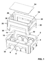
- the wiring accessory box of the invention comprises a parallelepiped base 2 with four side walls 4 and a bottom wall 6.
- Each side wall 4 comprises push-out regions 8 which, when removed, form the passageway for the flexible conduits.
- the bottom wall 6 comprises push-out regions 10 for other flexible conduits, and is also provided with gripping projections 12 for the mortar used to fix the base 2 into a recess previously formed in the masonry structure to which the box of the invention is to be applied.
- the corners of the base 2, perpendicular to the bottom wall 6, are slightly convex inwards, the centre of the convex part 14 being provided with an inner guide rib 16, the purpose of which will be apparent hereinafter.
- the box of the invention also comprises a support element for a traditional wiring insert plate.
- This support element is indicated overall by the number 18 and comprises a parallelepiped portion 20 provided with four guide feet 22.
- the parallelepiped structure 4 comprises four side walls and a push-out front closure portion 24, below which there are provided two small metal strips 26 applied to the two smaller side walls and centrally provided with a threaded hole 28.
- the four walls of the parallelepiped portion 20 also comprise a perimetral step 30, which surrounds the push-out front closure portion 24.
- Each of the two feet 22 presents a pair of ribs 32 positioned at 90° apart to embrace the corresponding convex portions 14 provided in the four corners of the base 2 and to hence guide the telescopic movements of the element 18 relative to the base 2, by virtue of the presence of the ribs 16.
- the dimensions of the mutually interacting parts are such as to make these telescopic movements possible, the longitudinal dimension of the element 18 being such that the distance between axes of the two holes 28 is equal to the distance between axes of the holes in the two metal strips provided in traditional wiring boxes, and hence also corresponds to the dimensions of traditional wiring insert plates.
- this latter is provided in its two larger side walls, in proximity to the convex corners 14, with longitudinal slots 34 along which corresponding appendices 36 provided at the free end of the feet 22 of the element 18 can slide.
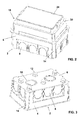
- the wiring accessory box of the invention is used in the following manner:
- the installer removes the push-out portions 8 through which other flexible conduits are to be passed, then inserts the support element 18 into the base 2.
- the support element 18 remains securely fixed to the base 2, although being able to slide telescopically relative thereto.
- the bricklayer arranges the element 18 with its push-out base 24 flush with the future finished surface of the plastered wall, during which the mortar may completely fill the perimetral step of the element 18, so stabilizing the element within the base 2, however it is unable to enter this latter because of the presence of the front wall 24.
- the push-out front wall 24 can be removed, to make the interior of the box formed by the base 2 and the support element 18 accessible, and at the same time making the strips 26 accessible to enable a traditional wiring insert plate (not shown) to be applied to them.
- wiring accessory box of the invention is particularly advantageous compared with traditional boxes, and in particular:
Landscapes
- Engineering & Computer Science (AREA)
- Architecture (AREA)
- Civil Engineering (AREA)
- Structural Engineering (AREA)
- Connection Or Junction Boxes (AREA)
Applications Claiming Priority (1)
| Application Number | Priority Date | Filing Date | Title |
|---|---|---|---|
| ITVE20050031 ITVE20050031A1 (it) | 2005-05-23 | 2005-05-23 | Scatola portafrutti per impianti elettrici.- |
Publications (2)
| Publication Number | Publication Date |
|---|---|
| EP1727254A2 true EP1727254A2 (fr) | 2006-11-29 |
| EP1727254A3 EP1727254A3 (fr) | 2010-07-28 |
Family
ID=37074257
Family Applications (1)
| Application Number | Title | Priority Date | Filing Date |
|---|---|---|---|
| EP06009928A Withdrawn EP1727254A3 (fr) | 2005-05-23 | 2006-05-15 | Boite de câblage pour accessoires d'installations électriques. |
Country Status (2)
| Country | Link |
|---|---|
| EP (1) | EP1727254A3 (fr) |
| IT (1) | ITVE20050031A1 (fr) |
Cited By (4)
| Publication number | Priority date | Publication date | Assignee | Title |
|---|---|---|---|---|
| CN106451262A (zh) * | 2015-08-11 | 2017-02-22 | 光阳工业股份有限公司 | 具有车用配线固定机构的壳体 |
| EP4007097A1 (fr) * | 2020-11-25 | 2022-06-01 | OBO Bettermann Hungary Kft. | Composant d'installation souterraine |
| US11557888B2 (en) | 2019-02-14 | 2023-01-17 | Erico International Corporation | Adjustable depth electrical wall mount ring |
| WO2023247440A1 (fr) * | 2022-06-20 | 2023-12-28 | Jpl Ev Ltd | Appareil et procédé de montage mural |
Family Cites Families (2)
| Publication number | Priority date | Publication date | Assignee | Title |
|---|---|---|---|---|
| US2378861A (en) * | 1944-04-20 | 1945-06-19 | Lafayette H Peevey | Outlet box extension |
| US4634015A (en) * | 1985-07-15 | 1987-01-06 | Taylor Jerald M | Adjustable electric outlet box |
-
2005
- 2005-05-23 IT ITVE20050031 patent/ITVE20050031A1/it unknown
-
2006
- 2006-05-15 EP EP06009928A patent/EP1727254A3/fr not_active Withdrawn
Cited By (5)
| Publication number | Priority date | Publication date | Assignee | Title |
|---|---|---|---|---|
| CN106451262A (zh) * | 2015-08-11 | 2017-02-22 | 光阳工业股份有限公司 | 具有车用配线固定机构的壳体 |
| CN106451262B (zh) * | 2015-08-11 | 2018-04-06 | 光阳工业股份有限公司 | 具有车用配线固定机构的壳体 |
| US11557888B2 (en) | 2019-02-14 | 2023-01-17 | Erico International Corporation | Adjustable depth electrical wall mount ring |
| EP4007097A1 (fr) * | 2020-11-25 | 2022-06-01 | OBO Bettermann Hungary Kft. | Composant d'installation souterraine |
| WO2023247440A1 (fr) * | 2022-06-20 | 2023-12-28 | Jpl Ev Ltd | Appareil et procédé de montage mural |
Also Published As
| Publication number | Publication date |
|---|---|
| EP1727254A3 (fr) | 2010-07-28 |
| ITVE20050031A1 (it) | 2006-11-24 |
Similar Documents
| Publication | Publication Date | Title |
|---|---|---|
| US7563978B2 (en) | Electrical box for concrete walls | |
| US7179993B2 (en) | Universal junction box with mounting aperture | |
| EP3378138B1 (fr) | Ensemble de montage ajustable | |
| US20140102745A1 (en) | Electrical Screw Extender | |
| EP1727254A2 (fr) | Boite de câblage pour accessoires d'installations électriques. | |
| US20230378732A1 (en) | Protective outlet cover | |
| US20050037646A1 (en) | Built-in electric contact enclosure and mounting method | |
| GB2408995A (en) | An electrical backbox plastering guide | |
| EP2816685A2 (fr) | Procédé de construction d'un module fonctionnel dans une paroi et ensemble à cet effet | |
| KR102218807B1 (ko) | 작업 편의성이 향상된 아웃렛박스 | |
| GB2392786A (en) | Preventing plaster entering back box | |
| EP1675237A2 (fr) | Dispositif de fixation pour boîtier de câblage | |
| GB2440184A (en) | Electrical accessory box comprising stop member | |
| FI3675300T3 (fi) | Sovitin asennuskotelon asettamiseksi ja kiinnittämiseksi | |
| GB2457520A (en) | Safety shield for electrical back box | |
| EP2824782B1 (fr) | Boîtier de montage de construction dans une paroi et procédure pour la construction d'un tel boîtier de montage | |
| US20240133195A1 (en) | Protective cover | |
| KR200300947Y1 (ko) | 옥내 배선용 접속함 | |
| JP3204422U (ja) | 布板規制具 | |
| GB2343908A (en) | Plastering method and device for electrical wall boxes | |
| GB2118378A (en) | Improvements in fixings | |
| JPS5934040Y2 (ja) | 回路しや断器の端子カバ− | |
| BE1022718B1 (nl) | Ophoogkader voor een inbouwdoos voor de montage van elektrotechnische componenten in een muur en werkwijze voor het monteren van een elektrotechnische component in een muur | |
| WO2024003901A1 (fr) | Unité de montage d'installation à fleur | |
| HK1232341A1 (en) | Electrical back box for mounting within a substantially circular hole |
Legal Events
| Date | Code | Title | Description |
|---|---|---|---|
| PUAI | Public reference made under article 153(3) epc to a published international application that has entered the european phase |
Free format text: ORIGINAL CODE: 0009012 |
|
| AK | Designated contracting states |
Kind code of ref document: A2 Designated state(s): AT BE BG CH CY CZ DE DK EE ES FI FR GB GR HU IE IS IT LI LT LU LV MC NL PL PT RO SE SI SK TR |
|
| AX | Request for extension of the european patent |
Extension state: AL BA HR MK YU |
|
| PUAL | Search report despatched |
Free format text: ORIGINAL CODE: 0009013 |
|
| AK | Designated contracting states |
Kind code of ref document: A3 Designated state(s): AT BE BG CH CY CZ DE DK EE ES FI FR GB GR HU IE IS IT LI LT LU LV MC NL PL PT RO SE SI SK TR |
|
| AX | Request for extension of the european patent |
Extension state: AL BA HR MK YU |
|
| AKY | No designation fees paid | ||
| REG | Reference to a national code |
Ref country code: DE Ref legal event code: R108 Effective date: 20110309 Ref country code: DE Ref legal event code: 8566 |
|
| STAA | Information on the status of an ep patent application or granted ep patent |
Free format text: STATUS: THE APPLICATION IS DEEMED TO BE WITHDRAWN |
|
| 18D | Application deemed to be withdrawn |
Effective date: 20101221 |