EP1727256A2 - Système et méthode d'enceinte - Google Patents
Système et méthode d'enceinte Download PDFInfo
- Publication number
- EP1727256A2 EP1727256A2 EP06252689A EP06252689A EP1727256A2 EP 1727256 A2 EP1727256 A2 EP 1727256A2 EP 06252689 A EP06252689 A EP 06252689A EP 06252689 A EP06252689 A EP 06252689A EP 1727256 A2 EP1727256 A2 EP 1727256A2
- Authority
- EP
- European Patent Office
- Prior art keywords
- enclosure
- enclosure apparatus
- patch member
- location
- communication device
- Prior art date
- Legal status (The legal status is an assumption and is not a legal conclusion. Google has not performed a legal analysis and makes no representation as to the accuracy of the status listed.)
- Withdrawn
Links
- 238000000034 method Methods 0.000 title claims description 10
- 238000004891 communication Methods 0.000 claims abstract description 55
- 230000004888 barrier function Effects 0.000 claims description 14
- 238000001816 cooling Methods 0.000 claims description 5
- 230000008569 process Effects 0.000 claims description 5
- 239000002184 metal Substances 0.000 claims description 3
- 229910052751 metal Inorganic materials 0.000 claims description 3
- 239000013307 optical fiber Substances 0.000 claims description 3
- 230000005540 biological transmission Effects 0.000 claims description 2
- 229920003023 plastic Polymers 0.000 claims description 2
- 239000004033 plastic Substances 0.000 claims description 2
- 238000001514 detection method Methods 0.000 claims 1
- 238000010438 heat treatment Methods 0.000 claims 1
- 238000012545 processing Methods 0.000 abstract description 3
- 239000000463 material Substances 0.000 description 3
- 230000008901 benefit Effects 0.000 description 2
- 238000009413 insulation Methods 0.000 description 2
- 238000012423 maintenance Methods 0.000 description 2
- 230000001681 protective effect Effects 0.000 description 2
- 230000004075 alteration Effects 0.000 description 1
- 230000008867 communication pathway Effects 0.000 description 1
- 229910052802 copper Inorganic materials 0.000 description 1
- 239000010949 copper Substances 0.000 description 1
- 238000013461 design Methods 0.000 description 1
- 230000007613 environmental effect Effects 0.000 description 1
- 230000036039 immunity Effects 0.000 description 1
- 238000009434 installation Methods 0.000 description 1
- 230000037361 pathway Effects 0.000 description 1
- 230000035515 penetration Effects 0.000 description 1
- 230000002093 peripheral effect Effects 0.000 description 1
- 229920000915 polyvinyl chloride Polymers 0.000 description 1
- 239000004800 polyvinyl chloride Substances 0.000 description 1
- 238000010079 rubber tapping Methods 0.000 description 1
- 230000035939 shock Effects 0.000 description 1
- 238000013519 translation Methods 0.000 description 1
Images



Classifications
-
- H—ELECTRICITY
- H04—ELECTRIC COMMUNICATION TECHNIQUE
- H04Q—SELECTING
- H04Q1/00—Details of selecting apparatus or arrangements
- H04Q1/02—Constructional details
- H04Q1/13—Patch panels for monitoring, interconnecting or testing circuits, e.g. patch bay, patch field or jack field; Patching modules
-
- H—ELECTRICITY
- H04—ELECTRIC COMMUNICATION TECHNIQUE
- H04Q—SELECTING
- H04Q1/00—Details of selecting apparatus or arrangements
- H04Q1/02—Constructional details
- H04Q1/035—Cooling of active equipments, e.g. air ducts
-
- H—ELECTRICITY
- H04—ELECTRIC COMMUNICATION TECHNIQUE
- H04Q—SELECTING
- H04Q1/00—Details of selecting apparatus or arrangements
- H04Q1/02—Constructional details
- H04Q1/06—Cable ducts or mountings specially adapted for exchange installations
-
- H—ELECTRICITY
- H04—ELECTRIC COMMUNICATION TECHNIQUE
- H04Q—SELECTING
- H04Q1/00—Details of selecting apparatus or arrangements
- H04Q1/02—Constructional details
- H04Q1/11—Protection against environment
- H04Q1/116—Protection against environment lightning or EMI protection, e.g. shielding or grounding
-
- H—ELECTRICITY
- H04—ELECTRIC COMMUNICATION TECHNIQUE
- H04Q—SELECTING
- H04Q2201/00—Constructional details of selecting arrangements
- H04Q2201/08—Pivotable parts
-
- H—ELECTRICITY
- H04—ELECTRIC COMMUNICATION TECHNIQUE
- H04Q—SELECTING
- H04Q2201/00—Constructional details of selecting arrangements
- H04Q2201/10—Housing details
-
- H—ELECTRICITY
- H04—ELECTRIC COMMUNICATION TECHNIQUE
- H04Q—SELECTING
- H04Q2201/00—Constructional details of selecting arrangements
- H04Q2201/14—Screening, grounding or crosstalk reduction details
Definitions
- This invention relates to an enclosure apparatus and more particularly to an enclosure apparatus associated with electrical equipment and cable connections.
- enclosures often called “zone boxes,” house electrical connectors adapted to receive cables extending from the telecommunications equipment, typically positioned in locations remote from the zone boxes. Additional cables may extend out of the electrical connectors to specific work or coverage areas, to establish connections with a mix of local devices, such as personal computers, printers, workstations and certain video cameras.
- Still additional enclosures may house communication devices, such as application specific control devices, adapted to process data received from remote locations, such as the telecommunications room or other remote locations where local devices, such as building automation equipment, reside.
- the communication devices connect to zone boxes on the one hand and directly to the local devices on the other. In this way, two-way communication between the telecommunications room and local device may be established and maintained. Cable pathways, such as conduits, raceways, trays or ladders are often used to route these cables.
- buildings utilize multiple enclosures for various devices, with cables running from the telecommunications room to zone box enclosures and cables running from various local devices to communication devices housed in other enclosures.
- This configuration results in a higher initial quantity of required materials, more initial installation labor, and more costly implementation of ongoing moves and changes to building systems.
- the enclosure apparatus is preferably easy to use and adapt to various building environments.
- the present invention relates to an improved enclosure apparatus as well as systems and methods for using the same.
- the enclosure apparatus comprises a single receptacle comprising a base member mountable to a building structure and walls connected to the base member, a moveable patch member positioned within the single receptacle and at least one communication device comprising a microprocessor positioned within the single receptacle.
- the patch member is connected to at least one data cable, which enters the single receptacle from a first location remote therefrom and the communication device is connected to the patch member.
- the enclosure apparatus comprises a single receptacle comprising a base member mountable to a building structure and top, bottom and side walls connected to the base member, at least one aperture defined in at least one of base member and the walls for receiving one or more cables, at least one patch member positioned within the single receptacle and at least one cable separator comprising a barrier wall positioned within the receptacle and extending in a direction generally parallel to the side walls of the receptacle.
- the patch member may be electrically connected to the one or more cables.
- the enclosure apparatus of the present invention comprises a single receptacle comprising a base member mountable to a building structure and walls connected to the base member, a moveable patch member positioned within the single receptacle and a mounting device adapted to receive at least one communication device, the communication device capable of being connected to at least one data cable through the patch member.
- the patch member may be connected to the at least one data cable, which enters the single receptacle from a first location remote therefrom.
- the enclosure apparatus may incorporate additional features and structure.
- the walls of the receptacle may define apertures for receiving the at least one data cable.
- the patch member may further comprise at least one electrical connector comprising at least one of co-axial connectors, D-sub-mini connectors, punch-down connectors, optical fiber connectors and rack mounting modular ethernet connectors.
- the communication device may comprise a controller or sensor and the microprocessor may be adapted to process data received from the first remote location.
- the apparatus may further comprise a mounting device comprising a plurality of regularly spaced apertures and/or a cable separator comprising a barrier wall for providing a dielectric barrier between adjacent cables. Two or more opposing barrier walls may define a channel therebetween, which is protectible with a hinged cover. These barriers may also be configured to form an inverted U-shape to help separate the patch member from the communication devices.
- the enclosure apparatus may further comprise a restraint for confining movement of cables in a radial direction.
- the present invention is directed to systems for data transmission.
- the system comprises electrical equipment positioned within a first location and connected to at least one data cable and a single receptacle remote from the first location.
- the single receptacle comprises a base member mountable to a plenum in a building structure and walls connected to the base member, a patch member and at least one communication device comprising a microprocessor, wherein the patch member and the communication device are connected to the at least one data cable, with the communication device being connected to the at least one data cable through the patch member.
- the communication device is adapted to receive data from the electrical equipment, process the data and transmit a communication based on the processed data to at least one of the electrical equipment in the first location and a second location within the building.
- the second location is remote from the first location and the single receptacle and may comprise building automation equipment.
- the system may also include various other components.
- the walls of the single receptacle may comprise a grounding stud and a vent.
- the at least one data cable may be an ethernet data cable.
- the communication device may comprise one of a controller and a sensor and communicate wirelessly with other devices within the building.
- the system can further comprise a mounting device positioned within the receptacle for receiving and carrying the communication device.
- the enclosure of the present invention may also be used in methods for wiring a building.
- the method may comprise providing a single enclosure comprising at least one patch member and at least one communication device, connecting a first cable extending from a central communication area to the patch member and connecting a second cable from the at least one patch member to the at least one communication device.
- Fig. 1 is a perspective view of one embodiment of the enclosure apparatus of the present invention for routing cables within a building;
- Fig. 2 is a perspective view of the invention of Fig. 1, showing the hinged patch member in its downward position, without cabling or controls being shown;
- Fig. 3A is a front elevational view of the present invention of Fig. 1;
- Fig. 3B is an enlarged view of the mounting board shown in Fig. 3A;
- Fig. 4 is a front perspective view of the enclosure apparatus of the present invention, further comprising cable separators;
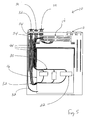
- Fig. 5 is a front elevational view of the enclosure apparatus of the present invention, showing the cable separators of Fig. 4;
- Fig. 6 is a schematic view of one embodiment of the system of the present invention.
- the present invention relates to an enclosure apparatus and a system or method for employing the same.
- the enclosure apparatus includes a single receptacle comprising a base member mountable to a building and walls connected to the base member.
- a moveable patch member connected to at least one data cable from a remote location may be positioned within the single receptacle.
- One or more communication devices connected to the at least one data cable through the patch member may also reside in the single receptacle.
- the one or more communication devices may comprise low voltage equipment, such as controllers for operating local devices, including building automation equipment, or high voltage equipment. Cables associated with the low and high voltage equipment may extend into and connect with the patch member.
- the enclosure may be mounted on a wall, or within the ceiling or floor of a building.
- Enclosure apparatus 10 may include receptacle 11, door 12, moveable patch member 14, mounting device 16, at least one cooling port 18 and communication devices 22.
- patch member 14 means any device for holding electrical connectors used with cables.
- the distance d between patch member 14 and communication devices 22 is between about 1.0 inch to about 60.0 inches and more particularly, between about 6.0 inches to about 25.0 inches.
- Enclosure 10 comprises receptacle 11, which includes base member 13 and walls 15.
- Receptacle 11 may further comprise upper portion 23 and lower portion 24.
- Base member 13 may be adapted for mounting on a building structure and may comprise brackets, fasteners and the like.
- Walls 15 may comprise top wall 25, bottom wall 27 and side walls 29.
- Upper portion 23 typically comprises patch member 14, though patch member 14 can be located in various locations throughout enclosure 10.
- Lower portion 24 typically comprises mounting panel 16, which can also be located throughout enclosure 10.
- Each of top wall 25, bottom wall 27 and side walls 29 may comprise knockouts or apertures 31 for receiving cables from electrical equipment in remote locations.
- Electrical equipment in a first remote location may, for example, include telecommunications equipment in a telecommunications room, a main server or building automation equipment located throughout the building.
- Door 12 may be hinged or screwed to enclosure 10.
- Door 12 optionally includes window 26 for viewing electrical components once they have been installed in enclosure 10.
- Door 12 may also include lock assembly (not shown) to prevent tampering with electrical components.
- Patch member 14 may take the form of a modular patch panel, punch-down wiring blocks, combinations thereof or the like.
- Patch member 14 may comprise electrical connectors 30, including coaxial connectors, D sub mini connectors, optical fiber connectors and rack mounting modular ethernet connectors, such as RJ45 jacks, punch-down formats and the like.
- First cables 32 may extend to connectors 30 of patch member 14 from the above-described electrical equipment positioned in remote locations.
- Second cables 33 may extend from patch member 14 to and from communication devices 22.
- moveable patch member 14 may include hinge 35 to tilt downwardly, thereby allowing easy access to cables 32 entering from both the front and rear of patch member 14. This configuration allows physical access to the rear of the cable connections so that installers and maintenance personnel can see the hardware and avoid working on connections concealed from sight.
- mounting device 16 may comprise a panel carrying a plurality of mounting apertures 36, adapted to receive communication devices 22.
- Mounting device 16 can quickly accommodate varied equipment packages with various fasterners known to those of skill in the art.
- self-tapping screws may be employed with mounting arrangements such as flanged housings and DIN rails.
- mounting device 16 occupies virtually the entire inside area of enclosure 10, to allow various patch elements, such as standard rack unit bracketry, punch down blocks or the like to mount directly on mounting device 16.
- Mounting device 16 may also simply comprise a bracket.
- Cooling ports 18 are adapted to cool active electronic equipment positioned within enclosure 10.
- Enclosure 10 may also include mounting provisions for forced cooling fans or the like.
- communication devices 22 may comprise one or both of low and high voltage equipment.
- Communication devices 22 typically comprise microprocessor 21 for processing data received over first cables 32 from a first location remote from the enclosure apparatus.
- Communication devices 22 are also adapted to transmit a communication based on the processed data to either the source of the data at the first remote location or other devices positioned at second locations remote from the first location and enclosure apparatus 10. It bears noting that devices in the first and second remote locations may be hard-wired directly into communication devices 22 within receptacle 11 or communicate wirelessly therewith via electrical or radio frequency signals. Under these circumstances, communication devices 22 still typically remain connected to patch member 14 for connectivity to still other remote locations.
- Various types of low voltage equipment may be employed.
- Low voltage equipment may, for example, include controllers, such as programmable logic controllers, access control modules, HVAC controllers or lighting controllers and sensing devices, such as environmental sensors or radio transceivers with remote antennas.
- controllers such as programmable logic controllers, access control modules, HVAC controllers or lighting controllers and sensing devices, such as environmental sensors or radio transceivers with remote antennas.
- low voltage equipment may include screw terminal blocks, din rail mounted equipment, punchdown blocks for data cabling, rack mount brackets, equipment, switches or patch panels, relays, data acquisition units, fiber-to-copper media converters, protocol mediator boxes, power supplies and graphic displays.
- This low voltage equipment is often connected to local devices 37, such as building automation equipment (e.g ., HVAC, physical access control, fire and video surveillance, lighting, paging, clock systems and the like).
- High voltage equipment 38 can include screw terminal blocks, power disconnect switches, cabinet lighting, fuse blocks, circuit breakers, transformers, high voltage barrier switches or power strips. Although high voltage equipment 38 may be connected to patch member 14, some high voltage equipment 38, typically positioned in lower portion 24 of enclosure 10, may not be so connected. In addition, high voltage equipment may be connected to communication devices 22, as a source of power. Protective barriers may enclose at least a portion of high voltage equipment to help prevent electrical discharge or shock. Protective barriers may be metallic, dielectric or transparent dielectric.
- Grounding stud 40 may also optionally be added to enclosure 10.
- the purpose of grounding stud 40 is to ground enclosure apparatus 10 to avoid unwanted electric discharge.
- enclosure 10 may comprise knockouts or apertures 31 and cable separators 42 for receiving and managing these cables.
- Knockouts 31 comprise apertures adapted to receive incoming cables from remote locations and may be positioned on base member 13, top wall 25, bottom wall 27 side walls 29 of receptacle 11. Knockouts 31 are preferably arranged so that cable bundles do not criss-cross.
- cable separators 42 comprising at least one barrier wall, are designed to separate and provide a dielectric barrier between adjacent first and second cables 32 and 33 and may be constructed of one of plastic, such as polyvinyl chloride, or metal.
- Separators 42 segregate cables 32 and 33 from a point of entry at knockouts 31 to at or near communication devices 22 to which cables 32 and 33 may be connected.
- Separators 42 advantageously prevent high voltage cables (e.g ., cables calling for 600Vrms insulation) from physically contacting low voltage cables (e.g ., cables calling for 300Vrms insulation).
- Separators 42 may comprise opposing walls defining channels 50 therebetween. Channels 50 are typically aligned with knockouts 31 along an axis a and hinged cover 52 may be positioned over channel 50 to secure cables 32 and 33 between opposing walls.
- Cable separators 42 are variable. Cable separators 42 are typically positioned parallel to side wall 29 of receptacle 11. Separators 42 may also be configured to form an inverted U-shape, as shown in Figs. 4 and 5. This orientation separates patch member 14 and communication device 22 and prevents cables 32 and 33 from contacting communication devices 22 and high voltage equipment 38.
- restraints 54 may be provided. Restraints 54 help confine movement of cables 32 and 33 in a radial direction and are typically positioned adjacent patch member 14. When sufficient cable slack is provided for patch member 14, as shown in Fig. 5, movement of patch member 14 does not displace entire cable bundles within channels 50. Additionally, restraints 54 can prevent translation of cable bundles when unwanted pulling of single cables 32 and 33 occurs. Restraint 54 may comprise a cable tie.
- Enclosure 10 is particularly useful for building automation equipment employing ethernet communication pathways. Ethernet cables may extend from building automation equipment to patch members 14 and communication devices 22, all of which are positioned within single receptacle 11.
- Enclosure 10 and mounting panel 16 may be constructed of metal or other similar materials known to those of skill in the art. These parts may be machined. Hinged patch member 14 may be installed and the dimensions of communication devices 22 and may be calculated to determine their respective positioning within enclosure. Thereafter, these components may be mounted on mounting device 16 within enclosure 10.
- enclosure 10 After enclosure 10 is fabricated, it may be mounted on a wall or within a plenum space of a building.
- Plenum as used herein, means an enclosed space used to affect air distribution within a building, such as beneath the floor or within the ceiling. Often, the space beneath the floor or between a structural ceiling and a drop ceiling is used as plenum space in a building's HVAC design.
- enclosure 10 When enclosure 10 is positioned within such plenum space, it is typically mounted on a bottom surface of the floor or on the structural ceiling. Cable penetration into enclosure 10 may be sealed with a compressed gasket to prevent airflow within enclosure 10 from exiting into the plenum space. Thus, cooling ports 18 and like components for air exchange between the interior of enclosure 10 and plenum space may be eliminated from enclosure 10. Other alterations to enclosure 10 may also be made.
- door 12 When enclosure 10 is positioned within a ceiling, for example, door 12 may be hinged to a bottom portion of enclosure 10, with electrical components mounted to door 12, for ease of access.
- patch member 14 After enclosure is mounted, patch member 14 is tilted downward about its hinge (Fig. 3), and, as shown in Fig. 1, incoming first cables 32 extending from telecommunications equipment in locations remote from enclosure apparatus 10 are releasably secured to a rear of patch member 14. Second cables 33 extending from communication device 22 may be releasably secured to a front of patch member 14. When cable separators 44 are employed, first and second cables 32 and 33 may be positioned in channels 50 to prevent comingling of high and low voltage cabling. Connection points for the cabling may, however, be reversed.
- first cables 32 extending from a telecommunications room extend into a single receptacle 11, which also includes communication devices 22.
- First cables 32 extending from the telecommunications equipment and second cables 33 extending from communication devices 22 may connect with at least one electrical connector positioned within patch member 14. These connections may or may not comprise ethernet communications.
- the enclosure apparatus 10 of the present invention may provide a number of advantages. By eliminating separate boxes ⁇ one for patch member 14 and the other for communication devices 22 ⁇ enclosure space, material cost, and labor cost can be saved. This configuration may also provide increased immunity to radiofrequency interference, since cables extending from low voltage equipment to a zone box benefit from the protection of the conductive enclosure rather than exposure to the external environment. Enclosure 10 also facilitates maintenance, as personnel have quicker access to various components within a single enclosure. Similarly, moves, adds, and changes become simplified, since the evolution and adoption of ethernet enabled actuators, sensors, and other end devices require less disassembly and removal of legacy equipment. Removal of abandoned application specific control elements from the inventive zone enclosure results in additional space for ethernet equipment such as midspan power injectors, switches, patch panels, power splitters, and other peripherals.
Landscapes
- Engineering & Computer Science (AREA)
- Computer Networks & Wireless Communication (AREA)
- Health & Medical Sciences (AREA)
- Toxicology (AREA)
- Installation Of Indoor Wiring (AREA)
- Casings For Electric Apparatus (AREA)
- Structure Of Telephone Exchanges (AREA)
- Distribution Board (AREA)
- Connections By Means Of Piercing Elements, Nuts, Or Screws (AREA)
Applications Claiming Priority (2)
| Application Number | Priority Date | Filing Date | Title |
|---|---|---|---|
| US68408505P | 2005-05-24 | 2005-05-24 | |
| US11/383,667 US7737360B2 (en) | 2005-05-24 | 2006-05-16 | Enclosure apparatus, system and method |
Publications (2)
| Publication Number | Publication Date |
|---|---|
| EP1727256A2 true EP1727256A2 (fr) | 2006-11-29 |
| EP1727256A3 EP1727256A3 (fr) | 2010-12-29 |
Family
ID=36950930
Family Applications (1)
| Application Number | Title | Priority Date | Filing Date |
|---|---|---|---|
| EP06252689A Withdrawn EP1727256A3 (fr) | 2005-05-24 | 2006-05-24 | Système et méthode d'enceinte |
Country Status (3)
| Country | Link |
|---|---|
| US (1) | US7737360B2 (fr) |
| EP (1) | EP1727256A3 (fr) |
| JP (1) | JP2006340595A (fr) |
Families Citing this family (81)
| Publication number | Priority date | Publication date | Assignee | Title |
|---|---|---|---|---|
| US7035773B2 (en) * | 2002-03-06 | 2006-04-25 | Fisher-Rosemount Systems, Inc. | Appendable system and devices for data acquisition, analysis and control |
| US7459961B2 (en) * | 2006-10-31 | 2008-12-02 | Avago Technologies Wireless Ip (Singapore) Pte. Ltd. | Voltage supply insensitive bias circuits |
| US12185512B2 (en) | 2007-11-16 | 2024-12-31 | Manufacturing Resources International, Inc. | Electronic display assembly with thermal management |
| US8854595B2 (en) | 2008-03-03 | 2014-10-07 | Manufacturing Resources International, Inc. | Constricted convection cooling system for an electronic display |
| US8654302B2 (en) | 2008-03-03 | 2014-02-18 | Manufacturing Resources International, Inc. | Heat exchanger for an electronic display |
| US10827656B2 (en) | 2008-12-18 | 2020-11-03 | Manufacturing Resources International, Inc. | System for cooling an electronic image assembly with circulating gas and ambient gas |
| US8749749B2 (en) | 2008-12-18 | 2014-06-10 | Manufacturing Resources International, Inc. | System for cooling an electronic image assembly with manifolds and ambient gas |
| US8031471B2 (en) * | 2008-12-19 | 2011-10-04 | Just Encase Products, Inc. | Secure transparent enclosure for communication device |
| US8461453B2 (en) * | 2009-01-27 | 2013-06-11 | Connector Manufacturing Company | Wind turbine wiring enclosure cabinet |
| US8143519B2 (en) * | 2009-01-27 | 2012-03-27 | Connector Manufacturing Company | Integral wind turbine wiring enclosure cabinet |
| US9812047B2 (en) | 2010-02-25 | 2017-11-07 | Manufacturing Resources International, Inc. | System and method for remotely monitoring the operating life of electronic displays |
| TW201039506A (en) * | 2009-04-24 | 2010-11-01 | Au Optronics Corp | Shielding device and display device having the same |
| US8687350B2 (en) * | 2011-05-11 | 2014-04-01 | Ez-Tech Corp | Motherboard and case with hidden internal connectors |
| US9134496B2 (en) * | 2011-05-19 | 2015-09-15 | Communication Systems, Inc. | Modular plug and play connectivity platform |
| US9678162B2 (en) * | 2011-11-04 | 2017-06-13 | Kohler Co. | Load control module that permits testing of power switching devices that are part of the load control module |
| US8785771B2 (en) * | 2012-01-26 | 2014-07-22 | William Dunkleberger | Zonal utility control system |
| US20140094057A1 (en) * | 2012-10-01 | 2014-04-03 | Panduit Corp. | Modular Patch Panel System |
| US9615470B2 (en) * | 2012-10-03 | 2017-04-04 | Sunlink Corporation | Wiring combiner box |
| US8987594B1 (en) * | 2012-10-16 | 2015-03-24 | The Boeing Company | Reconfigurable multiple interconnection device and method |
| USD702198S1 (en) * | 2013-01-09 | 2014-04-08 | Arlington Industries, Inc. | Electrical enclosure box |
| US9142921B2 (en) | 2013-02-27 | 2015-09-22 | Molex Incorporated | High speed bypass cable for use with backplanes |
| NL2010624C2 (en) * | 2013-04-08 | 2014-10-09 | Mapper Lithography Ip Bv | Cabinet for electronic equipment. |
| CN104582378A (zh) * | 2013-10-29 | 2015-04-29 | 鸿富锦精密电子(天津)有限公司 | 机柜 |
| EP3138372B1 (fr) | 2014-04-30 | 2019-05-08 | Manufacturing Resources International, INC. | Ensemble d'affichage électronique dos à dos |
| US9952397B2 (en) | 2014-09-23 | 2018-04-24 | Ppc Broadband Inc. | Universal multi-purpose compartmentalized telecommunications box |
| US10976512B2 (en) | 2014-09-23 | 2021-04-13 | Ppc Broadband, Inc. | House box with mounting surface for mounted access |
| US10509187B2 (en) | 2014-09-23 | 2019-12-17 | Ppc Broadband, Inc. | Universal multi-purpose compartmentalized telecommunications box |
| US9882362B2 (en) | 2014-09-23 | 2018-01-30 | Ppc Broadband, Inc. | Enclosure for controling access to different telecommunication components |
| AU2015360514B2 (en) * | 2014-12-09 | 2020-04-23 | Ppc Broadband, Inc. | Universal multi-purpose compartmentalized telecommunication box |
| CN110662388A (zh) | 2015-01-11 | 2020-01-07 | 莫列斯有限公司 | 模块壳体及连接器端口 |
| KR20170102011A (ko) | 2015-01-11 | 2017-09-06 | 몰렉스 엘엘씨 | 바이패스 루트설정 조립체에 사용하기 적합한 와이어-대-기판 커넥터 |
| US9723765B2 (en) | 2015-02-17 | 2017-08-01 | Manufacturing Resources International, Inc. | Perimeter ventilation system for electronic display |
| CN104822043A (zh) * | 2015-04-15 | 2015-08-05 | 江苏中兴新泰物联网科技园有限公司 | 一种远程无线数字化城市管理装置 |
| WO2016179263A1 (fr) * | 2015-05-04 | 2016-11-10 | Molex, Llc | Dispositif informatique utilisant un ensemble dérivation |
| AU2016321400B2 (en) | 2015-09-10 | 2019-05-30 | Manufacturing Resources International, Inc. | System and method for systemic detection of display errors |
| KR102092627B1 (ko) | 2016-01-11 | 2020-03-24 | 몰렉스 엘엘씨 | 루트설정 조립체 및 이를 사용한 시스템 |
| CN108475870B (zh) | 2016-01-19 | 2019-10-18 | 莫列斯有限公司 | 集成路由组件以及采用集成路由组件的系统 |
| US10820445B2 (en) | 2016-03-04 | 2020-10-27 | Manufacturing Resources International, Inc. | Cooling system for double sided display assembly |
| CN106159826B (zh) * | 2016-07-14 | 2018-06-29 | 常熟市亚邦船舶电气有限公司 | 一种双控制板的控制盒 |
| US10485113B2 (en) | 2017-04-27 | 2019-11-19 | Manufacturing Resources International, Inc. | Field serviceable and replaceable display |
| WO2018200905A1 (fr) | 2017-04-27 | 2018-11-01 | Manufacturing Resources International, Inc. | Système et procédé permettant d'empêcher un gauchissement de dispositif d'affichage |
| KR102369614B1 (ko) * | 2017-09-05 | 2022-03-03 | 삼성전자주식회사 | 방수 구조를 포함하는 전자 장치 |
| EP3679414A4 (fr) | 2017-09-08 | 2021-05-05 | Commscope Technologies LLC | Enceinte de dissipation de chaleur |
| US11645029B2 (en) | 2018-07-12 | 2023-05-09 | Manufacturing Resources International, Inc. | Systems and methods for remotely monitoring electronic displays |
| US10908863B2 (en) | 2018-07-12 | 2021-02-02 | Manufacturing Resources International, Inc. | System and method for providing access to co-located operations data for an electronic display |
| US10602626B2 (en) | 2018-07-30 | 2020-03-24 | Manufacturing Resources International, Inc. | Housing assembly for an integrated display unit |
| US10581231B1 (en) * | 2018-09-18 | 2020-03-03 | Sergio Perez | Electrical panel assembly |
| CN110933891B (zh) * | 2018-09-19 | 2022-05-06 | 台达电子工业股份有限公司 | 户外型无线电子装置的防水外壳 |
| USD909320S1 (en) * | 2018-10-04 | 2021-02-02 | ROLEC Gehäuse-Systeme GmbH | Housing for electric and electronic components |
| US11082314B2 (en) * | 2018-10-08 | 2021-08-03 | Ampthink, Llc | Electronic components enclosure located in a step structure |
| US11228167B2 (en) * | 2018-11-13 | 2022-01-18 | Leviton Manufacturing Co., Inc. | Adjustable insert system for wall-mounted enclosures |
| US11402940B2 (en) | 2019-02-25 | 2022-08-02 | Manufacturing Resources International, Inc. | Monitoring the status of a touchscreen |
| WO2020176416A1 (fr) | 2019-02-25 | 2020-09-03 | Manufacturing Resources International, Inc. | Surveillance de l'état d'un écran tactile |
| US11096317B2 (en) | 2019-02-26 | 2021-08-17 | Manufacturing Resources International, Inc. | Display assembly with loopback cooling |
| US10795413B1 (en) | 2019-04-03 | 2020-10-06 | Manufacturing Resources International, Inc. | Electronic display assembly with a channel for ambient air in an access panel |
| US11172586B2 (en) * | 2019-04-09 | 2021-11-09 | Richard Hermann | Modular multipurpose telecommunications enclosure |
| US11432168B2 (en) * | 2020-05-04 | 2022-08-30 | Lennox Industries Inc. | Self-configuring multiple-antenna system |
| US11477923B2 (en) | 2020-10-02 | 2022-10-18 | Manufacturing Resources International, Inc. | Field customizable airflow system for a communications box |
| US11470749B2 (en) | 2020-10-23 | 2022-10-11 | Manufacturing Resources International, Inc. | Forced air cooling for display assemblies using centrifugal fans |
| US11778757B2 (en) | 2020-10-23 | 2023-10-03 | Manufacturing Resources International, Inc. | Display assemblies incorporating electric vehicle charging equipment |
| CN114498506A (zh) * | 2020-10-26 | 2022-05-13 | 周雅娟 | 一种母线插接系统 |
| US11445633B2 (en) * | 2021-01-14 | 2022-09-13 | Super Micro Computer, Inc. | Telecommunication cabinet with hidden anti-theft heat dissipation module |
| US12116027B2 (en) * | 2021-06-22 | 2024-10-15 | C.D.L. Electric Company, Inc. | Railway shunt enclosure |
| US11965804B2 (en) | 2021-07-28 | 2024-04-23 | Manufacturing Resources International, Inc. | Display assemblies with differential pressure sensors |
| US11921010B2 (en) | 2021-07-28 | 2024-03-05 | Manufacturing Resources International, Inc. | Display assemblies with differential pressure sensors |
| US12408312B2 (en) | 2021-07-28 | 2025-09-02 | Manufacturing Resources International, Inc. | Display assemblies with vents |
| US11966263B2 (en) | 2021-07-28 | 2024-04-23 | Manufacturing Resources International, Inc. | Display assemblies for providing compressive forces at electronic display layers |
| US11762231B2 (en) | 2021-08-23 | 2023-09-19 | Manufacturing Resources International, Inc. | Display assemblies inducing turbulent flow |
| US11919393B2 (en) | 2021-08-23 | 2024-03-05 | Manufacturing Resources International, Inc. | Display assemblies inducing relatively turbulent flow and integrating electric vehicle charging equipment |
| US11744054B2 (en) | 2021-08-23 | 2023-08-29 | Manufacturing Resources International, Inc. | Fan unit for providing improved airflow within display assemblies |
| US12567728B2 (en) * | 2021-09-12 | 2026-03-03 | Splitvolt, Inc. | Power sharing device |
| US11968813B2 (en) | 2021-11-23 | 2024-04-23 | Manufacturing Resources International, Inc. | Display assembly with divided interior space |
| US12119597B2 (en) * | 2022-05-19 | 2024-10-15 | James Brown | Electrical junction box assembly |
| US12010813B2 (en) | 2022-07-22 | 2024-06-11 | Manufacturing Resources International, Inc. | Self-contained electronic display assembly, mounting structure and methods for the same |
| US12072561B2 (en) | 2022-07-22 | 2024-08-27 | Manufacturing Resources International, Inc. | Self-contained electronic display assembly, mounting structure and methods for the same |
| US12035486B1 (en) | 2022-07-25 | 2024-07-09 | Manufacturing Resources International, Inc. | Electronic display assembly with fabric panel communications box |
| US11972672B1 (en) | 2022-10-26 | 2024-04-30 | Manufacturing Resources International, Inc. | Display assemblies providing open and unlatched alerts, systems and methods for the same |
| US12027132B1 (en) | 2023-06-27 | 2024-07-02 | Manufacturing Resources International, Inc. | Display units with automated power governing |
| US12598727B2 (en) | 2024-01-09 | 2026-04-07 | Manufacturing Resources International, Inc. | Double sided display assembly with bi-directional flow through a common, partitioned heat exchanger |
| WO2025212305A1 (fr) | 2024-04-04 | 2025-10-09 | Manufacturing Resources International, Inc. | Ensemble d'affichage utilisant des données de caractéristiques d'air pour vérifier des conditions de fonctionnement d'ensemble d'affichage, et systèmes et procédés associés |
| US20250323473A1 (en) * | 2024-04-10 | 2025-10-16 | Dbt holdings LLC | Enclosure for Electrical Interface |
Family Cites Families (7)
| Publication number | Priority date | Publication date | Assignee | Title |
|---|---|---|---|---|
| SE505801C2 (sv) * | 1992-09-25 | 1997-10-13 | Atlas Copco Tools Ab | Skåp för inrymmande av elektronisk utrustning anslutbar till maskiner eller kraftverktyg |
| US5573321A (en) * | 1995-06-21 | 1996-11-12 | Bell, Jr.; George W. | Access frame for electrical enclosure |
| US5721394A (en) * | 1996-07-12 | 1998-02-24 | Mulks; Robert | Flush mount multiport connection box |
| US6132242A (en) * | 1997-01-08 | 2000-10-17 | The Whitaker Corporation | Distribution device for wiring |
| US6788786B1 (en) * | 2000-09-22 | 2004-09-07 | Adc Telecommunications, Inc. | Multimedia patching box |
| US6649830B1 (en) * | 2002-05-24 | 2003-11-18 | Adc Dsl Systems, Inc. | Housing for circuit cards |
| US6727429B1 (en) * | 2002-11-15 | 2004-04-27 | Juergen Koessler | Junction box |
-
2006
- 2006-05-16 US US11/383,667 patent/US7737360B2/en active Active
- 2006-05-24 JP JP2006143502A patent/JP2006340595A/ja not_active Withdrawn
- 2006-05-24 EP EP06252689A patent/EP1727256A3/fr not_active Withdrawn
Also Published As
| Publication number | Publication date |
|---|---|
| EP1727256A3 (fr) | 2010-12-29 |
| US20060269216A1 (en) | 2006-11-30 |
| JP2006340595A (ja) | 2006-12-14 |
| US7737360B2 (en) | 2010-06-15 |
Similar Documents
| Publication | Publication Date | Title |
|---|---|---|
| US7737360B2 (en) | Enclosure apparatus, system and method | |
| US8238117B2 (en) | Rack mounted access/security expansion control panel | |
| US7696872B2 (en) | Rack mounted access/security control panel | |
| US6091023A (en) | Enclosure for interfacing electrical and control or communication devices | |
| US7719835B1 (en) | Wiring distribution device for an electronics rack | |
| EP1786076B1 (fr) | Conduite de câbles de puissance et de transmission de données pour centre de commande de moteur | |
| US8553395B2 (en) | Motor control center network connectivity method and system | |
| US8385850B1 (en) | Telecommunications enclosure with passive cooling | |
| US5901512A (en) | Hardwiring race for office partitions | |
| US20080121423A1 (en) | Horizontal Cable Manager | |
| US20150105930A1 (en) | Overhead electrical grounding mesh and mechanical grid and overhead infrastructure platform structures | |
| US9750145B2 (en) | Enclosure having reconfigurable wiring compartments | |
| CA2461029C (fr) | Systemes comportant une enceinte eloignee et procedes de production correspondants | |
| US20030167631A1 (en) | Mounting assembly for premises automation system components | |
| US6201687B1 (en) | Modular furniture wall system and method for telecommunications equipment and wire management in an open office architecture | |
| US20090231091A1 (en) | Wall-mounted access/security control panel | |
| US4684198A (en) | Modular cable interconnection apparatus | |
| US5774979A (en) | Modular cabling system and method for installing same | |
| WO2008036326A2 (fr) | Panneau de commande d'accès/de sécurité monté sur baie | |
| US20060269207A1 (en) | Information technology communications cabinet for electrical substation communications | |
| US20170295665A1 (en) | Pre-terminated overvoltage protection module for electronics cabinet | |
| US20080135287A1 (en) | Zone access floor network distribution system | |
| CN1874098A (zh) | 箱柜装置、系统和方法 | |
| US7238882B2 (en) | Low voltage door switch | |
| CN107643723B (zh) | 用于电机控制中心的网络分配适配器 |
Legal Events
| Date | Code | Title | Description |
|---|---|---|---|
| PUAI | Public reference made under article 153(3) epc to a published international application that has entered the european phase |
Free format text: ORIGINAL CODE: 0009012 |
|
| AK | Designated contracting states |
Kind code of ref document: A2 Designated state(s): AT BE BG CH CY CZ DE DK EE ES FI FR GB GR HU IE IS IT LI LT LU LV MC NL PL PT RO SE SI SK TR |
|
| AX | Request for extension of the european patent |
Extension state: AL BA HR MK YU |
|
| PUAL | Search report despatched |
Free format text: ORIGINAL CODE: 0009013 |
|
| AK | Designated contracting states |
Kind code of ref document: A3 Designated state(s): AT BE BG CH CY CZ DE DK EE ES FI FR GB GR HU IE IS IT LI LT LU LV MC NL PL PT RO SE SI SK TR |
|
| AX | Request for extension of the european patent |
Extension state: AL BA HR MK YU |
|
| STAA | Information on the status of an ep patent application or granted ep patent |
Free format text: STATUS: THE APPLICATION IS DEEMED TO BE WITHDRAWN |
|
| 18D | Application deemed to be withdrawn |
Effective date: 20101201 |