EP1727353A1 - Procédé et appareil d'impression - Google Patents
Procédé et appareil d'impression Download PDFInfo
- Publication number
- EP1727353A1 EP1727353A1 EP06114530A EP06114530A EP1727353A1 EP 1727353 A1 EP1727353 A1 EP 1727353A1 EP 06114530 A EP06114530 A EP 06114530A EP 06114530 A EP06114530 A EP 06114530A EP 1727353 A1 EP1727353 A1 EP 1727353A1
- Authority
- EP
- European Patent Office
- Prior art keywords
- halftone
- colour
- image
- dot pattern
- video signal
- Prior art date
- Legal status (The legal status is an assumption and is not a legal conclusion. Google has not performed a legal analysis and makes no representation as to the accuracy of the status listed.)
- Withdrawn
Links
Images


Classifications
-
- H—ELECTRICITY
- H04—ELECTRIC COMMUNICATION TECHNIQUE
- H04N—PICTORIAL COMMUNICATION, e.g. TELEVISION
- H04N1/00—Scanning, transmission or reproduction of documents or the like, e.g. facsimile transmission; Details thereof
- H04N1/46—Colour picture communication systems
- H04N1/52—Circuits or arrangements for halftone screening
-
- H—ELECTRICITY
- H04—ELECTRIC COMMUNICATION TECHNIQUE
- H04N—PICTORIAL COMMUNICATION, e.g. TELEVISION
- H04N1/00—Scanning, transmission or reproduction of documents or the like, e.g. facsimile transmission; Details thereof
- H04N1/40—Picture signal circuits
- H04N1/405—Halftoning, i.e. converting the picture signal of a continuous-tone original into a corresponding signal showing only two levels
- H04N1/4051—Halftoning, i.e. converting the picture signal of a continuous-tone original into a corresponding signal showing only two levels producing a dispersed dots halftone pattern, the dots having substantially the same size
-
- G—PHYSICS
- G03—PHOTOGRAPHY; CINEMATOGRAPHY; ANALOGOUS TECHNIQUES USING WAVES OTHER THAN OPTICAL WAVES; ELECTROGRAPHY; HOLOGRAPHY
- G03G—ELECTROGRAPHY; ELECTROPHOTOGRAPHY; MAGNETOGRAPHY
- G03G15/00—Apparatus for electrographic processes using a charge pattern
- G03G15/01—Apparatus for electrographic processes using a charge pattern for producing multicoloured copies
- G03G15/0105—Details of unit
- G03G15/011—Details of unit for exposing
- G03G15/0115—Details of unit for exposing and forming a half-tone image
-
- G—PHYSICS
- G03—PHOTOGRAPHY; CINEMATOGRAPHY; ANALOGOUS TECHNIQUES USING WAVES OTHER THAN OPTICAL WAVES; ELECTROGRAPHY; HOLOGRAPHY
- G03G—ELECTROGRAPHY; ELECTROPHOTOGRAPHY; MAGNETOGRAPHY
- G03G15/00—Apparatus for electrographic processes using a charge pattern
- G03G15/01—Apparatus for electrographic processes using a charge pattern for producing multicoloured copies
- G03G15/0105—Details of unit
- G03G15/0121—Details of unit for developing
-
- G—PHYSICS
- G03—PHOTOGRAPHY; CINEMATOGRAPHY; ANALOGOUS TECHNIQUES USING WAVES OTHER THAN OPTICAL WAVES; ELECTROGRAPHY; HOLOGRAPHY
- G03G—ELECTROGRAPHY; ELECTROPHOTOGRAPHY; MAGNETOGRAPHY
- G03G2215/00—Apparatus for electrophotographic processes
- G03G2215/01—Apparatus for electrophotographic processes for producing multicoloured copies
- G03G2215/0167—Apparatus for electrophotographic processes for producing multicoloured copies single electrographic recording member
- G03G2215/0187—Multicoloured toner image formed on the recording member
-
- G—PHYSICS
- G03—PHOTOGRAPHY; CINEMATOGRAPHY; ANALOGOUS TECHNIQUES USING WAVES OTHER THAN OPTICAL WAVES; ELECTROGRAPHY; HOLOGRAPHY
- G03G—ELECTROGRAPHY; ELECTROPHOTOGRAPHY; MAGNETOGRAPHY
- G03G2215/00—Apparatus for electrophotographic processes
- G03G2215/04—Arrangements for exposing and producing an image
- G03G2215/0495—Plural charge levels of latent image produced, e.g. trilevel
Definitions
- the present invention relates to a printer, particularly but not exclusively to a printer adopting a tri-level developing method by which two types of positive and negative electrostatic latent images are developed by one-time exposure. More particularly, the present invention relates to a method for improving image quality by preventing dot patterns for the two types of electrostatic latent images from overlapping each other.
- Printers are one of the fundamental devices for outputting images, and find uses in multi-functional devices such as facsimile machines, cash register machines, and automated teller machines (ATMs).
- ATMs automated teller machines
- a daisy wheel printer, a dot pin printer, an inkjet printer, and a laser printer have been developed so far.
- the inkjet printer and the laser printer are most popular in mid-range priced printers.
- the laser printer includes elements such as toner, light (laser or an LED array), static electricity, heat, and pressure for printing. Using static electricity is the core feature of the laser printer.
- the laser printer forms an electrostatic latent image with every exposure.
- a colour printer produces a colour image constituted by four kinds of colours of cyan (C), magenta (M), yellow (Y), and black (K).
- An input colour image is decomposed into one of four colour signals of C, M, Y, and K.
- the laser printer forms respective electrostatic latent images according to respective colours, develops respective toners relative to respective electrostatic latent images and sequentially transfers the developed toners to a print paper, thus forming a colour image.
- the electrostatic latent image is typically formed on the outer surface of a drum with a negative charge while the toner is charged with a positive charge. As a result, the positively charged toner adheres to the negatively charged electrostatic latent image.
- FIG. 1 shows a conventional bi-level development method.
- each drum corresponds to a different colour - C, M, Y, and K.
- the drum is charged (on) or not with a negative charge according to the presence of a corresponding colour, that is, the development of the drum is represented with a bi-level of on and off.
- FIG. 2 shows a conventional tri-level development method.
- the tri-level development method develops electrostatic latent images of two colours on a drum by one-time exposure. Both positive and negative electrostatic latent images are formed on the drum by one-time exposure.
- the positive electrostatic latent image corresponds to one colour while the negative electrostatic latent image corresponds to another colour.
- the positive electrostatic latent image and the negative electrostatic latent image are present on the drum by being mixed with each other.
- the toner of a corresponding colour is developed on each electrostatic latent image.
- the drum is charged to tri-levels, including a positive level corresponding to the presence of the first colour, a negative level corresponding to the presence of the second colour, and a null level corresponding to an absence of both of the first and second colours.
- Y and K are developed by drum 1, while C and M are developed by drum 2.
- a printer can be compact and lightweight and the printing speed increased compared to the bi-level development method.
- a graphic display interface of a printer converts the colour information of a pixel into a dot pattern (halftone processing) and transmits the dot pattern to a print engine. Smooth colour representation and reduction of visual awkwardness are available by adjusting the size and angle of a screen used for the halftone processing.
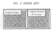
- Figure 3 shows an image that is halftone processed according to the conventional halftone processing method and an image that is obtained by printing the halftone processed image using the tri-level development method.
- the left image in Figure 3 is the halftone-processed image and the right image is the image in which the halftone-processed image is printed using the tri-level development method.
- patterns, which have not existed in the halftone-processed image are generated in the image printed using the tri-level development method. Thus, as can be seen, the image quality is greatly deteriorated.
- aspects of the present invention provide a method of processing halftone images using a tri-level development method, which can prevent deterioration of image quality.
- One exemplary embodiment of the present invention provides a printing method, which can prevent deterioration of the image quality.
- Another exemplary embodiment of the present invention provides a computer-readable medium for recording the halftone processing method.
- a method of processing halftone by generating a first dot pattern corresponding to a first colour and a second dot pattern corresponding to a second colour for a video signal having at least two colours comprises generating the first dot pattern by applying halftone processing to the video signal using a first screen, and generating the second dot pattern by applying halftone processing to the video signal using a second screen, the second screen being a complement of the first screen.
- the size of the first and second screens are the same as m ⁇ n, and the threshold values of corresponding positions between the first and second screens are complements of each other, each comprising a representative level.
- a method of printing a video signal having at least two colours.
- the method comprises generating a first dot pattern by applying halftone processing to the video signal using a first screen, generating a second dot pattern by applying halftone processing to the video signal using a second screen, the second screen being a complement of the first screen, and printing the first and second dot patterns using a tri-level development method.
- a computer-readable medium having stored thereon instructions comprising a program for causing a computer to perform a method of processing halftone by generating a first dot pattern corresponding to a first colour and a second dot pattern corresponding to a second colour for a video signal having at least two colours.
- the instructions comprise generating the first dot pattern by applying halftone processing to the video signal using a first screen, and generating the second dot pattern by applying halftone processing to the video signal using a second screen, the second screen being a complement of the first screen.
- an image forming apparatus configured to process halftone images for a video signal having at least two colours.
- the image forming apparatus comprises an interface for coupling signals to the image forming apparatus, and a control portion for conducting communications via the interface and controlling the image forming apparatus.
- the image forming apparatus further comprising a memory for storing information comprising print data and setting commands, an I/O interface, an operation panel for inputting various commands and data, the operation panel being coupled to the control portion through the I/O interface; and a print engine responsive to commands from the control portion, being coupled thereto via the I/O interface.
- the image forming apparatus being configured to generate a first dot pattern by applying halftone processing to the video signal using a first screen, the first dot pattern corresponding to a first colour, and generate a second dot pattern by applying halftone processing to the video signal using a second screen, the second dot pattern corresponding to a second colour, the first and second screens having a complementary relationship.
- a method of printing an image comprising generating a halftone image from a video signal in which the halftone image contains first and second colour information representing first and second colours in which the first and second colour information does not overlap, and printing the image by applying a tri-development printing method to the generated halftone image.
- FIG 4 is a flow chart for explaining a printing method according to an exemplary embodiment of the present invention.
- a video signal is input (S402).
- the video signal can comprise information concerning two colours, for example, Y and K or C and M.
- the video signal input to the printer can comprise information concerning all four colours.
- the video signal includes two colours for the convenience of explanation. This assumption is useful because the two colours are developed through the same development system.
- the video signal is halftone processed using a first screen (not shown) to obtain a dot pattern of the first colour (S404). Since the halftone processing of video signal or pixel information is well known to those of ordinary skill in the art, a detailed description thereof will be omitted.
- a dot pattern of a second colour is obtained by halftone processing the video signal using a second screen (not shown) (S406).
- the first screen and the second screen have a complementary relationship. That is, the second screen is obtained by taking a complement of the first screen. For example, in a colour system having eight levels, 0-7, 0 is the complement of 8, 1 is the complement of 7, 2 is the complement of 6, 3 is the complement of 5, and 4 is its own complement, and vice versa.
- the first dot pattern and the second dot pattern are then developed using a tri-level development method to print an image comprising two colours (S408).
- Figure 5 shows the first and second screens in the halftone processing method of Figure 4.
- a first screen 52 and a second screen 54 have the same size of 3x3 and the numbers at corresponding positions in the first and second screens 52 and 54 are in a complementary relationship of a representative level.
- the representative level signifies a resolution of a colour.
- a colour is represented by eight levels signified by the number range 0-7.
- the numbers at the upper left corners of the first and second screens 52 and 54 are "0" and "8" which satisfy the relationship of being complements of eight.
- the numbers "1" and "7" at the top center positions of the first and second screens 52 and 54 satisfy the complementary relationship.
- the first screen 52 and the second screen 54 have a complementary relationship
- the first dot pattern and the second dot pattern generated by the halftone processing have a complementary relationship as well.
- the generation of overlapped dots by the halftone processing is fundamentally prevented and the quality of a printed image is improved compared to the conventional tri-level development method.
- a yellow screen is made by applying a complementary relationship relative to a black screen.
- a magenta screen is made by applying a complementary relationship relative to a cyan screen. Then, dot patterns are produced in which the overlap of dots between yellow and black, and magenta and cyan, is reduced because of the characteristics of the screens having a complementary relationship.
- dot patterns with the reduced dot overlap are output in the tri-level development method, the loss of information due to the tri-level development method is reduced.
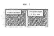
- Figure 6 shows an image that is halftone processed using the screen according to an exemplary embodiment of the present invention and an image that is obtained by printing the halftone processed image in the tri-level development method.
- the left image is one that is halftone processed according to an exemplary embodiment of the present invention and the right image is one obtained by printing the halftone processed image in the tri-level development method.
- the halftone processed image is printed in the tri-level development method, not only an undesired pattern is not generated compared to the case in which the image that is halftone processed according to conventional technology is printed in the tri-level development method, but also the generation of the unnecessary information is reduced, so that the quality of an image is greatly improved.
- the colour of a blue sky is a bright blue represented by a small number of cyan dots and a small number of magenta dots.
- a cyan colour and a magenta colour cannot be printed by being overlapped upon each other.
- a cyan colour and a magenta colour are overlapped to produce a blue colour.
- the colours are overlapped to represent a certain colour, a great deal information loss is made during the tri-level development.
- a dot pattern is produced by using the screens having a complementary relationship, the generation of a blue colour produced as a cyan colour and a magenta colour via overlapping is reduced so that information loss during the tri-level development is reduced.
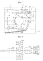
- FIG. 7 is a view showing the physical construction of a tri-level development type laser printer employing the halftone processing method according to an exemplary embodiment of the present invention.
- the laser printer comprises a print unit 100, a paper output path 310, a paper reverse path 320, a paper feed cassette 200, a pickup roller 201 for advancing paper from the stack 'S,' and a feed roller 210.
- the print unit 100 includes a charger 120, a light scanning unit (LSU) 130, a photosensitive drum 110, a developing portion 140 containing developer, a transfer belt 150, a transfer roller 160, and a fixer 170, and print an image on a print paper in an electrophotographic method.
- the developing portion 140 comprises a first developing unit 140a for black (K) and yellow (Y) and a second developing unit 140b for magenta (M) and cyan (C).
- the charger 120 supplies electrostatic charge to the photosensitive drum 100 so that the surface of the photosensitive drum 100 is charged to a uniform electrostatic potential.
- the LSU 130 scans light corresponding to a yellow dot pattern and a black dot pattern, for example, onto the photosensitive drum 110.
- a yellow electrostatic latent image and a black electrostatic latent image are formed due to a relative difference in the electric potential between a portion that is scanned by the light and a portion that is not scanned by the light.
- the yellow electrostatic latent image is charged positively while the black electrostatic latent image is charged negatively.
- the first developing unit 140a supplies the developer to these yellow and black electrostatic latent images to form yellow and black toner images. These yellow and black toner images are transferred to the transfer belt 150. When the yellow and black toner images are completely transferred to the transfer belt 150, magenta and cyan toner images are formed by the second developing unit 140b using the above method and transferred to the transfer belt 150 to be overlapped with each other. Thus, a complete colour toner image is formed on the transfer belt 150. The colour toner image is transferred to the print paper passing between the transfer belt 150 and the transfer roller 160.
- the fixer 170 applies heat and pressure to the colour toner image so that a complete colour image is obtained.
- the fixer 170 includes a heat roller 171 and a pressure roller 172.
- the paper output path 310 connects an outlet 102 of the print unit 100 and an output device and forms a path along which a printed-paper is output toward an output tray 230.
- the outlet 102 of the print unit 100 is located at an output side of the fixer 170.
- a pair of output rollers 220 rotating by being engaged with each other is used as the output device.
- the paper reverse path 320 is a path along which the print paper with an image printed on one side thereof is reversed and routed back to the print unit 100 so that an image can be printed on the rear surface of the print paper.
- the paper reverse path 320 branches from the paper output path 310 and extends to the feed roller 210 that supplies print paper to the print unit 100.
- Figure 8 is a block diagram of the construction of the printer of Figure 7.
- the printer includes an interface 202, a control portion 204, a memory 206, a lookup table 208, an I/O interface 210, an operation panel 212, and a print engine 214.
- the operation panel 212 includes a plurality of keys for inputting various commands by a user and a display device for displaying information on the operation of the printer for the user.
- the interface 202 couples a signal output from an external host computer (not shown), for example, various commands and data to be printed (hereinafter, referred to as the print data) and a signal output to the host computer, for example, a print state signal.
- the print data provided from the host computer is buffered in the memory 206.
- the control portion 204 communicates with the host computer through the interface 202 and controls the print engine 214 according to the print data and the various commands output from the host computer and the operation panel 212.
- the control portion 204 functions as a graphic display interface to perform the halftone processing for generating dot patterns from an input video signal.
- the control portion 204 comprises a microprocessor.
- the memory 206 stores setting information set through the operation panel 212 under the control of the control portion 204 and the print data output from the host computer.
- the memory 206 can store an execution program of the control portion 204, in particular, the halftone processing method, as shown in Figure 4.
- the I/O (input/output) interface 210 is connected between the control portion 204 and the operation panel 212 and the print engine 214 and provides an interface for I/O signals to the control portion 204.
- the print data is transmitted to the print engine 214 through the I/O interface 210.
- the print engine 214 for hard copying the print data comprises various mechanical parts for transfer and print of the print paper and performs printing under the control of the control portion 204.
- the first dot pattern and the second dot pattern, generated from the video signal having two colours are prevented from being overlapped with each other.
- the loss of colour information or the generation of empty information is prevented so that the quality of an image is improved.
Landscapes
- Engineering & Computer Science (AREA)
- Multimedia (AREA)
- Signal Processing (AREA)
- Physics & Mathematics (AREA)
- General Physics & Mathematics (AREA)
- Facsimile Image Signal Circuits (AREA)
- Color, Gradation (AREA)
- Image Processing (AREA)
Applications Claiming Priority (1)
| Application Number | Priority Date | Filing Date | Title |
|---|---|---|---|
| KR1020050044501A KR100727936B1 (ko) | 2005-05-26 | 2005-05-26 | 3레벨 현상 방법을 채용한 프린터의 하프톤 처리 방법, 이에 적합한 프린팅 방법, 그리고 이에 적합한 프로그램을 기록한 것을 특징으로 하는 컴퓨터로 읽을 수 있는 기록 매체 |
Publications (1)
| Publication Number | Publication Date |
|---|---|
| EP1727353A1 true EP1727353A1 (fr) | 2006-11-29 |
Family
ID=36975241
Family Applications (1)
| Application Number | Title | Priority Date | Filing Date |
|---|---|---|---|
| EP06114530A Withdrawn EP1727353A1 (fr) | 2005-05-26 | 2006-05-24 | Procédé et appareil d'impression |
Country Status (4)
| Country | Link |
|---|---|
| US (1) | US20060268343A1 (fr) |
| EP (1) | EP1727353A1 (fr) |
| KR (1) | KR100727936B1 (fr) |
| CN (1) | CN1869825A (fr) |
Cited By (1)
| Publication number | Priority date | Publication date | Assignee | Title |
|---|---|---|---|---|
| ES2350437A1 (es) * | 2010-06-29 | 2011-01-24 | Pemsa Pequeño Material Electrico, S.A. | Pieza de union entre bandejas portacables de chapa y bandejas portacables de rejilla. |
Families Citing this family (2)
| Publication number | Priority date | Publication date | Assignee | Title |
|---|---|---|---|---|
| CN101286002B (zh) * | 2007-04-11 | 2011-04-13 | 致伸科技股份有限公司 | 产生用于生成网屏掩膜的基本样板的方法 |
| KR101219434B1 (ko) * | 2008-04-24 | 2013-01-11 | 삼성전자주식회사 | 화상처리장치 및 화상처리방법 |
Citations (4)
| Publication number | Priority date | Publication date | Assignee | Title |
|---|---|---|---|---|
| US6203953B1 (en) * | 1999-11-10 | 2001-03-20 | Xerox Corporation | Method for forming a toner image with low toner pile height |
| US6373594B1 (en) * | 1998-12-29 | 2002-04-16 | Xerox Corporation | Color printer halftoning method and apparatus |
| US6426802B1 (en) * | 1999-01-19 | 2002-07-30 | Xerox Corporation | Complementary halftone screens for highlight printing |
| US20040150846A1 (en) * | 2003-02-05 | 2004-08-05 | Samsung Electronics Co., Ltd. | Color image halftoning apparatus and method, and mask generation apparatus and method used therein |
Family Cites Families (6)
| Publication number | Priority date | Publication date | Assignee | Title |
|---|---|---|---|---|
| US5557393A (en) * | 1994-11-04 | 1996-09-17 | Xerox Corporation | Process and apparatus for achieving customer selectable colors in an electrostatographic imaging system |
| JP3294502B2 (ja) * | 1996-07-24 | 2002-06-24 | 株式会社日立製作所 | 電子写真装置の露光量制御方法 |
| JPH1063063A (ja) * | 1996-08-23 | 1998-03-06 | Hitachi Ltd | 多色像形成装置 |
| US6307645B1 (en) * | 1998-12-22 | 2001-10-23 | Xerox Corporation | Halftoning for hi-fi color inks |
| JP3981217B2 (ja) * | 1999-04-15 | 2007-09-26 | リコープリンティングシステムズ株式会社 | 電子写真装置 |
| JP3566159B2 (ja) * | 1999-12-08 | 2004-09-15 | シャープ株式会社 | 機能表示方法 |
-
2005
- 2005-05-26 KR KR1020050044501A patent/KR100727936B1/ko not_active Expired - Fee Related
-
2006
- 2006-05-12 US US11/432,433 patent/US20060268343A1/en not_active Abandoned
- 2006-05-24 EP EP06114530A patent/EP1727353A1/fr not_active Withdrawn
- 2006-05-26 CN CNA2006100878793A patent/CN1869825A/zh active Pending
Patent Citations (4)
| Publication number | Priority date | Publication date | Assignee | Title |
|---|---|---|---|---|
| US6373594B1 (en) * | 1998-12-29 | 2002-04-16 | Xerox Corporation | Color printer halftoning method and apparatus |
| US6426802B1 (en) * | 1999-01-19 | 2002-07-30 | Xerox Corporation | Complementary halftone screens for highlight printing |
| US6203953B1 (en) * | 1999-11-10 | 2001-03-20 | Xerox Corporation | Method for forming a toner image with low toner pile height |
| US20040150846A1 (en) * | 2003-02-05 | 2004-08-05 | Samsung Electronics Co., Ltd. | Color image halftoning apparatus and method, and mask generation apparatus and method used therein |
Cited By (1)
| Publication number | Priority date | Publication date | Assignee | Title |
|---|---|---|---|---|
| ES2350437A1 (es) * | 2010-06-29 | 2011-01-24 | Pemsa Pequeño Material Electrico, S.A. | Pieza de union entre bandejas portacables de chapa y bandejas portacables de rejilla. |
Also Published As
| Publication number | Publication date |
|---|---|
| CN1869825A (zh) | 2006-11-29 |
| US20060268343A1 (en) | 2006-11-30 |
| KR20060124894A (ko) | 2006-12-06 |
| KR100727936B1 (ko) | 2007-06-13 |
Similar Documents
| Publication | Publication Date | Title |
|---|---|---|
| US6993269B2 (en) | Image forming apparatus, image processing apparatus, image forming method and image processing method for forming/processing a three-dimensional image | |
| US7973988B2 (en) | Color image forming apparatus and control method thereof | |
| US8174551B2 (en) | Image forming apparatus and image forming method which utilizes a trapping process | |
| JP5595350B2 (ja) | 画像処理装置および画像形成装置 | |
| EP1727353A1 (fr) | Procédé et appareil d'impression | |
| JP4237165B2 (ja) | 画像処理装置及び画像形成装置 | |
| JP7484589B2 (ja) | 情報処理装置、方法、プログラムおよび印刷システム | |
| US8345312B2 (en) | Method of printing a text with an apparatus using channels | |
| JP2007136775A (ja) | 露光画像入力装置及びプリンタ装置 | |
| US6271930B1 (en) | Image processing apparatus and method, and storage medium | |
| JP3496428B2 (ja) | 複写機 | |
| JP2006195246A (ja) | 画像形成装置 | |
| JP3345448B2 (ja) | カラー画像形成装置 | |
| JP2021187083A (ja) | 画像形成装置、および画像形成方法 | |
| JP4355541B2 (ja) | 出力カウント方法、画像形成装置およびプログラム | |
| US7817308B2 (en) | Image forming apparatus, control method for image forming apparatus and storage medium storing control program | |
| JPH10186768A (ja) | 画像形成装置 | |
| JPH09265223A (ja) | 画像形成装置 | |
| JP4085890B2 (ja) | 画像形成装置 | |
| JP2000029257A (ja) | 画像処理装置及び方法 | |
| JP2003312081A (ja) | 印刷システム、印刷システムのコントローラ、印刷方法、および記憶媒体並びにプログラム | |
| JPH0784077B2 (ja) | デジタルカラ−記録装置 | |
| JP2021069043A (ja) | 画像形成装置、画像形成方法及びプログラム | |
| JP5794042B2 (ja) | 色材量削減方法、および画像処理装置 | |
| JP2006157424A (ja) | 画像処理装置、及び画像処理方法 |
Legal Events
| Date | Code | Title | Description |
|---|---|---|---|
| PUAI | Public reference made under article 153(3) epc to a published international application that has entered the european phase |
Free format text: ORIGINAL CODE: 0009012 |
|
| AK | Designated contracting states |
Kind code of ref document: A1 Designated state(s): AT BE BG CH CY CZ DE DK EE ES FI FR GB GR HU IE IS IT LI LT LU LV MC NL PL PT RO SE SI SK TR |
|
| AX | Request for extension of the european patent |
Extension state: AL BA HR MK YU |
|
| 17P | Request for examination filed |
Effective date: 20070508 |
|
| AKX | Designation fees paid |
Designated state(s): DE FR GB IT NL |
|
| 17Q | First examination report despatched |
Effective date: 20070704 |
|
| STAA | Information on the status of an ep patent application or granted ep patent |
Free format text: STATUS: THE APPLICATION IS DEEMED TO BE WITHDRAWN |
|
| 18D | Application deemed to be withdrawn |
Effective date: 20080115 |