EP1728032B1 - Paroi thermo-isolante - Google Patents
Paroi thermo-isolante Download PDFInfo
- Publication number
- EP1728032B1 EP1728032B1 EP05717013A EP05717013A EP1728032B1 EP 1728032 B1 EP1728032 B1 EP 1728032B1 EP 05717013 A EP05717013 A EP 05717013A EP 05717013 A EP05717013 A EP 05717013A EP 1728032 B1 EP1728032 B1 EP 1728032B1
- Authority
- EP
- European Patent Office
- Prior art keywords
- skin
- backing part
- thermally insulating
- insulating wall
- wall according
- Prior art date
- Legal status (The legal status is an assumption and is not a legal conclusion. Google has not performed a legal analysis and makes no representation as to the accuracy of the status listed.)
- Expired - Lifetime
Links
Images


Classifications
-
- F—MECHANICAL ENGINEERING; LIGHTING; HEATING; WEAPONS; BLASTING
- F25—REFRIGERATION OR COOLING; COMBINED HEATING AND REFRIGERATION SYSTEMS; HEAT PUMP SYSTEMS; MANUFACTURE OR STORAGE OF ICE; LIQUEFACTION SOLIDIFICATION OF GASES
- F25D—REFRIGERATORS; COLD ROOMS; ICE-BOXES; COOLING OR FREEZING APPARATUS NOT OTHERWISE PROVIDED FOR
- F25D23/00—General constructional features
- F25D23/06—Walls
- F25D23/065—Details
- F25D23/067—Supporting elements
-
- E—FIXED CONSTRUCTIONS
- E05—LOCKS; KEYS; WINDOW OR DOOR FITTINGS; SAFES
- E05B—LOCKS; ACCESSORIES THEREFOR; HANDCUFFS
- E05B1/00—Knobs or handles for wings; Knobs, handles, or press buttons for locks or latches on wings
Definitions
- the present invention relates to a heat-insulating wall, in particular a wall, which is part of a door or a housing of a refrigerator.
- Such walls conventionally comprise a low strength insulation layer bounded by at least one solid skin.
- a handle on a refrigerator door or refrigerated goods in the body of the refrigerator this often happens with anchored in an opening of the skin backing parts that introduce a force exerted by the mounted part locally distributed in the skin , so that it is able to carry the power despite a low material thickness.
- a heat-insulating wall according to the preamble of claim 1 is made EP 1 032 795 B1 known.
- the backing member is fastened in the manner of a bayonet coupling to the outer skin of a refrigerator door, by insertion into the opening from a first side of the skin and turning about the insertion direction into a locked position, in which a contact surface of a retaining wing of the backing part at a second
- a second abutment surface of the backing portion abuts the first side of the solid skin so as to immobilize the backing member in the insertion direction
- a stop flank of the backing member abuts a radially oriented edge of the opening with respect to the insertion direction
- the distance between the two contact surfaces must be exactly adapted to the thickness of the solid skin. If the distance is too large, the backing part finds no firm grip; if it is too small, it is impossible to turn the backing part into the locked position.
- Object of the present invention is to develop this known heat-insulating wall so that a higher tolerance in terms of variations in the thickness of the skin or the distance of the two contact surfaces is achieved.
- a flexibility of the retaining wing in the insertion direction is achieved in that between the retaining wing and the stop edge, a material taper is provided. Due to the weakening of the material thickness between the holding wing and the stop flank, elastic behavior is achieved for the holding wing to a certain extent. If the backing is to be mounted on a solid skin whose thickness is slightly greater than the distance between the two contact surfaces, the retaining wing in the insertion slightly yield, and the backing member can be brought into the locked position and remains stable in this.
- the elastic behavior of the holding wing is particularly simple to determine by application of the material taper as a gap or slit.
- the first side of the skin preferably faces the insulation layer, so that the backing part is essentially embedded in the insulation layer on the finished wall.
- the backing part is preferably immobilized in the insulating foam in the locked position.
- a sealing lip of the backing piece extending around the opening and resting against the first side of the skin can serve to prevent the material of the insulating layer from entering the opening.
- This sealing lip can simultaneously serve as the second bearing surface of the backing part.
- the backing part is separated from the insulating layer by a cup placed over the backing piece, an edge of which rests against the first side of the skin.
- this edge may again preferably be in the form of a conical sealing lip.
- the cup does not have to bear the weight of an element engaging the backing part, but essentially serves only to shield the opening of the insulation layer, it may advantageously be formed of a more flexible material than the backing part. This flexibility favors effective sealing against the insulating layer between the solid skin and the rim of the cup.
- the cup is provided with wings for immobilizing the backing part in the insulating layer.
- the backing piece and the cup are preferably non-rotatably locked to one another, preferably in that of the backing piece and the cup, one has at least one groove oriented in the insertion direction and the other has a rib that is complementary to the groove.
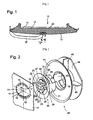
- Figure 1 shows a refrigeration appliance door as an example of a heat-insulating wall according to the invention, with a door handle attached to the door by means of a Schulegteils.
- FIG. 2 is an exploded perspective view of the backing member and a cup separating the backing member from the insulating layer;
- Fig. 3 is an enlarged view of the backing part
- Fig. 4 is a perspective view of the backing part and the cup in the nested state.
- Fig. 1 shows a refrigerator door 10, which by a non-cutting shaping of a Plastic board produced inner lining 11, a heat insulating layer 12 and connected to the inner lining 11 to a door body, serving as the outer skin 13 has outer lining, which by the wetting effect of the polyurethane foam formed in the space defined by the inner lining 11 and the outer skin 13 space insulation 12 is connected to the inner lining 11 to a dimensionally stable structure.
- door handle On the outer skin 13 a bow-like trained, explained in more detail below door handle is fixed to two mounting positions I and II, of which the mounting position 1 is provided to the installation position of the refrigerator door 10 vertically extending side cheeks of the outer skin 13, while the mounting position II in about the middle Width of the door 10 is provided at the front side formed by the outer skin 13.
- the outer skin 13 which is made of sheet steel, is provided with a substantially circular opening 14, in the opening area of which at least two approximately oppositely disposed projections project integrally with integrally formed projections 15, which are stepped in direction towards the heat insulation layer 12 are offset by tapping off.
- a backing member 20 provided therein for insertion into the opening 14 and latching in the manner of a bayonet catch is integrally formed substantially by a hollow cylindrical shaft 21, a base plate 22 substantially closing the shaft 21 at one end, and a frusto-conical sealing lip extending around the shaft 21 23 formed.
- a cross-shaped opening 24 in the base plate 22 is provided for anchoring the door handle therein. Above and below the cross-shaped opening 24 are from the base plate 22 in the axial direction two circular-arc-shaped ribs 25 from. Of the ribs 25 are in turn two spaced from the plate 22 to form a groove 26 retaining wings 27 and two each a radial recess 28 delimiting locking lugs 29, 30 from.
- the backing part 20 is provided to be inserted into the opening 14 of the outer wall 13 from its inside in a rotational orientation in which the retaining wings 27 and locking lugs 29 of a rib 25 each in a cutout 17 between one of the projections 15 and a fixing and retaining lug 16 engage. If after this insertion, the inside of the projection 15 abuts against the base plate 22 of the backing part 10, the latter is rotatable in the opening 14 in an orientation in which one of the base plate 22 facing abutment surface of each retaining wing 27 abuts an outer side of the projection 15.
- the locating and retaining tabs 16 must each engage one of the recesses 28 of the backing member, i. the backing part 20 has to be turned so far that the fixing and retaining lugs 16 respectively pass the latching lug 29 which lies between the retaining wing 27 and the radial recess 28.
- the freedom of rotation of the backing part 20 is limited by the fact that a radially oriented flank 34 (see FIG. 3) facing the retaining wing 27 abuts against the latching lug 29 against a radially oriented edge 18 of the projection 15.
- a formed between this edge 34 and the retaining wing 27 radial slot 31 increases the elastic deformability of the holding wing 27 when the backing member 20 is turned onto an outer skin 13 whose wall thickness is slightly greater than the width of the groove between the retaining wing 27 and the base plate 22nd , and while the fixing and retaining lug 16, the recess 28, the locking lug 29 passes just before the engagement.
- EP 1 032 795 B1 is also ensured by the presence of the slot 31 that the torque required to unscrew the backing part on the outer wall does not increase the closer the radial edge 17 of the flank 34 comes.
- the outer edge of the conical sealing lip 23 presses elastically against the inside of the outer skin 13 over its entire circumference. If the material of the sealing lip 23 were sufficiently supple, this sealing lip 23 could already be provide adequate protection against the passage of foam from the gap to the interior of the backing member 20 (and thus possibly to the outside of the door). However, in order to provide a robust anchorage to the door handle, the material of the backing member 20 must be quite stiff, so that complete foam tightness of the sealing lip 23 is difficult to guarantee.
- cup 40 which is made of a more flexible material than that of the backing piece 20 and is intended to be slipped over the backing sheet 20 attached to the skin 13, the cup 40 facing one of the base sheet 22 open rear side of the shaft 21 of the backing member 20 closes and at the same time forms an effective foam seal on the inside of the outer skin 13 by means of a conical sealing lip 41, which surrounds the sealing lip 23 of the backing member 20 outside.
- the shaft 21 of the backing part 20 is provided with a peripheral rib 32 (FIG. 3), to which a complementary circumferential groove 42 is formed on the inside of the cup 40.
- Cup 40 and backing member 20 are also rotatable with Assistance provided by two diametrically opposed ribs 33 of the shaft 21 and grooves 43 of the cup 40 extending in the direction of attachment.
- the cup 40 is at the level of its bottom with a transversely aligned to the mounting direction flange 44 and a plurality of with respect to the axis of the cup 40 radially and parallel to Aufsteckraum extending wings 45th Mistake.
- the cruciform opening 24 of the backing member 20 fixedly mounted in the skin 13 is intended to insert into the vertical slot of the aperture 24 an approximately T-shaped armature of the door handle and subsequently to engage the shank of the anchor in one of the two horizontal slots extending from the vertical slot Branches of the opening 24 to move, wherein the shaft held by the transverse bar of the armature above and below the branch behind the base plate 22 of the backing member 20 engages.
- the anchor In which of the two branches of the opening 24 of the backing 20 placed centrally in the outer skin 13 the anchor is displaced, depends on the two side cheeks of the outer skin 13, the other end of the door handle is fixed to the position I.
- the cross-shaped opening 24 in the base plate 22 of the backing member 20 can be replaced by any other suitable for fastening the respective desired part shapes.
- a backing member 20 of the type described above may also be used to be mounted in an opening of the inner liner 11 so as to attach to this backing member 20 refrigerated goods carriers of the interior of the refrigerator or telescopic rails on which such refrigerated goods carrier is slidable.
Landscapes
- Engineering & Computer Science (AREA)
- Chemical & Material Sciences (AREA)
- Combustion & Propulsion (AREA)
- Physics & Mathematics (AREA)
- Mechanical Engineering (AREA)
- Thermal Sciences (AREA)
- General Engineering & Computer Science (AREA)
- Refrigerator Housings (AREA)
- Building Environments (AREA)
- Glass Compositions (AREA)
- Table Devices Or Equipment (AREA)
- Cold Cathode And The Manufacture (AREA)
Claims (14)
- Paroi calorifuge avec au moins une membrane résistante (13) délimitant une couche d'isolation (12) et une partie intermédiaire (20) ancrée dans une ouverture (14) de la membrane (13) qui, dans une première position de rotation d'un premier côté de la membrane résistante (13), est introduite dans l'ouverture (14) et est amenée, par rotation par rapport au sens d'introduction, dans une position bloquée, dans laquelle une surface d'appui d'une aile de maintien (27) de la pièce intermédiaire (20) est adjacente au deuxième côté de la membrane résistante (13), une deuxième surface d'appui (22) de la pièce intermédiaire (20) est adjacente au premier côté de la membrane résistante (13) et un flanc de butée (34) de la pièce intermédiaire (20) bute sur une arête (18), orientée radialement, de l'ouverture (14), caractérisée en ce que entre l'aile de maintien (27) et le flanc de butée (34) est prévu un rétrécissement de la matière disposé transversalement au sens de rotation.
- Paroi calorifuge selon la revendication 1, caractérisée en ce que le rétrécissement de la matière est conçu en étant ouvert vers le bord vers le bord libre de l'aile de maintien (27) et guidé radialement vers l'intérieur.
- Paroi calorifuge selon la revendication 1 ou 2, caractérisée en ce que le rétrécissement de la matière est conçu comme une fente pénétrant l'épaisseur de la matière de l'aile de maintien (27), sur sa base de fente, un listel de liaison est conçu entre l'étrier de maintien (27) et le flanc de butée (34).
- Paroi calorifuge selon la revendication 1, caractérisée en ce que le premier côté de la membrane (13) est orienté vers la couche d'isolation (12).
- Paroi calorifuge selon la revendication 1 ou 4, caractérisée en ce que la couche d'isolation (12) est formée par remplissage d'un espace intermédiaire avec une mousse d'isolation et la partie intermédiaire (20) est immobilisée dans la mousse d'isolation dans la position bloquée.
- Paroi calorifuge selon l'une des revendications précédentes, caractérisée en ce que la pièce intermédiaire (20) porte une lèvre d'étanchéité (23, 41) s'étendant autour de l'ouverture (14), adjacente au premier côté de la membrane (13).
- Paroi calorifuge selon l'une des revendications précédentes, caractérisée en ce que la pièce intermédiaire (20) est séparée de la couche d'isolation (12) par un godet (40) enfoncé sur la pièce intermédiaire (20), dont un bord (41) est adjacent au premier côté de la membrane (13).
- Paroi calorifuge selon la revendication 7, caractérisée en ce que le bord du godet (40) est formé par une lèvre d'étanchéité conique (41).
- Paroi calorifuge selon la revendication 7 ou 8, caractérisée en ce que le godet (40) est formé d'une matière plus souple que la pièce intermédiaire (20).
- Paroi calorifuge selon la revendication 7, 8 ou 9, caractérisée en ce que le godet (40) est doté d'ailes (45) faisant saillie dans la couche d'isolation (12).
- Paroi calorifuge selon l'une des revendications 7 à 10, caractérisée en ce que la pièce intermédiaire (20) et le godet (40) sont enclenchés l'un contre l'autre en rotation.
- Paroi calorifuge selon la revendication 11, caractérisée en ce que de la pièce intermédiaire (20) et du godet (40), l'un présente au moins une rainure (43) orientée dans le sens de guidage et l'autre présente une nervure (33) respectivement complémentaire à la rainure (43).
- Paroi calorifuge pour un appareil frigorifique selon l'une des revendications précédentes, caractérisée en ce que la membrane (13) est une paroi extérieure d'une porte (10) de l'appareil frigorifique et en ce que une poignée est ancrée sur la pièce intermédiaire (20).
- Paroi calorifuge pour un appareil frigorifique selon l'une des revendications 1 à 10, caractérisée en ce que la membrane (13) est un bac interne (11) de l'appareil frigorifique et en ce que sur la partie intermédiaire (20) est ancré un support de produits réfrigérés.
Applications Claiming Priority (2)
| Application Number | Priority Date | Filing Date | Title |
|---|---|---|---|
| DE102004012539A DE102004012539A1 (de) | 2004-03-15 | 2004-03-15 | Wärmeisolierende Wand |
| PCT/EP2005/051121 WO2005090879A2 (fr) | 2004-03-15 | 2005-03-11 | Paroi thermo-isolante |
Publications (2)
| Publication Number | Publication Date |
|---|---|
| EP1728032A2 EP1728032A2 (fr) | 2006-12-06 |
| EP1728032B1 true EP1728032B1 (fr) | 2007-09-12 |
Family
ID=34962093
Family Applications (1)
| Application Number | Title | Priority Date | Filing Date |
|---|---|---|---|
| EP05717013A Expired - Lifetime EP1728032B1 (fr) | 2004-03-15 | 2005-03-11 | Paroi thermo-isolante |
Country Status (8)
| Country | Link |
|---|---|
| EP (1) | EP1728032B1 (fr) |
| CN (1) | CN100472157C (fr) |
| AT (1) | ATE373215T1 (fr) |
| BR (1) | BRPI0508268A (fr) |
| DE (2) | DE102004012539A1 (fr) |
| ES (1) | ES2293548T3 (fr) |
| RU (1) | RU2377480C2 (fr) |
| WO (1) | WO2005090879A2 (fr) |
Families Citing this family (5)
| Publication number | Priority date | Publication date | Assignee | Title |
|---|---|---|---|---|
| KR100776271B1 (ko) * | 2007-01-26 | 2007-11-15 | 삼성광주전자 주식회사 | 냉장고 |
| DE102009002444A1 (de) * | 2009-04-16 | 2010-10-21 | BSH Bosch und Siemens Hausgeräte GmbH | Kältegerät |
| WO2014102372A1 (fr) * | 2012-12-31 | 2014-07-03 | Arcelik Anonim Sirketi | Réfrigérateur comprenant une poignée de porte |
| DE102015221431A1 (de) * | 2015-11-02 | 2017-05-04 | BSH Hausgeräte GmbH | Kältegerät mit Hinterlegteil und Verfahren zum Herstellen eines Kältegerätes mit Hinterlegteil |
| CN209637377U (zh) * | 2018-12-05 | 2019-11-15 | 福建西河卫浴科技有限公司 | 一种拉手组件和淋浴房 |
Family Cites Families (8)
| Publication number | Priority date | Publication date | Assignee | Title |
|---|---|---|---|---|
| DE1112265B (de) * | 1952-07-25 | 1961-08-03 | Saba Gmbh | Zur Auflage von Fachboeden in schrankartigen Behaeltern, insbesondere von Tragblechen und -rosten in Eis- und Kuehlschraenken, dienen der auswechselbarer Traeger |
| US3179367A (en) * | 1963-04-11 | 1965-04-20 | Illinois Tool Works | Plastic quarter turn shelf support |
| SU1423874A1 (ru) * | 1986-07-07 | 1988-09-15 | Предприятие П/Я М-5016 | Защелка двери холодильной камеры |
| DE19751310A1 (de) * | 1997-11-19 | 1999-05-20 | Bosch Siemens Hausgeraete | Kältegerät |
| KR100402599B1 (ko) * | 1999-08-27 | 2003-10-22 | 주식회사 엘지이아이 | 냉장고의 가스켓 체결구조 |
| AU781858B2 (en) * | 1999-12-28 | 2005-06-16 | Lg Electronics Inc. | Door handle installation structure of refrigerator |
| CN100427859C (zh) * | 2002-08-13 | 2008-10-22 | 乐金电子(天津)电器有限公司 | 电冰箱的把手安装装置 |
| CN2569055Y (zh) * | 2002-08-23 | 2003-08-27 | 苏州三星电子有限公司 | 电冰箱的门把手连接机构 |
-
2004
- 2004-03-15 DE DE102004012539A patent/DE102004012539A1/de not_active Withdrawn
-
2005
- 2005-03-11 DE DE502005001489T patent/DE502005001489D1/de not_active Expired - Lifetime
- 2005-03-11 ES ES05717013T patent/ES2293548T3/es not_active Expired - Lifetime
- 2005-03-11 WO PCT/EP2005/051121 patent/WO2005090879A2/fr not_active Ceased
- 2005-03-11 BR BRPI0508268-4A patent/BRPI0508268A/pt not_active IP Right Cessation
- 2005-03-11 RU RU2006130850/12A patent/RU2377480C2/ru not_active IP Right Cessation
- 2005-03-11 AT AT05717013T patent/ATE373215T1/de not_active IP Right Cessation
- 2005-03-11 CN CNB2005800083215A patent/CN100472157C/zh not_active Expired - Fee Related
- 2005-03-11 EP EP05717013A patent/EP1728032B1/fr not_active Expired - Lifetime
Also Published As
| Publication number | Publication date |
|---|---|
| BRPI0508268A (pt) | 2007-07-31 |
| WO2005090879A2 (fr) | 2005-09-29 |
| RU2006130850A (ru) | 2008-04-27 |
| ATE373215T1 (de) | 2007-09-15 |
| DE502005001489D1 (de) | 2007-10-25 |
| EP1728032A2 (fr) | 2006-12-06 |
| WO2005090879A3 (fr) | 2006-01-12 |
| DE102004012539A1 (de) | 2005-10-06 |
| RU2377480C2 (ru) | 2009-12-27 |
| CN100472157C (zh) | 2009-03-25 |
| ES2293548T3 (es) | 2008-03-16 |
| CN1934402A (zh) | 2007-03-21 |
Similar Documents
| Publication | Publication Date | Title |
|---|---|---|
| AT404858B (de) | Als scharniertopf ausgebildeter tür-anschlagteil für möbelscharniere | |
| DE60100608T2 (de) | Wasserdichte Halteöse | |
| EP0530348B1 (fr) | Tenon de retenue en plastique, notamment pour fournitures pour meubles | |
| LU86631A1 (de) | Einstellbare befestigungsvorrichtung zum zusammenfuegen von zwei bauteilen | |
| EP0750554B1 (fr) | Bras pour systeme d'essuie-glace destine en particulier aux vehicules automobiles | |
| WO1991011631A1 (fr) | Element de fixation autoforeur | |
| EP2206856B1 (fr) | Poignée d'actionnement | |
| DE102019126620A1 (de) | Befestigungsvorrichtung | |
| DE10300991A1 (de) | Ausgleichsverschraubung | |
| DE19755899C2 (de) | Antriebseinheit für Verstelleinrichtungen | |
| EP1728032B1 (fr) | Paroi thermo-isolante | |
| EP1103771B1 (fr) | Porte d'appareil frigorifique | |
| DE102010008040A1 (de) | Vorrichtung zur lösbaren Verbindung zweier Bauteile | |
| EP3714173A1 (fr) | Dispositif de fixation inamovible | |
| EP0754827B1 (fr) | Dispositif pour la fixation amovible et axialement non coulissante d'une poignée sur un élément de palier, notamment pour une poignée de porte ou fenêtre | |
| EP1048856B1 (fr) | Elément de fixation d'éléments d'isolation | |
| EP0898089A2 (fr) | Montage d'une seule pièce | |
| DE19805949A1 (de) | Befestigungselement für eine Fußmatte in einem Kraftwagen | |
| DE102011004315B4 (de) | Vorrichtung zum Einbau einer Geschirrspülmaschine in eine Einbaunische | |
| DE4414460C5 (de) | Als Scharniertopf ausgebildeter Tür-Anschlagteil für Möbelscharniere | |
| EP0942121B1 (fr) | Rosette pour ferrure de porte | |
| EP3363969B1 (fr) | Poignée d'actionnement | |
| DE19914189A1 (de) | Verbindungsvorrichtung | |
| EP0344424B1 (fr) | Attache verrouillante par rotation | |
| EP2019953A1 (fr) | Porte pour un espace intérieur séparable |
Legal Events
| Date | Code | Title | Description |
|---|---|---|---|
| PUAI | Public reference made under article 153(3) epc to a published international application that has entered the european phase |
Free format text: ORIGINAL CODE: 0009012 |
|
| 17P | Request for examination filed |
Effective date: 20061016 |
|
| AK | Designated contracting states |
Kind code of ref document: A2 Designated state(s): AT BE BG CH CY CZ DE DK EE ES FI FR GB GR HU IE IS IT LI LT LU MC NL PL PT RO SE SI SK TR |
|
| GRAP | Despatch of communication of intention to grant a patent |
Free format text: ORIGINAL CODE: EPIDOSNIGR1 |
|
| DAX | Request for extension of the european patent (deleted) | ||
| GRAS | Grant fee paid |
Free format text: ORIGINAL CODE: EPIDOSNIGR3 |
|
| GRAA | (expected) grant |
Free format text: ORIGINAL CODE: 0009210 |
|
| AK | Designated contracting states |
Kind code of ref document: B1 Designated state(s): AT BE BG CH CY CZ DE DK EE ES FI FR GB GR HU IE IS IT LI LT LU MC NL PL PT RO SE SI SK TR |
|
| REG | Reference to a national code |
Ref country code: GB Ref legal event code: FG4D Free format text: NOT ENGLISH |
|
| REG | Reference to a national code |
Ref country code: CH Ref legal event code: EP |
|
| GBT | Gb: translation of ep patent filed (gb section 77(6)(a)/1977) |
Effective date: 20070912 |
|
| REF | Corresponds to: |
Ref document number: 502005001489 Country of ref document: DE Date of ref document: 20071025 Kind code of ref document: P |
|
| REG | Reference to a national code |
Ref country code: IE Ref legal event code: FG4D Free format text: LANGUAGE OF EP DOCUMENT: GERMAN |
|
| REG | Reference to a national code |
Ref country code: SE Ref legal event code: TRGR |
|
| ET | Fr: translation filed | ||
| PG25 | Lapsed in a contracting state [announced via postgrant information from national office to epo] |
Ref country code: LT Free format text: LAPSE BECAUSE OF FAILURE TO SUBMIT A TRANSLATION OF THE DESCRIPTION OR TO PAY THE FEE WITHIN THE PRESCRIBED TIME-LIMIT Effective date: 20070912 Ref country code: FI Free format text: LAPSE BECAUSE OF FAILURE TO SUBMIT A TRANSLATION OF THE DESCRIPTION OR TO PAY THE FEE WITHIN THE PRESCRIBED TIME-LIMIT Effective date: 20070912 |
|
| PG25 | Lapsed in a contracting state [announced via postgrant information from national office to epo] |
Ref country code: PL Free format text: LAPSE BECAUSE OF FAILURE TO SUBMIT A TRANSLATION OF THE DESCRIPTION OR TO PAY THE FEE WITHIN THE PRESCRIBED TIME-LIMIT Effective date: 20070912 |
|
| NLV1 | Nl: lapsed or annulled due to failure to fulfill the requirements of art. 29p and 29m of the patents act | ||
| REG | Reference to a national code |
Ref country code: ES Ref legal event code: FG2A Ref document number: 2293548 Country of ref document: ES Kind code of ref document: T3 |
|
| PG25 | Lapsed in a contracting state [announced via postgrant information from national office to epo] |
Ref country code: GR Free format text: LAPSE BECAUSE OF FAILURE TO SUBMIT A TRANSLATION OF THE DESCRIPTION OR TO PAY THE FEE WITHIN THE PRESCRIBED TIME-LIMIT Effective date: 20071213 Ref country code: NL Free format text: LAPSE BECAUSE OF FAILURE TO SUBMIT A TRANSLATION OF THE DESCRIPTION OR TO PAY THE FEE WITHIN THE PRESCRIBED TIME-LIMIT Effective date: 20070912 |
|
| REG | Reference to a national code |
Ref country code: IE Ref legal event code: FD4D |
|
| PG25 | Lapsed in a contracting state [announced via postgrant information from national office to epo] |
Ref country code: CZ Free format text: LAPSE BECAUSE OF FAILURE TO SUBMIT A TRANSLATION OF THE DESCRIPTION OR TO PAY THE FEE WITHIN THE PRESCRIBED TIME-LIMIT Effective date: 20070912 Ref country code: IS Free format text: LAPSE BECAUSE OF FAILURE TO SUBMIT A TRANSLATION OF THE DESCRIPTION OR TO PAY THE FEE WITHIN THE PRESCRIBED TIME-LIMIT Effective date: 20080112 Ref country code: PT Free format text: LAPSE BECAUSE OF FAILURE TO SUBMIT A TRANSLATION OF THE DESCRIPTION OR TO PAY THE FEE WITHIN THE PRESCRIBED TIME-LIMIT Effective date: 20080212 Ref country code: SK Free format text: LAPSE BECAUSE OF FAILURE TO SUBMIT A TRANSLATION OF THE DESCRIPTION OR TO PAY THE FEE WITHIN THE PRESCRIBED TIME-LIMIT Effective date: 20070912 |
|
| PG25 | Lapsed in a contracting state [announced via postgrant information from national office to epo] |
Ref country code: RO Free format text: LAPSE BECAUSE OF FAILURE TO SUBMIT A TRANSLATION OF THE DESCRIPTION OR TO PAY THE FEE WITHIN THE PRESCRIBED TIME-LIMIT Effective date: 20070912 |
|
| PLBE | No opposition filed within time limit |
Free format text: ORIGINAL CODE: 0009261 |
|
| STAA | Information on the status of an ep patent application or granted ep patent |
Free format text: STATUS: NO OPPOSITION FILED WITHIN TIME LIMIT |
|
| PG25 | Lapsed in a contracting state [announced via postgrant information from national office to epo] |
Ref country code: DK Free format text: LAPSE BECAUSE OF FAILURE TO SUBMIT A TRANSLATION OF THE DESCRIPTION OR TO PAY THE FEE WITHIN THE PRESCRIBED TIME-LIMIT Effective date: 20070912 |
|
| 26N | No opposition filed |
Effective date: 20080613 |
|
| BERE | Be: lapsed |
Owner name: BSH BOSCH UND SIEMENS HAUSGERATE G.M.B.H. Effective date: 20080331 |
|
| PG25 | Lapsed in a contracting state [announced via postgrant information from national office to epo] |
Ref country code: IE Free format text: LAPSE BECAUSE OF FAILURE TO SUBMIT A TRANSLATION OF THE DESCRIPTION OR TO PAY THE FEE WITHIN THE PRESCRIBED TIME-LIMIT Effective date: 20070912 Ref country code: MC Free format text: LAPSE BECAUSE OF NON-PAYMENT OF DUE FEES Effective date: 20080331 |
|
| PG25 | Lapsed in a contracting state [announced via postgrant information from national office to epo] |
Ref country code: EE Free format text: LAPSE BECAUSE OF FAILURE TO SUBMIT A TRANSLATION OF THE DESCRIPTION OR TO PAY THE FEE WITHIN THE PRESCRIBED TIME-LIMIT Effective date: 20070912 |
|
| PG25 | Lapsed in a contracting state [announced via postgrant information from national office to epo] |
Ref country code: BE Free format text: LAPSE BECAUSE OF NON-PAYMENT OF DUE FEES Effective date: 20080331 |
|
| PG25 | Lapsed in a contracting state [announced via postgrant information from national office to epo] |
Ref country code: SI Free format text: LAPSE BECAUSE OF FAILURE TO SUBMIT A TRANSLATION OF THE DESCRIPTION OR TO PAY THE FEE WITHIN THE PRESCRIBED TIME-LIMIT Effective date: 20070912 |
|
| PG25 | Lapsed in a contracting state [announced via postgrant information from national office to epo] |
Ref country code: CY Free format text: LAPSE BECAUSE OF FAILURE TO SUBMIT A TRANSLATION OF THE DESCRIPTION OR TO PAY THE FEE WITHIN THE PRESCRIBED TIME-LIMIT Effective date: 20070912 |
|
| PG25 | Lapsed in a contracting state [announced via postgrant information from national office to epo] |
Ref country code: BG Free format text: LAPSE BECAUSE OF FAILURE TO SUBMIT A TRANSLATION OF THE DESCRIPTION OR TO PAY THE FEE WITHIN THE PRESCRIBED TIME-LIMIT Effective date: 20071212 Ref country code: AT Free format text: LAPSE BECAUSE OF NON-PAYMENT OF DUE FEES Effective date: 20080311 |
|
| REG | Reference to a national code |
Ref country code: CH Ref legal event code: PL |
|
| PG25 | Lapsed in a contracting state [announced via postgrant information from national office to epo] |
Ref country code: LI Free format text: LAPSE BECAUSE OF NON-PAYMENT OF DUE FEES Effective date: 20090331 Ref country code: CH Free format text: LAPSE BECAUSE OF NON-PAYMENT OF DUE FEES Effective date: 20090331 |
|
| PG25 | Lapsed in a contracting state [announced via postgrant information from national office to epo] |
Ref country code: LU Free format text: LAPSE BECAUSE OF NON-PAYMENT OF DUE FEES Effective date: 20080311 Ref country code: HU Free format text: LAPSE BECAUSE OF FAILURE TO SUBMIT A TRANSLATION OF THE DESCRIPTION OR TO PAY THE FEE WITHIN THE PRESCRIBED TIME-LIMIT Effective date: 20080313 |
|
| PGFP | Annual fee paid to national office [announced via postgrant information from national office to epo] |
Ref country code: SE Payment date: 20120322 Year of fee payment: 8 |
|
| REG | Reference to a national code |
Ref country code: SE Ref legal event code: EUG |
|
| PG25 | Lapsed in a contracting state [announced via postgrant information from national office to epo] |
Ref country code: SE Free format text: LAPSE BECAUSE OF NON-PAYMENT OF DUE FEES Effective date: 20130312 |
|
| REG | Reference to a national code |
Ref country code: FR Ref legal event code: PLFP Year of fee payment: 11 |
|
| REG | Reference to a national code |
Ref country code: DE Ref legal event code: R081 Ref document number: 502005001489 Country of ref document: DE Owner name: BSH HAUSGERAETE GMBH, DE Free format text: FORMER OWNER: BSH BOSCH UND SIEMENS HAUSGERAETE GMBH, 81739 MUENCHEN, DE Effective date: 20150407 |
|
| REG | Reference to a national code |
Ref country code: ES Ref legal event code: PC2A Owner name: BSH HAUSGERATE GMBH Effective date: 20150527 |
|
| REG | Reference to a national code |
Ref country code: FR Ref legal event code: CD Owner name: BSH HAUSGERATE GMBH Effective date: 20151022 |
|
| REG | Reference to a national code |
Ref country code: FR Ref legal event code: PLFP Year of fee payment: 12 |
|
| PGFP | Annual fee paid to national office [announced via postgrant information from national office to epo] |
Ref country code: ES Payment date: 20160322 Year of fee payment: 12 |
|
| PGFP | Annual fee paid to national office [announced via postgrant information from national office to epo] |
Ref country code: GB Payment date: 20160322 Year of fee payment: 12 Ref country code: FR Payment date: 20160322 Year of fee payment: 12 |
|
| GBPC | Gb: european patent ceased through non-payment of renewal fee |
Effective date: 20170311 |
|
| REG | Reference to a national code |
Ref country code: FR Ref legal event code: ST Effective date: 20171130 |
|
| PG25 | Lapsed in a contracting state [announced via postgrant information from national office to epo] |
Ref country code: FR Free format text: LAPSE BECAUSE OF NON-PAYMENT OF DUE FEES Effective date: 20170331 |
|
| PG25 | Lapsed in a contracting state [announced via postgrant information from national office to epo] |
Ref country code: GB Free format text: LAPSE BECAUSE OF NON-PAYMENT OF DUE FEES Effective date: 20170311 |
|
| REG | Reference to a national code |
Ref country code: ES Ref legal event code: FD2A Effective date: 20180703 |
|
| PG25 | Lapsed in a contracting state [announced via postgrant information from national office to epo] |
Ref country code: ES Free format text: LAPSE BECAUSE OF NON-PAYMENT OF DUE FEES Effective date: 20170312 |
|
| PGFP | Annual fee paid to national office [announced via postgrant information from national office to epo] |
Ref country code: DE Payment date: 20220331 Year of fee payment: 18 |
|
| PGFP | Annual fee paid to national office [announced via postgrant information from national office to epo] |
Ref country code: TR Payment date: 20220228 Year of fee payment: 18 |
|
| PGFP | Annual fee paid to national office [announced via postgrant information from national office to epo] |
Ref country code: IT Payment date: 20220331 Year of fee payment: 18 |
|
| REG | Reference to a national code |
Ref country code: DE Ref legal event code: R119 Ref document number: 502005001489 Country of ref document: DE |
|
| PG25 | Lapsed in a contracting state [announced via postgrant information from national office to epo] |
Ref country code: DE Free format text: LAPSE BECAUSE OF NON-PAYMENT OF DUE FEES Effective date: 20231003 |
|
| PG25 | Lapsed in a contracting state [announced via postgrant information from national office to epo] |
Ref country code: IT Free format text: LAPSE BECAUSE OF NON-PAYMENT OF DUE FEES Effective date: 20230311 |