EP1728060B1 - Module de capteurs comportant une protection de compatibilite electromagnetique et contre les decharges electrostatiques a condensateurs - Google Patents
Module de capteurs comportant une protection de compatibilite electromagnetique et contre les decharges electrostatiques a condensateurs Download PDFInfo
- Publication number
- EP1728060B1 EP1728060B1 EP04821722A EP04821722A EP1728060B1 EP 1728060 B1 EP1728060 B1 EP 1728060B1 EP 04821722 A EP04821722 A EP 04821722A EP 04821722 A EP04821722 A EP 04821722A EP 1728060 B1 EP1728060 B1 EP 1728060B1
- Authority
- EP
- European Patent Office
- Prior art keywords
- sensor
- housing part
- housing
- sensor module
- inner space
- Prior art date
- Legal status (The legal status is an assumption and is not a legal conclusion. Google has not performed a legal analysis and makes no representation as to the accuracy of the status listed.)
- Expired - Lifetime
Links
Images
Classifications
-
- G—PHYSICS
- G01—MEASURING; TESTING
- G01L—MEASURING FORCE, STRESS, TORQUE, WORK, MECHANICAL POWER, MECHANICAL EFFICIENCY, OR FLUID PRESSURE
- G01L19/00—Details of, or accessories for, apparatus for measuring steady or quasi-steady pressure of a fluent medium insofar as such details or accessories are not special to particular types of pressure gauges
- G01L19/06—Means for preventing overload or deleterious influence of the measured medium on the measuring device or vice versa
- G01L19/069—Protection against electromagnetic or electrostatic interferences
-
- G—PHYSICS
- G01—MEASURING; TESTING
- G01L—MEASURING FORCE, STRESS, TORQUE, WORK, MECHANICAL POWER, MECHANICAL EFFICIENCY, OR FLUID PRESSURE
- G01L19/00—Details of, or accessories for, apparatus for measuring steady or quasi-steady pressure of a fluent medium insofar as such details or accessories are not special to particular types of pressure gauges
- G01L19/14—Housings
- G01L19/142—Multiple part housings
- G01L19/143—Two part housings
-
- G—PHYSICS
- G01—MEASURING; TESTING
- G01L—MEASURING FORCE, STRESS, TORQUE, WORK, MECHANICAL POWER, MECHANICAL EFFICIENCY, OR FLUID PRESSURE
- G01L19/00—Details of, or accessories for, apparatus for measuring steady or quasi-steady pressure of a fluent medium insofar as such details or accessories are not special to particular types of pressure gauges
- G01L19/14—Housings
- G01L19/148—Details about the circuit board integration, e.g. integrated with the diaphragm surface or encapsulation
Definitions
- the invention relates to a sensor module, in particular a pressure sensor module having the features of the preamble of independent claim 1.
- EMC capacitors are used in sensor modules. Although it is possible to integrate such capacitors in the semiconductor pressure sensor, this requires a considerable overhead in the manufacture of the pressure transducer. In addition, the integrated capacitors often do not meet the requirements for effective ESD protection. Therefore, the capacitors are installed in known sensor modules elsewhere than the sensor assembly in the sensor housing.
- a pressure sensor module in a two-chamber design is known.
- the housing has a housing part with therein partially embedded electrical conductors, which are contacted via bonding wire connections to a printed circuit board.
- the sensor housing further has a pressurized first inner space, in which a sensor arrangement is arranged, and a second inner space sealed with respect to the first inner space, in which an EMC protection circuit with protective capacitors is arranged.
- Sensor arrangement and EMC protection circuit are arranged together on a circuit board. About conductor tracks of the circuit board, the electrical connection of the protection circuit is made with the sensor arrangement.
- the first interior of the sensor housing further comprises a frame-like receiving part is arranged with a receptacle formed by a circumferential wall, in which recording the sensor assembly used and for protection with a filled in the receptacle protective cover, for example a silicone gel, is covered.
- a filled in the receptacle protective cover for example a silicone gel
- the sensor module according to the invention with the features of claim 1 allows a simple and compact design of the sensor module, which can be dispensed with a printed circuit board as an electrical connection means.
- the sensor arrangement with the sensor element is inserted into a receiving part filled with a protective cover and contacted with electrical connection elements arranged on the receiving part.
- the receiving part is arranged in the first interior of the sensor housing.
- the connection elements are directly connected in the first housing space with connection sections of the electrical conductors, which can be advantageously carried out by welding.
- the at least one arranged in the second interior EMC capacitor is connected via an electrically conductive material, in particular a conductive adhesive, with at least one of the electrical conductors. It is particularly advantageous that the capacitors arranged in the second interior do not have to be protected with a gel cover. Interactions between the gel and the conductive adhesive are thus avoided.
- the gel covers the entire first interior and air pockets in the gel to damage the sensor assembly or the bonding wire connections between the sensor assembly and the electrical Can lead connections. Since the electrical conductors, which are partially embedded in the housing part, are led to the second interior space, otherwise, with a negative pressure in the first housing interior, air could pass from the second interior space along the electrical conductors into the first interior space. If this air escaped directly under the gel, air bubbles would form in the gel which, in the case of pressure fluctuations, tend to expand explosively and cause damage to the sensor element and, above all, to the bonding wire connections.
- air which reaches the first interior space along the electrical conductors can advantageously not escape below the protective cover of the sensor arrangement, since this is located in the receiving part together with the bonding wires. Air bubbles in the protective cover of the sensor element are thus avoided.
- the receiving part is inserted into a formed on the first housing part second receptacle, which second receptacle has a wall surrounding the receiving part. Between the wall surrounding the receiving part and the receiving part, a material covering the electrical connection point of the electrical conductors and the electrical connection elements is filled, whereby the connection point is protected from aggressive substances. Since the electrical connection of the electrical connection elements with the electrical conductors can take place, for example, by welding and is therefore very robust, damage to the electrical connection point is not possible by air escaping within the second receptacle. In addition, other materials which exclude air ingress may be chosen here as the protective cover of the sensor arrangement.
- the first housing part as an injection molded part in which the electrical conductors are partially embedded as stamped grid parts.
- the sensor module according to the invention can advantageously be designed both as an absolute pressure sensor with a pressure connection and as a relative pressure sensor with two pressure connections.
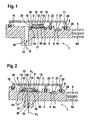
- Fig. 1 shows a first embodiment of a sensor module, which is designed as a pressure sensor module for absolute pressure measurement.
- the pressure sensor module 1 has a sensor housing 1 with a first housing part 2, which is manufactured as an injection molded part with electrical conductors 4 partially embedded therein.
- the electrical conductors 4 may be formed, for example, as stamped grid parts, wherein a plurality of electrically separate leadframe tracks are embedded in the plastic of the housing part 1.
- the electrical conductors 4 may be guided on one side of the sensor housing 1 to a plug-in connection 5 of the sensor module, where connecting portions 4d of the conductors or connector pins connected thereto are excluded from the plastic sheath.
- a second housing part 3 is provided as a lid, which is for example also made of plastic as an injection molded part and is mounted on the first housing part 1.
- a partition wall 22 and a peripheral wall 29 is formed on the second housing part 3.
- the two housing parts connected in this way form a sensor housing with a first inner space 10 and a second inner space 11, wherein the second inner space is separated from the first inner space 10 by the dividing wall 22 and is sealed off from it, so that different atmospheres and pressures occur in the two inner spaces can exist.
- the first housing part 2 further has a pressure port 20 with a pressure channel 21, which opens into the first inner space 10, so that a pressure P applied to the pressure port 20 also prevails in the inner space 10.
- the electrical conductors 4 have connection sections 4a, 4b and 4c, which are not embedded in the plastic of the housing part 2, but the inside of the first housing part 2 facing the first interior 10 or the second interior 11 of the sensor housing are excluded from the serving.
- At least one capacitor 7 arranged in the second housing interior 11 is contacted with a connection section 4c of an electrical conductor 4, preferably by means of a conductive adhesive arranged between the connection section 4c and the capacitor 7.
- the capacitor 7 is a protective capacitor for improving the electromagnetic compatibility (EMC protection) of the sensor module and for protection against electrostatic discharges. It is therefore arranged between the connection sections 4d of the plug connection 5 and connection sections 4a, 4b, which are provided for contacting the sensor arrangement.
- the sensor arrangement 12, 13 comprises a sensor element 12, for example a semiconductor pressure sensor with a silicon chip, on the upper side of which pressure-sensitive elements are arranged, and a base 13.
- the sensor arrangement is inserted into a box-shaped receiving part 6 (premold), which has a through a receptacle 18 has a bottom 17 and a peripheral wall 16 formed.
- the receiving part 6 may for example consist of plastic.
- the receiving part 6 further comprises connecting elements 19, which from the receptacle 18 by the circumferential Wall 16 are guided in the first inner space 10 and there with the disposed on the inside of the first housing part 2 connecting portions 4a, 4b (in Fig. 1 By way of example, two connection sections 4a and 4b are shown) of the electrical conductors 4, for example by welding.
- connection sections 4a, 4b it is, of course, also possible to produce the electrical connection of the electrical connection elements 19 to the connection sections 4a, 4b by soldering or press-contacting or in another suitable manner.
- the not connected to the conductors 4 ends of the connecting elements 19 are connected in the interior of the receptacle 18, for example via bonding wire connections to the sensor element 12.
- the receptacle 18 of the receiving part 6 is to protect the sensor element with a protective cover 14, such as a gel, filled. When pressure is applied to the interior 10, the pressure is transmitted to the sensor element 12 via the elastic gel.
- the inner side of the first housing part 2 facing the first inner space 10 has a second receptacle 26 which is formed by a depression on the inner side of the first housing part 2 and has a circumferential wall 25 delimiting the second receptacle 26.
- the receiving part 6 is disposed within the bounded by the peripheral wall 25 receptacle 26. Between the wall 25 and the receiving part 6 is a the electrical connection point of the electrical conductors 4 and the electrical connection elements 19 covering material 9, for example, an adhesive, in particular a silicone adhesive arranged.
- the adhesive can advantageously be applied to the first housing part 1 together with the filling of the grooves 28.
- Fig. 2 shows an embodiment with a trained for reference pressure measurement sensor module. Same things are with the same reference numbers as in Fig. 1 Mistake.
- the receiving part 6 is arranged above the pressure channel 21 and provided with a recess in the bottom 17 for carrying out a pressure P1.
- the base 13 also has a recess, so that the sensor membrane of the sensor element 12 can be acted upon from below with a first pressure P1, which does not prevail in the first interior space 10, since the pressure channel 21 is sealed here against the first interior 10.
- the second housing part 3 has a second pressure port 30, through which the first inner space 10 and the resilient cover 14 made of gel, the upper side of the sensor membrane of the sensor element 12 with a pressure P2 can be acted upon as a reference pressure.
- the sensor element 12 and the bonding wire connection to the connection elements 19 are particularly well protected against damage, since air which could reach the first interior space 10 from the second interior space 11 along the plastic conductors 4 injected in plastic, There exits below the covering material and therefore can not cause damage to the bonding wire connection, since the bonding wire connection is protected against the ingress of air within the receiving part 6 is arranged.
Landscapes
- Physics & Mathematics (AREA)
- General Physics & Mathematics (AREA)
- Electromagnetism (AREA)
- Measuring Fluid Pressure (AREA)
- Pressure Sensors (AREA)
Abstract
Claims (9)
- Module de détecteur, en particulier module de détecteur de pression, qui présente
un boîtier de détecteur (1) doté d'une partie de boîtier (2) dans laquelle des conducteurs électriques (4) sont partiellement incorporés,
un premier espace intérieur (10) dans lequel un système de détecteur (12, 13) est disposé et un deuxième espace intérieur (11) séparé hermétiquement du premier espace intérieur (10) et dans lequel au moins un condensateur (7) est disposé étant prévus dans le boîtier de détecteur,
le boîtier de détecteur présentant une première partie de boîtier (2) et au moins une deuxième partie de boîtier (3),
une paroi de séparation (22) étant formée sur la première partie de boîtier (2) ou la deuxième partie de boîtier (3),
le premier espace intérieur (10) et le deuxième espace intérieur (11) étant formés en plaçant la deuxième partie de boîtier (3) sur la première partie de boîtier (2),
une partie de réception (6) qui présente un logement (18) formé par une paroi périphérique (16) étant disposée dans le premier espace intérieur (10),
le système de détecteur (12, 13) étant inséré dans le logement et étant recouvert par un recouvrement de protection (14) injecté dans le logement (18),
le boîtier de détecteur présentant un raccordement de pression (20, 30) par lequel une pression (P1, P2) peut être appliquée dans le premier espace intérieur (11) et un élément de détecteur (12) du système de détecteur,
le système de détecteur (12, 13) étant mis en contact avec des éléments de raccordement électriques (19) disposés dans la partie de réception (6),
les éléments de raccordement (19) étant prolongés depuis le logement (18) jusque dans le premier espace intérieur (10) et reliés directement par des parties de raccordement (4a, 4b) à des conducteurs électriques (4) disposés dans le premier espace intérieur (10) sur la première partie de boîtier (2),
le ou les condensateurs (7) disposés dans le deuxième espace intérieur (11) étant reliés par un matériau électriquement conducteur (27) à au moins l'un des conducteurs électriques (4). - Module de détecteur selon la revendication 1, caractérisé en ce que la partie de réception (6) est insérée dans un deuxième logement (26) formé sur la partie de boîtier (2), le deuxième logement présentant une paroi (25) qui entoure la partie de réception (6), et en ce qu'un matériau (9), en particulier un adhésif, qui recouvre l'emplacement de raccordement électrique des conducteurs électriques (4) et des éléments (19) de raccordement électriques est placé entre la paroi (25) qui entoure la partie de réception et la partie de réception (6).
- Module de détecteur selon la revendication 1, caractérisé en ce que le boîtier de détecteur (1) présente une première partie de boîtier (2) réalisée sous la forme d'une pièce moulée par injection dans laquelle les conducteurs électriques (4) sont incorporés partiellement sous la forme de pièces en treillis estampé, les pièces en treillis estampé conduisant sur un côté du boîtier de détecteur à une borne de raccordement (5) du module de détecteur.
- Module de détecteur selon la revendication 1, caractérisé en ce qu'une paroi périphérique (29) de la deuxième partie de boîtier (3) et une paroi de séparation (22) formée sur la deuxième partie de boîtier (3) s'engagent dans des rainures (28) formées sur la première partie de boîtier (2) et remplies d'un matériau d'étanchéité (8) ou en ce qu'une paroi périphérique de la première partie de boîtier et une paroi de séparation formée sur la deuxième partie de boîtier s'engagent dans des rainures formées sur la deuxième partie de boîtier et remplies d'un matériau d'étanchéité.
- Module de détecteur selon la revendication 1, caractérisé en ce que le boîtier présente une première partie de boîtier (2) et une deuxième partie de boîtier (3), en ce que le module de détecteur est un module de détecteur de pression relative qui présente deux raccordements de pression (20, 30), en ce que la partie de réception (6) est disposée avec son fond (17) au-dessus de l'un (20) des deux raccordements de pression et est dotée d'un logement prévu dans son fond (17) pour amener une pression (P1) et en ce que la première partie de boîtier (2) est recouverte par une deuxième partie de boîtier (3) qui présente l'autre raccordement de pression.
- Module de détecteur selon la revendication 1, caractérisé en ce que les éléments (19) de raccordement électriques de la partie de réception (6) sont soudés aux conducteurs électriques (4) de la partie de boîtier (2) .
- Module de détecteur selon la revendication 1, caractérisé en ce que le matériau électriquement conducteur (27) est un adhésif conducteur.
- Module de détecteur selon l'une des revendications précédentes, caractérisé en ce que le système de détecteur (12, 13) comprend une puce (12) de détection de pression en silicium appliquée sur un socle (13) et mise en contact au moyen de fils de liaison avec les éléments (19) de raccordement électriques de la partie de réception (6).
- Module de détecteur selon la revendication 1, caractérisé en ce que le condensateur (7) est au moins un condensateur de protection EMV.
Applications Claiming Priority (2)
| Application Number | Priority Date | Filing Date | Title |
|---|---|---|---|
| DE102004012593A DE102004012593A1 (de) | 2004-03-12 | 2004-03-12 | Sensormodul |
| PCT/EP2004/052986 WO2005088268A1 (fr) | 2004-03-12 | 2004-11-17 | Module de capteurs comportant une protection de compatibilite electromagnetique et contre les decharges electrostatiques a condensateurs |
Publications (2)
| Publication Number | Publication Date |
|---|---|
| EP1728060A1 EP1728060A1 (fr) | 2006-12-06 |
| EP1728060B1 true EP1728060B1 (fr) | 2011-02-09 |
Family
ID=34895389
Family Applications (1)
| Application Number | Title | Priority Date | Filing Date |
|---|---|---|---|
| EP04821722A Expired - Lifetime EP1728060B1 (fr) | 2004-03-12 | 2004-11-17 | Module de capteurs comportant une protection de compatibilite electromagnetique et contre les decharges electrostatiques a condensateurs |
Country Status (5)
| Country | Link |
|---|---|
| US (1) | US7426868B2 (fr) |
| EP (1) | EP1728060B1 (fr) |
| JP (1) | JP2007501937A (fr) |
| DE (2) | DE102004012593A1 (fr) |
| WO (1) | WO2005088268A1 (fr) |
Families Citing this family (28)
| Publication number | Priority date | Publication date | Assignee | Title |
|---|---|---|---|---|
| JP5490349B2 (ja) * | 2006-05-24 | 2014-05-14 | 株式会社デンソー | 圧力センサ |
| DE102007029720A1 (de) * | 2007-06-27 | 2009-01-08 | Robert Bosch Gmbh | Baugruppe mit einem ASIC und einem Gehäuse für den ASIC |
| DE102007054717B4 (de) * | 2007-11-14 | 2010-09-30 | Inor Process Ab | Transmitter und Verfahren zur Herstellung eines Transmitters |
| DE102008005153A1 (de) | 2008-01-18 | 2009-07-23 | Robert Bosch Gmbh | Druckmessmodul |
| DE102009000597B4 (de) * | 2009-02-04 | 2020-10-15 | Robert Bosch Gmbh | Haltekörper zur spielfreien Montage von Sensoren |
| EP2224218B1 (fr) * | 2009-02-25 | 2018-11-28 | Sensirion Automotive Solutions AG | Capteur dans un emballage moulé et son procédé de fabrication |
| DE102009028966A1 (de) * | 2009-08-28 | 2011-03-03 | Robert Bosch Gmbh | Drucksensor |
| US8390083B2 (en) | 2009-09-04 | 2013-03-05 | Analog Devices, Inc. | System with recessed sensing or processing elements |
| DE102009054734A1 (de) | 2009-12-16 | 2011-06-22 | Robert Bosch GmbH, 70469 | Drucksensoranordnung |
| DE102010001075A1 (de) * | 2010-01-21 | 2011-07-28 | Robert Bosch GmbH, 70469 | Niederdrucksensor |
| DE102010001418A1 (de) * | 2010-02-01 | 2011-08-04 | Robert Bosch GmbH, 70469 | Sensormodul, Verfahren zur Herstellung eines Sensormoduls |
| DE102010039599A1 (de) | 2010-08-20 | 2012-02-23 | Robert Bosch Gmbh | Sensormodul zur Aufnahme eines Drucksensorchips und zur Montage in einem Sensorgehäuse |
| US9407997B2 (en) | 2010-10-12 | 2016-08-02 | Invensense, Inc. | Microphone package with embedded ASIC |
| DE102011079446A1 (de) * | 2011-07-20 | 2013-02-07 | Robert Bosch Gmbh | Sensoreinrichtung, insbesondere für die Verwendung in einem Kraftfahrzeug |
| US12247810B2 (en) | 2013-03-21 | 2025-03-11 | Nostromo, Llc | Optically tracked projectile |
| CN104576883B (zh) | 2013-10-29 | 2018-11-16 | 普因特工程有限公司 | 芯片安装用阵列基板及其制造方法 |
| KR101438571B1 (ko) * | 2013-11-25 | 2014-09-12 | 한국지질자원연구원 | 유도형 광대역 3성분 시추공 자기장 계측센서 및 이를 이용한 시추공 전자탐사방법 |
| JP5870989B2 (ja) * | 2013-12-03 | 2016-03-01 | 株式会社デンソー | 車両用圧力検出装置 |
| DE102014221067A1 (de) * | 2014-10-16 | 2016-04-21 | Robert Bosch Gmbh | Drucksensor zur Erfassung eines Drucks eines fluiden Mediums |
| DE102014225861A1 (de) * | 2014-12-15 | 2016-06-16 | Robert Bosch Gmbh | Sensoreinrichtung, insbesondere für die Verwendung in einem Kraftfahrzeug |
| US9666558B2 (en) | 2015-06-29 | 2017-05-30 | Point Engineering Co., Ltd. | Substrate for mounting a chip and chip package using the substrate |
| DE102015223850A1 (de) * | 2015-12-01 | 2017-06-01 | Robert Bosch Gmbh | Verfahren zur Herstellung einer Vorrichtung zur Erfassung mindestens einer Eigenschaft eines fluiden Mediums in einem Messraum |
| US10060820B2 (en) * | 2015-12-22 | 2018-08-28 | Continental Automotive Systems, Inc. | Stress-isolated absolute pressure sensor |
| US10215655B2 (en) | 2015-12-31 | 2019-02-26 | Honeywell International Inc. | Pressure sensor assembly |
| JPWO2017138647A1 (ja) * | 2016-02-10 | 2018-11-29 | 日本電産トーソク株式会社 | 圧力検出装置とその製造方法 |
| JP6471118B2 (ja) | 2016-05-24 | 2019-02-13 | 日本電産トーソク株式会社 | 圧力検出装置、および圧力検出装置を格納した電動油圧ポンプ |
| CN209326840U (zh) | 2018-12-27 | 2019-08-30 | 热敏碟公司 | 压力传感器及压力变送器 |
| DE102021134430A1 (de) * | 2021-12-22 | 2023-06-22 | Systec Automotive Gmbh | Vorrichtung zur Druck-, Kraft- oder Temperaturmessung |
Family Cites Families (7)
| Publication number | Priority date | Publication date | Assignee | Title |
|---|---|---|---|---|
| US5948991A (en) | 1996-12-09 | 1999-09-07 | Denso Corporation | Semiconductor physical quantity sensor device having semiconductor sensor chip integrated with semiconductor circuit chip |
| DE19731420A1 (de) | 1997-07-22 | 1999-01-28 | Bosch Gmbh Robert | Vorrichtung zur Erfassung des Drucks und der Temperatur im Saugrohr einer Brennkraftmaschine und Verfahren zu ihrer Herstellung |
| JP3452835B2 (ja) | 1999-05-28 | 2003-10-06 | 三菱電機株式会社 | 圧力センサ装置 |
| DE10052406A1 (de) * | 2000-10-20 | 2002-05-23 | Bosch Gmbh Robert | Drucksensormodul |
| DE10054013B4 (de) | 2000-11-01 | 2007-06-21 | Robert Bosch Gmbh | Drucksensormodul |
| DE10223357A1 (de) * | 2002-05-25 | 2003-12-04 | Bosch Gmbh Robert | Vorrichtung zur Druckmessung |
| DE10331967A1 (de) * | 2003-07-15 | 2005-02-03 | Robert Bosch Gmbh | Sensoreinrichtung |
-
2004
- 2004-03-12 DE DE102004012593A patent/DE102004012593A1/de not_active Withdrawn
- 2004-11-17 EP EP04821722A patent/EP1728060B1/fr not_active Expired - Lifetime
- 2004-11-17 JP JP2006523019A patent/JP2007501937A/ja active Pending
- 2004-11-17 DE DE502004012185T patent/DE502004012185D1/de not_active Expired - Lifetime
- 2004-11-17 WO PCT/EP2004/052986 patent/WO2005088268A1/fr not_active Ceased
- 2004-11-17 US US10/592,631 patent/US7426868B2/en not_active Expired - Lifetime
Also Published As
| Publication number | Publication date |
|---|---|
| US20080034877A1 (en) | 2008-02-14 |
| DE502004012185D1 (de) | 2011-03-24 |
| WO2005088268A1 (fr) | 2005-09-22 |
| DE102004012593A1 (de) | 2005-09-29 |
| JP2007501937A (ja) | 2007-02-01 |
| EP1728060A1 (fr) | 2006-12-06 |
| US7426868B2 (en) | 2008-09-23 |
Similar Documents
| Publication | Publication Date | Title |
|---|---|---|
| EP1728060B1 (fr) | Module de capteurs comportant une protection de compatibilite electromagnetique et contre les decharges electrostatiques a condensateurs | |
| DE102012208361B4 (de) | Druckmessvorrichtung und Verfahren zum Herstellen derselbigen | |
| DE19936300B4 (de) | Druckerkennungsvorrichtung und Druckerkennungsvorrichtung-Anordnung hiermit | |
| DE102008005153A1 (de) | Druckmessmodul | |
| EP2606329B1 (fr) | Module capteur pour loger une puce de capteur de pression et à monter dans un boîtier de capteur | |
| EP1718937B1 (fr) | Support de capteur et procede de realisation associe | |
| WO1993005635A1 (fr) | Appareil electrique, en particulier appareil de commutation et de commande pour vehicules a moteur | |
| DE102016110659B4 (de) | Mold-Gehäusestruktur mit Klebstoff-Auslaufstopper zum Abdichten eines MEMS-Bauelements und Verfahren zum Verpacken eines MEMS-Bauelements | |
| EP2586280A2 (fr) | Ensemble électrique pour un véhicule automobile, approprié pour la connexion avec un connecteur | |
| DE19755767A1 (de) | Gehäuse mit Steckereinheit | |
| EP3549414B1 (fr) | Ensemble électrique | |
| DE102007041785A1 (de) | Halbleitervorrichtung und deren Herstellungsverfahren | |
| DE19816216C2 (de) | Elektrischer Stecker und Steckverbindung | |
| DE102010061750A1 (de) | Bauteil mit einer elektronischen Einrichtung und Verfahren zu dessen Herstellung | |
| DE102014200936A1 (de) | Elektronikbaugruppe | |
| DE19902450B4 (de) | Miniaturisiertes elektronisches System und zu dessen Herstellung geeignetes Verfahren | |
| DE102013215365A1 (de) | Elektrische Getriebesteuervorrichtung und Herstellungsverfahren | |
| DE102005053876B4 (de) | Drucksensor-Bauteil | |
| EP2255603A1 (fr) | Dispositif pour recevoir un composant électrique/électronique et procédé de montage correspondant, et élément de recouvrement pour un tel dispositif | |
| DE102006030805B4 (de) | EMV Optimierung für Sensorgehäuse | |
| EP1658760B1 (fr) | Coque d'encapsulation | |
| DE19516936A1 (de) | Metallgehäuse mit integrierter Steckerbuchse | |
| DE102009027382A1 (de) | Elektronisches Bauteil mit EMV-Schutz | |
| EP4120481B1 (fr) | Ensemble de connexion | |
| DE202005017626U1 (de) | Drucksensor-Bauteil |
Legal Events
| Date | Code | Title | Description |
|---|---|---|---|
| PUAI | Public reference made under article 153(3) epc to a published international application that has entered the european phase |
Free format text: ORIGINAL CODE: 0009012 |
|
| 17P | Request for examination filed |
Effective date: 20061012 |
|
| AK | Designated contracting states |
Kind code of ref document: A1 Designated state(s): DE FR |
|
| DAX | Request for extension of the european patent (deleted) | ||
| RBV | Designated contracting states (corrected) |
Designated state(s): DE FR |
|
| 17Q | First examination report despatched |
Effective date: 20090123 |
|
| GRAP | Despatch of communication of intention to grant a patent |
Free format text: ORIGINAL CODE: EPIDOSNIGR1 |
|
| GRAS | Grant fee paid |
Free format text: ORIGINAL CODE: EPIDOSNIGR3 |
|
| GRAA | (expected) grant |
Free format text: ORIGINAL CODE: 0009210 |
|
| AK | Designated contracting states |
Kind code of ref document: B1 Designated state(s): DE FR |
|
| REF | Corresponds to: |
Ref document number: 502004012185 Country of ref document: DE Date of ref document: 20110324 Kind code of ref document: P |
|
| REG | Reference to a national code |
Ref country code: DE Ref legal event code: R096 Ref document number: 502004012185 Country of ref document: DE Effective date: 20110324 |
|
| PLBE | No opposition filed within time limit |
Free format text: ORIGINAL CODE: 0009261 |
|
| STAA | Information on the status of an ep patent application or granted ep patent |
Free format text: STATUS: NO OPPOSITION FILED WITHIN TIME LIMIT |
|
| 26N | No opposition filed |
Effective date: 20111110 |
|
| REG | Reference to a national code |
Ref country code: DE Ref legal event code: R097 Ref document number: 502004012185 Country of ref document: DE Effective date: 20111110 |
|
| REG | Reference to a national code |
Ref country code: FR Ref legal event code: PLFP Year of fee payment: 12 |
|
| REG | Reference to a national code |
Ref country code: FR Ref legal event code: PLFP Year of fee payment: 13 |
|
| REG | Reference to a national code |
Ref country code: FR Ref legal event code: PLFP Year of fee payment: 14 |
|
| PGFP | Annual fee paid to national office [announced via postgrant information from national office to epo] |
Ref country code: FR Payment date: 20231123 Year of fee payment: 20 |
|
| PGFP | Annual fee paid to national office [announced via postgrant information from national office to epo] |
Ref country code: DE Payment date: 20240123 Year of fee payment: 20 |
|
| REG | Reference to a national code |
Ref country code: DE Ref legal event code: R071 Ref document number: 502004012185 Country of ref document: DE |