EP1728087B1 - Blindage contre les courants de foucault perfore pour aimant principal dans dispositif d'imagerie par resonance magnetique - Google Patents
Blindage contre les courants de foucault perfore pour aimant principal dans dispositif d'imagerie par resonance magnetique Download PDFInfo
- Publication number
- EP1728087B1 EP1728087B1 EP05708970A EP05708970A EP1728087B1 EP 1728087 B1 EP1728087 B1 EP 1728087B1 EP 05708970 A EP05708970 A EP 05708970A EP 05708970 A EP05708970 A EP 05708970A EP 1728087 B1 EP1728087 B1 EP 1728087B1
- Authority
- EP
- European Patent Office
- Prior art keywords
- eddy current
- resonance imaging
- magnetic resonance
- imaging device
- main magnet
- Prior art date
- Legal status (The legal status is an assumption and is not a legal conclusion. Google has not performed a legal analysis and makes no representation as to the accuracy of the status listed.)
- Not-in-force
Links
Images
Classifications
-
- G—PHYSICS
- G01—MEASURING; TESTING
- G01R—MEASURING ELECTRIC VARIABLES; MEASURING MAGNETIC VARIABLES
- G01R33/00—Arrangements or instruments for measuring magnetic variables
- G01R33/20—Arrangements or instruments for measuring magnetic variables involving magnetic resonance
- G01R33/28—Details of apparatus provided for in groups G01R33/44 - G01R33/64
- G01R33/38—Systems for generation, homogenisation or stabilisation of the main or gradient magnetic field
- G01R33/385—Systems for generation, homogenisation or stabilisation of the main or gradient magnetic field using gradient magnetic field coils
- G01R33/3854—Systems for generation, homogenisation or stabilisation of the main or gradient magnetic field using gradient magnetic field coils means for active and/or passive vibration damping or acoustical noise suppression in gradient magnet coil systems
-
- G—PHYSICS
- G01—MEASURING; TESTING
- G01R—MEASURING ELECTRIC VARIABLES; MEASURING MAGNETIC VARIABLES
- G01R33/00—Arrangements or instruments for measuring magnetic variables
- G01R33/20—Arrangements or instruments for measuring magnetic variables involving magnetic resonance
- G01R33/28—Details of apparatus provided for in groups G01R33/44 - G01R33/64
- G01R33/42—Screening
- G01R33/421—Screening of main or gradient magnetic field
- G01R33/4215—Screening of main or gradient magnetic field of the gradient magnetic field, e.g. using passive or active shielding of the gradient magnetic field
Definitions
- the present invention relates to a magnetic resonance imaging device, comprising at least a main magnet system for generating a steady magnetic field in a measuring space of the magnetic resonance imaging device, a gradient system for generating a magnetic gradient field in said measuring space, and an eddy current shield system.
- US 5,028,872 discloses a magnetic resonance imaging (MRI) system, which includes a main shield member arranged in the cylindrical housing; and a sub shield member which is electrically connected to the main shield member and is arranged outside the housing to cover a region where the object under examination is placed.
- MRI magnetic resonance imaging
- the basic components of a magnetic resonance imaging (MRI) device are the main magnet system, the gradient system, the RF system and the signal processing system.
- the main magnet system is also often called cryostat.
- the main magnet system comprises a bore hole defining a measuring space and enabling the entry of an object to be analyzed by the MRI device.
- the main magnet system generates a strong uniform static field for polarization of nuclear spins in the object to be analyzed.
- the gradient system is designed to produce time-varying magnetic fields of controlled spatial non-uniformity.
- the gradient system is a crucial part of the MRI device because gradient fields are essential for signal localization.
- the RF system mainly consists of a transmitter coil and a receiver coil, wherein the transmitter coil is capable of generating a magnetic field for excitation of a spin system, and wherein the receiver coil converts a precessing magnetization into electrical signals.
- the signal processing system generates images on basis of the electrical signals.
- Magnetic resonance imaging (MRI) devices known from prior art usually generate a relatively high acoustic noise level which has to be minimized.
- acoustic noise is caused by vibrations of the gradient system
- acoustic noise is caused by vibrations of the main magnet system (cryostat).
- the acoustic noise generated by the gradient system vibrations can effectively be reduced by means of a vacuum chamber. See for example US 6,404,200 and US 5,793,210 .
- the main magnet system vibrations are caused by three excitation mechanisms, firstly by a structural transmission of vibrations from the gradient system to the main magnet system through gradient coil mounts, secondly by a magnetic excitation of the main magnet system due to the varying magnetic gradient-fields causing eddy currents in the wall of the main magnet system, and thirdly by an acoustic excitation of the main magnet system.
- the third excitation mechanism is not dominant for most MRI devices.
- the first excitation mechanism causing vibrations of the main magnet system can be reduced effectively by using a compliant support for the gradient coils of the gradient system. See for example EP-A-1 193 507 .
- a magnetic resonance imaging device in accordance with the invention is characterized in that the or each perforated eddy current screen is flexibly connected to the main magnet system.
- the or each perforated eddy current screen is designed in a way that the degree of perforation is in the range of 0.1% to 95%, most preferably in the range of 10% to 50%.
- the or each perforated eddy current screen is designed as a constraining layer structure, wherein the constraining layer structure comprises preferably two perforated plate-like layers, especially made from copper, and one perforated visco-elastic layer made from a visco-elastic material. The visco-elastic layer is sandwiched between the two plate-like layers.
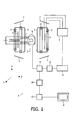
- Figure 1 shows a magnetic resonance imaging (MRI) device 1 known from prior art which includes a main magnet system 2 for generating a steady magnetic field, and also several gradient coils providing a gradient system 3 for generating additional magnetic fields having a gradient in the X, Y, Z directions.
- the Z direction of the coordinate system shown corresponds to the direction of the steady magnetic field in the main magnet system 2 by convention.
- the Z axis is an axis co-axial with the axis of a bore hole of the main magnet system 2, wherein the X axis is the vertical axis extending from the center of the magnetic field, and wherein the Y axis is the corresponding horizontal axis orthogonal to the Z axis and the X axis.
- the gradient coils of the gradient system 3 are fed by a power supply unit 4.
- An RF transmitter coil 5 serves to generate RF magnetic fields and is connected to an RF transmitter and modulator 6.
- a receiver coil is used to receive the magnetic resonance signal generated by the RF field in the object 7 to be examined, for example a human or animal body. This coil may be the same coil as the RF transmitter coil 5.
- the main magnet system 2 encloses an examination space which is large enough to accommodate a part of the body 7 to be examined.
- the RF coil 5 is arranged around or on the part of the body 7 to be examined in this examination space.
- the RF transmitter coil 5 is connected to a signal amplifier and demodulation unit 10 via a transmission/reception circuit 9.
- the control unit 11 controls the RF transmitter and modulator 6 and the power supply unit 4 so as to generate special pulse sequences which contain RF pulses and gradients.
- the phase and amplitude obtained from the demodulation unit 10 are applied to a processing unit 12.
- the processing unit 12 processes the presented signal values so as to form an image by transformation. This image can be visualized, for example by means of a monitor 8.
- the present invention provides a passive shielding to reduce the acoustic noise level generated by magnetic resonance imaging devices due to the magnetic exitation of the main magnet system due the varying magnetic gradient-fields causing eddy currents in the wall of the main magnet system.
- the magnetic resonance imaging device comprises an eddy current shield system, wherein the eddy current shield system comprises at least one perforated eddy current screen, and wherein the or each perforated eddy current screen is preferably flexibly connected to the main magnet system.
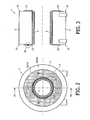
- the magnetic resonance imaging device 1 comprises two eddy current screens 13, 14, wherein at each lateral flange 15, 16 of the main magnet system 2 there is positioned one of said eddy current screens 13, 14.
- the eddy current screens 13, 14 are designed as perforated eddy current screens.
- the degree of perforation should be as low as possible.
- the degree of perforation should be as high as possible.
- a high degree of perforation reduces the acoustic radiation of the vibrating eddy current screens 13, 14. It should be noted, that the vibrations of the eddy current screens 13, 14 are caused by eddy currents in the eddy current screens 13, 14 that cause Lorentz forces acting upon the eddy current screens 13, 14.
- the perforated eddy current screens 13, 14 are designed in a way that the degree of perforation is in the range of 0.1 % to 95%, preferably in the range of 10% to 50%. Especially the range of 10% to 50% provides a good compromise between the required shielding properties and acoustic properties of the eddy current screens 13, 14.
- Figure 5 shows the enlarged detail V according to figure 2 and illustrates the perforated structure of the eddy current screens 13, 14.
- the eddy current screens 13, 14 are designed as plate-like elements, a plurality of holes 17 being formed into the plate-like elements of the eddy current screens 13, 14.
- the degree of perforation is approximately 30 %. This would mean that the hole-area of the eddy current screens 13, 14 is approximately 30 % of the total area of the eddy current screens 13, 14.
- the eddy current screens 13, 14 are characterized by a thickness being thin enough or small enough in order to minimize radiation of acoustic noise and being thick enough in order to shield the magnetic field radiated by the gradient coils of the gradient system 3 effectively.
- the critical frequency f c of the eddy current screens 13, 14 should be greater than the frequency of the acoustic noise generated by the magnetic imaging device 1.
- Magnet resonance imaging devices generate usually acoustic noise dominated around 1000 Hz, ranging from 500 Hz to 2000 Hz.
- the skin depth of the eddy current screens 13, 14 should be in a range that magnetic fields for frequencies of 500 Hz and higher are sufficiently shielded.
- the thickness of the eddy current screens 13, 14 should be in the range of the skin depth, or larger, in order to provide sufficient magnetic shielding.
- the thickness of the perforated eddy current screens 13, 14 made from copper are characterized by a thickness in the range of 0,01 mm to 10 mm, preferably in the range of 1 mm to 5 mm. Most preferably the eddy current screens 13, 14 have a thickness of 3 mm.
- the thickness of the eddy current screens 13, 14 is increased in the region in which the eddy current screens 13, 14 are mounted to the main magnet system 2. In these locations, the eddy current screens 13, 14 preferably have a thickness of approximately 8 mm. With the increased thickness of the eddy current screens 13, 14 at the mounting locations, it is possible to improve the isolation of the eddy current screens 13, 14 from the main magnet system 2. An alternative way to improve the isolation is to use an extra mass on the eddy current screens 13, 14 in the region of the mounting locations.
- the eddy current screens 13, 14 are flexibly connected to the main magnet system 2 by elastic mounting means 18.
- the elastic mounting means 18 are preferably designed as flexible rubber means.
- the eddy current screens 13, 14 are designed as constraining layer structures
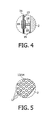
- figure 4 shows a constraining layer structure of the eddy current screen 13 comprising two plate-like layers 19, 20 preferably made from copper and one visco-elastic layer 21 sandwiched between the two plate-like layers 19, 20.
- the two plate-like layers 19, 20 and the visco-elastic layer 21 are all perforated according to the present invention.
- Such a constraining layer structure provides a high amount of the structural damping, and thus a reduced vibration level of the perforated eddy current screen.
- the eddy current screens 13, 14 are positioned in the region of the two lateral flanges 15, 16 of the main magnet system 2. With such an arrangement it is possible to reduce the eddy currents in the flanges 15, 16 of the main magnet system 2.
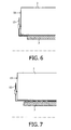
- Figure 6 shows a modification of the present invention in which the eddy current screens 13, 14 extend into the bore hole of the main magnet system 2.
- the eddy current screens 13, 14 shield the lateral flanges 15, 16 of the main magnet system 2 and in addition the outer ends of the bore hole.
- the eddy current screens 13, 14 shield both lateral flanges 15, 16 of the main magnet system 2 and the complete bore hole.
- the eddy current screens 13, 14 are positioned in the region of the two lateral flanges 15, 16 of the main magnet system 2 and in addition in the region of the bore hole, within the bore hole the eddy current screens being positioned between the main magnet system 2 and the gradient system 3.
- the present invention provides a magnetic resonance imaging device with a eddy current shield system comprising at least one perforated eddy current screen.
- a perforated eddy current screen With such a perforated eddy current screen the acoustic noise caused by the magnetic exitation of the main magnet system due to the varying magnetic gradient-fields can be efficiently shielded.
- Perforated eddy current screens provide a passive shielding mechanism.
Landscapes
- Physics & Mathematics (AREA)
- Condensed Matter Physics & Semiconductors (AREA)
- General Physics & Mathematics (AREA)
- Health & Medical Sciences (AREA)
- Epidemiology (AREA)
- Magnetic Resonance Imaging Apparatus (AREA)
- Shielding Devices Or Components To Electric Or Magnetic Fields (AREA)
Claims (14)
- Dispositif d'imagerie par résonance magnétique, comprenant au moins:a) un système d'aimant principal (2) pour générer un champ magnétique constant dans un espace de mesure du dispositif d'imagerie par résonance magnétique,b) un système de gradients (3) pour générer un champ de gradient magnétique dans ledit espace de mesure; etc) un système de blindage contre les courants de Foucault qui comprend au moins un écran perforé (13, 14) pour courants de Foucault, caractérisé en ce que l'écran perforé ou chaque écran perforé (13, 14) pour courants de Foucault est relié de façon flexible au système d'aimant principal (2).
- Dispositif d'imagerie par résonance magnétique suivant la revendication 1, caractérisé en ce que l'écran perforé ou chaque écran perforé (13, 14) pour courants de Foucault est conçu d'une manière telle que le degré de perforation soit situé dans l'intervalle de 0,1% à 95%.
- Dispositif d'imagerie par résonance magnétique suivant la revendication 2, caractérisé en ce que l'écran perforé ou chaque écran perforé (13, 14) pour courants de Foucault est conçu d'une manière telle que le degré de perforation soit situé dans l'intervalle de 10% à 50%.
- Dispositif d'imagerie par résonance magnétique suivant la revendication 1, caractérisé en ce que l'écran perforé ou chaque écran perforé (13, 14) pour courants de Foucault est conçu comme une structure de contrainte multicouche, ladite structure de contrainte multicouche comprenant au moins une couche du type plaque perforée (19, 20) et au moins une couche viscoélastique perforée (21).
- Dispositif d'imagerie par résonance magnétique suivant la revendication 4, caractérisé en ce que la structure de contrainte multicouche comprend deux couches du type plaque perforée (19, 20) et une couche viscoélastique perforée (21), ladite couche viscoélastique (21) étant prise en sandwich entre les deux couches du type plaque (19, 20).
- Dispositif d'imagerie par résonance magnétique suivant la revendication 1, caractérisé en ce que l'écran ou chaque écran (13, 14) pour courants de Foucault a une épaisseur qui est suffisamment mince pour minimaliser le rayonnement du bruit acoustique et suffisamment épaisse pour maximaliser le blindage contre le champ magnétique rayonné par le système de gradients (3).
- Dispositif d'imagerie par résonance magnétique suivant la revendication 6, caractérisé en ce que l'écran ou chaque écran pour courants de Foucault (13, 14) a une épaisseur comprise située dans l'intervalle de 0,01 mm à 10 mm.
- Dispositif d'imagerie par résonance magnétique suivant la revendication 7, caractérisé en ce que l'écran ou chaque écran pour courants de Foucault (13, 14) a une épaisseur située dans l'intervalle de 1 mm à 5 mm.
- Dispositif d'imagerie par résonance magnétique suivant la revendication 6, caractérisé en ce que l'écran ou chaque écran pour courants de Foucault (13, 14) a une épaisseur accrue dans la région dans laquelle l'écran pour courants de Foucault (13, 14) est monté sur le système d'aimant principal (2).
- Dispositif d'imagerie par résonance magnétique suivant la revendication 1, caractérisé en ce que l'écran ou chaque écran pour courants de Foucault (13, 14) est fixé de manière flexible au système d'aimant principal (2) par des moyens de montage élastiques (18), spécialement par des moyens en caoutchouc souples.
- Dispositif d'imagerie par résonance magnétique suivant la revendication 1, caractérisé en ce que l'écran ou chaque écran pour courants de Foucault (13, 14) est positionné au moins dans la région des deux joues latérales (15, 16) du système d'aimant principal (2).
- Dispositif d'imagerie par résonance magnétique suivant la revendication 11, caractérisé en ce que l'écran ou chaque écran pour courants de Foucault (13, 14) est positionné dans la région des joues latérales (15, 16) du système d'aimant principal (2) et, en outre, dans la région du tunnel entre le système d'aimant principal (2) et le système de gradients (3).
- Dispositif d'imagerie par résonance magnétique suivant la revendication 1, caractérisé en ce que l'écran ou chaque écran pour courants de Foucault (13, 14) est positionné au moins dans la région du tunnel entre le système d'aimant principal (2) et le système de gradients (3)
- Dispositif d'imagerie par résonance magnétique suivant la revendication 13, caractérisé en ce que l'écran ou chaque écran pour courants de Foucault (13, 14) est positionné dans la région du tunnel et, en outre, dans la région des joues latérales (15, 16) du système d'aimant principal (2).
Priority Applications (1)
| Application Number | Priority Date | Filing Date | Title |
|---|---|---|---|
| EP05708970A EP1728087B1 (fr) | 2004-03-15 | 2005-03-08 | Blindage contre les courants de foucault perfore pour aimant principal dans dispositif d'imagerie par resonance magnetique |
Applications Claiming Priority (3)
| Application Number | Priority Date | Filing Date | Title |
|---|---|---|---|
| EP04101051 | 2004-03-15 | ||
| EP05708970A EP1728087B1 (fr) | 2004-03-15 | 2005-03-08 | Blindage contre les courants de foucault perfore pour aimant principal dans dispositif d'imagerie par resonance magnetique |
| PCT/IB2005/050844 WO2005091009A1 (fr) | 2004-03-15 | 2005-03-08 | Blindage contre les courants de foucault perfore pour aimant principal dans dispositif d'imagerie par resonance magnetique |
Publications (2)
| Publication Number | Publication Date |
|---|---|
| EP1728087A1 EP1728087A1 (fr) | 2006-12-06 |
| EP1728087B1 true EP1728087B1 (fr) | 2008-05-28 |
Family
ID=34960931
Family Applications (1)
| Application Number | Title | Priority Date | Filing Date |
|---|---|---|---|
| EP05708970A Not-in-force EP1728087B1 (fr) | 2004-03-15 | 2005-03-08 | Blindage contre les courants de foucault perfore pour aimant principal dans dispositif d'imagerie par resonance magnetique |
Country Status (7)
| Country | Link |
|---|---|
| US (1) | US7372271B2 (fr) |
| EP (1) | EP1728087B1 (fr) |
| JP (1) | JP2007529259A (fr) |
| CN (1) | CN1930484A (fr) |
| AT (1) | ATE397222T1 (fr) |
| DE (1) | DE602005007196D1 (fr) |
| WO (1) | WO2005091009A1 (fr) |
Cited By (1)
| Publication number | Priority date | Publication date | Assignee | Title |
|---|---|---|---|---|
| US8487727B2 (en) | 2010-09-17 | 2013-07-16 | General Electric Company | Magnet assemblies and methods for making the same |
Families Citing this family (37)
| Publication number | Priority date | Publication date | Assignee | Title |
|---|---|---|---|---|
| CN1886671A (zh) * | 2003-11-25 | 2006-12-27 | 皇家飞利浦电子股份有限公司 | 包括附加涡流屏蔽系统的有源屏蔽梯度线圈系统 |
| JP2008152835A (ja) * | 2006-12-15 | 2008-07-03 | Hitachi Global Storage Technologies Netherlands Bv | 磁気抵抗効果ヘッド、磁気記録再生装置及び磁気ヘッドの製造方法 |
| US8183860B2 (en) * | 2006-12-20 | 2012-05-22 | Koninklijke Philips Electronics N.V. | Arrangement and method for influencing and/or detecting magnetic particles in a region of action |
| AU2010273298B2 (en) * | 2009-07-15 | 2014-10-23 | Viewray Technologies, Inc. | Method and apparatus for shielding a linear accelerator and a magnetic resonance imaging device from each other |
| US20110166438A1 (en) * | 2009-12-17 | 2011-07-07 | Emerson Jane F | Rf field shaping and attenuation for emai induction elements |
| GB2487215B (en) * | 2011-01-13 | 2014-12-10 | Siemens Plc | Electrically conductive shield for superconducting electromagnet system |
| DE102011082401B4 (de) * | 2011-09-09 | 2015-01-08 | Siemens Aktiengesellschaft | Magnetresonanzvorrichtung |
| US9279871B2 (en) | 2011-12-20 | 2016-03-08 | General Electric Company | System and apparatus for compensating for magnetic field distortion in an MRI system |
| US9322892B2 (en) | 2011-12-20 | 2016-04-26 | General Electric Company | System for magnetic field distortion compensation and method of making same |
| DE102011089445B4 (de) * | 2011-12-21 | 2015-11-05 | Siemens Aktiengesellschaft | Verfahren und Gradientensystem zur Reduzierung von mechanischen Schwingungen in einem Magnetresonanzbildgebungssystem |
| DE102012013534B3 (de) | 2012-07-05 | 2013-09-19 | Tobias Sokolowski | Vorrichtung für repetitive Nervenstimulation zum Abbau von Fettgewebe mittels induktiver Magnetfelder |
| US9274188B2 (en) | 2012-11-30 | 2016-03-01 | General Electric Company | System and apparatus for compensating for magnetic field distortion in an MRI system |
| US11491342B2 (en) | 2015-07-01 | 2022-11-08 | Btl Medical Solutions A.S. | Magnetic stimulation methods and devices for therapeutic treatments |
| US10821295B1 (en) | 2015-07-01 | 2020-11-03 | Btl Medical Technologies S.R.O. | Aesthetic method of biological structure treatment by magnetic field |
| US20180001107A1 (en) | 2016-07-01 | 2018-01-04 | Btl Holdings Limited | Aesthetic method of biological structure treatment by magnetic field |
| US11266850B2 (en) | 2015-07-01 | 2022-03-08 | Btl Healthcare Technologies A.S. | High power time varying magnetic field therapy |
| US10695575B1 (en) | 2016-05-10 | 2020-06-30 | Btl Medical Technologies S.R.O. | Aesthetic method of biological structure treatment by magnetic field |
| US11253717B2 (en) | 2015-10-29 | 2022-02-22 | Btl Healthcare Technologies A.S. | Aesthetic method of biological structure treatment by magnetic field |
| JP6699977B2 (ja) * | 2016-03-09 | 2020-05-27 | シナプティヴ メディカル (バルバドス) インコーポレイテッドSynaptive Medical (Barbados) Inc. | 磁気共鳴システムにおける機械式クライオクーラの発振によって引き起こされる磁場の不安定性の低減 |
| US11247039B2 (en) | 2016-05-03 | 2022-02-15 | Btl Healthcare Technologies A.S. | Device including RF source of energy and vacuum system |
| US11464993B2 (en) | 2016-05-03 | 2022-10-11 | Btl Healthcare Technologies A.S. | Device including RF source of energy and vacuum system |
| US11534619B2 (en) | 2016-05-10 | 2022-12-27 | Btl Medical Solutions A.S. | Aesthetic method of biological structure treatment by magnetic field |
| US10583287B2 (en) | 2016-05-23 | 2020-03-10 | Btl Medical Technologies S.R.O. | Systems and methods for tissue treatment |
| US10556122B1 (en) | 2016-07-01 | 2020-02-11 | Btl Medical Technologies S.R.O. | Aesthetic method of biological structure treatment by magnetic field |
| US11141219B1 (en) | 2016-08-16 | 2021-10-12 | BTL Healthcare Technologies, a.s. | Self-operating belt |
| DE102016225347A1 (de) * | 2016-12-16 | 2018-06-21 | Bruker Biospin Gmbh | MRI-System mit Spaltstruktur in einer Abschirmrohr-Anordnung |
| CN106772162B (zh) * | 2016-12-26 | 2020-01-14 | 中国科学院长春光学精密机械与物理研究所 | 用于磁共振成像系统的非缠绕形式梯度线圈及其设计方法 |
| EP3952984B1 (fr) | 2019-04-11 | 2024-09-04 | BTL Medical Solutions a.s. | Dispositifs de traitement esthétique de structures biologiques par radiofréquence et énergie magnétique |
| US12558146B2 (en) | 2019-04-11 | 2026-02-24 | Btl Medical Solutions A.S. | Methods and devices for aesthetic treatment of biological structures by radiofrequency and magnetic energy |
| US12156689B2 (en) | 2019-04-11 | 2024-12-03 | Btl Medical Solutions A.S. | Methods and devices for aesthetic treatment of biological structures by radiofrequency and magnetic energy |
| JP2023515722A (ja) | 2020-05-04 | 2023-04-13 | ビーティーエル ヘルスケア テクノロジーズ エー.エス. | 患者の非アテンド式治療のためのデバイスおよび方法 |
| US11878167B2 (en) | 2020-05-04 | 2024-01-23 | Btl Healthcare Technologies A.S. | Device and method for unattended treatment of a patient |
| US12611545B2 (en) | 2020-05-04 | 2026-04-28 | Btl Healthcare Technologies A.S. | Device and method for unattended treatment of a patient |
| CA3260012A1 (fr) | 2021-10-13 | 2023-04-20 | Btl Medical Solutions A.S. | Dispositifs de traitement esthétique de structures biologiques par énergie radiofréquence et magnétique |
| US11896816B2 (en) | 2021-11-03 | 2024-02-13 | Btl Healthcare Technologies A.S. | Device and method for unattended treatment of a patient |
| JP2024036043A (ja) * | 2022-09-05 | 2024-03-15 | キヤノンメディカルシステムズ株式会社 | 静磁場磁石及び磁気共鳴イメージング装置 |
| US20260097226A1 (en) | 2024-10-08 | 2026-04-09 | Btl Medical Solutions A.S. | Devices and methods for application of a magnetic field to the nervous system |
Family Cites Families (17)
| Publication number | Priority date | Publication date | Assignee | Title |
|---|---|---|---|---|
| DE3511750A1 (de) * | 1985-03-30 | 1986-10-09 | Philips Patentverwaltung Gmbh, 2000 Hamburg | Spulenanordnung fuer kernspinuntersuchungen |
| JPS63122442A (ja) * | 1986-11-12 | 1988-05-26 | 株式会社東芝 | 磁気共鳴イメ−ジング装置 |
| JPH0687444B2 (ja) * | 1986-12-22 | 1994-11-02 | 株式会社東芝 | 磁気共鳴映像装置 |
| JPS63216553A (ja) * | 1987-03-06 | 1988-09-08 | 株式会社東芝 | Mri用rfセルフシ−ルド |
| JPH0722576B2 (ja) * | 1988-04-11 | 1995-03-15 | 三菱電機株式会社 | 磁気共鳴装置 |
| JPH01288246A (ja) * | 1988-05-16 | 1989-11-20 | Toshiba Corp | 磁気共鳴イメージング装置 |
| DE3833592A1 (de) * | 1988-10-03 | 1990-04-05 | Philips Patentverwaltung | Vorrichtung zur geraeuschdaempfung und hochfrequenz-abschirmung des patienten-aufnahmeraumes im feld des magneten eines mr-tomographiegeraetes |
| JPH0323840A (ja) * | 1989-06-21 | 1991-01-31 | Toshiba Corp | Mri装置用超電導マグネット |
| US5539367A (en) * | 1994-05-02 | 1996-07-23 | General Electric Company | Superconducting gradient shields in magnetic resonance imaging magnets |
| JP3524607B2 (ja) * | 1995-01-09 | 2004-05-10 | 株式会社日立メディコ | 磁気共鳴イメージング装置用磁場発生コイル及びこれを用いた磁気共鳴イメージング装置 |
| EP1189212A3 (fr) | 1995-03-28 | 2003-09-17 | Toray Industries, Inc. | Supports d'enregistrement optique et procédé d'enregistrement pour les supports d'enregistrement optique |
| US5550472A (en) * | 1995-04-13 | 1996-08-27 | Picker International, Inc. | Combined radio frequency coil with integral magnetic field shim set |
| US5793210A (en) * | 1996-08-13 | 1998-08-11 | General Electric Company | Low noise MRI scanner |
| WO1999028757A1 (fr) * | 1997-11-28 | 1999-06-10 | Koninklijke Philips Electronics N.V. | Appareil a resonance magnetique dote de bobines a gradient optimise par rapport a la force |
| EP1046053A1 (fr) * | 1998-10-28 | 2000-10-25 | Koninklijke Philips Electronics N.V. | Dispositif d'imagerie par resonance magnetique, dote d'un blindage contre les courants d'eddy, integre mecaniquement dans le systeme de gradient |
| DE19940550C1 (de) * | 1999-08-26 | 2001-05-23 | Siemens Ag | Magnetresonanztomographiegerät mit vakuumisoliertem Gradientenspulensystem |
| US6437568B1 (en) | 2000-10-02 | 2002-08-20 | General Electric Company | Low noise MRI scanner |
-
2005
- 2005-03-08 US US10/598,670 patent/US7372271B2/en not_active Expired - Fee Related
- 2005-03-08 CN CNA2005800082157A patent/CN1930484A/zh active Pending
- 2005-03-08 DE DE602005007196T patent/DE602005007196D1/de not_active Expired - Fee Related
- 2005-03-08 WO PCT/IB2005/050844 patent/WO2005091009A1/fr not_active Ceased
- 2005-03-08 JP JP2007503472A patent/JP2007529259A/ja active Pending
- 2005-03-08 EP EP05708970A patent/EP1728087B1/fr not_active Not-in-force
- 2005-03-08 AT AT05708970T patent/ATE397222T1/de not_active IP Right Cessation
Cited By (1)
| Publication number | Priority date | Publication date | Assignee | Title |
|---|---|---|---|---|
| US8487727B2 (en) | 2010-09-17 | 2013-07-16 | General Electric Company | Magnet assemblies and methods for making the same |
Also Published As
| Publication number | Publication date |
|---|---|
| CN1930484A (zh) | 2007-03-14 |
| JP2007529259A (ja) | 2007-10-25 |
| US7372271B2 (en) | 2008-05-13 |
| US20070176602A1 (en) | 2007-08-02 |
| DE602005007196D1 (de) | 2008-07-10 |
| EP1728087A1 (fr) | 2006-12-06 |
| ATE397222T1 (de) | 2008-06-15 |
| WO2005091009A1 (fr) | 2005-09-29 |
Similar Documents
| Publication | Publication Date | Title |
|---|---|---|
| EP1728087B1 (fr) | Blindage contre les courants de foucault perfore pour aimant principal dans dispositif d'imagerie par resonance magnetique | |
| EP1193507B1 (fr) | Scanner IRM à faible bruit | |
| EP2845037B1 (fr) | Bobine radiofréquence (rf) de réduction de bruit acoustique pour imagerie à résonance magnétique | |
| US7375526B2 (en) | Active-passive electromagnetic shielding to reduce MRI acoustic noise | |
| JP4037272B2 (ja) | 磁気共鳴イメージング装置及びそれに用いられる静磁場発生装置 | |
| US7141974B2 (en) | Active-passive electromagnetic shielding to reduce MRI acoustic noise | |
| US20080315878A1 (en) | Actively Shielded Gradient Coil System Comprising Additional Additional Eddy Current Shield System | |
| US8779773B2 (en) | Thermoacoustic RF body coil liner for reduced acoustic noise in an MR system | |
| CN103688184B (zh) | 一种用于mr扫描设备的rf体线圈 | |
| JP3897958B2 (ja) | 磁気共鳴イメージング装置 | |
| JP3394933B2 (ja) | 磁気共鳴イメージング装置 | |
| JP3618171B2 (ja) | 磁気共鳴イメージング装置 | |
| US6538439B1 (en) | MRI apparatus including a vacuum isolated gradient coil | |
| US20070182516A1 (en) | Magnetic resonance imaging device with an active shielding device | |
| US20200064422A1 (en) | Acoustic generator for mri devices, and mri device provided with same | |
| JP2002085371A (ja) | 磁気共鳴イメージング装置 | |
| JP2005160842A (ja) | 磁気共鳴イメージング装置 | |
| JPH01212413A (ja) | 核磁気共鳴形診断装置のマグネット構造 | |
| JPH04231934A (ja) | 磁気共鳴イメージング装置 | |
| WO2006062028A1 (fr) | Systeme d’imagerie par resonance magnetique | |
| JP2002143123A (ja) | Mri装置 | |
| JPH01291848A (ja) | 磁気共鳴イメージング装置 | |
| JP2015053982A (ja) | 磁気共鳴イメージング装置 | |
| JP2005261806A (ja) | 磁気共鳴イメージング装置 |
Legal Events
| Date | Code | Title | Description |
|---|---|---|---|
| PUAI | Public reference made under article 153(3) epc to a published international application that has entered the european phase |
Free format text: ORIGINAL CODE: 0009012 |
|
| 17P | Request for examination filed |
Effective date: 20061016 |
|
| AK | Designated contracting states |
Kind code of ref document: A1 Designated state(s): AT BE BG CH CY CZ DE DK EE ES FI FR GB GR HU IE IS IT LI LT LU MC NL PL PT RO SE SI SK TR |
|
| DAX | Request for extension of the european patent (deleted) | ||
| GRAP | Despatch of communication of intention to grant a patent |
Free format text: ORIGINAL CODE: EPIDOSNIGR1 |
|
| 17Q | First examination report despatched |
Effective date: 20071029 |
|
| GRAS | Grant fee paid |
Free format text: ORIGINAL CODE: EPIDOSNIGR3 |
|
| GRAA | (expected) grant |
Free format text: ORIGINAL CODE: 0009210 |
|
| AK | Designated contracting states |
Kind code of ref document: B1 Designated state(s): AT BE BG CH CY CZ DE DK EE ES FI FR GB GR HU IE IS IT LI LT LU MC NL PL PT RO SE SI SK TR |
|
| REG | Reference to a national code |
Ref country code: GB Ref legal event code: FG4D |
|
| REG | Reference to a national code |
Ref country code: CH Ref legal event code: EP |
|
| REF | Corresponds to: |
Ref document number: 602005007196 Country of ref document: DE Date of ref document: 20080710 Kind code of ref document: P |
|
| REG | Reference to a national code |
Ref country code: IE Ref legal event code: FG4D |
|
| PG25 | Lapsed in a contracting state [announced via postgrant information from national office to epo] |
Ref country code: SI Free format text: LAPSE BECAUSE OF FAILURE TO SUBMIT A TRANSLATION OF THE DESCRIPTION OR TO PAY THE FEE WITHIN THE PRESCRIBED TIME-LIMIT Effective date: 20080528 |
|
| PG25 | Lapsed in a contracting state [announced via postgrant information from national office to epo] |
Ref country code: FI Free format text: LAPSE BECAUSE OF FAILURE TO SUBMIT A TRANSLATION OF THE DESCRIPTION OR TO PAY THE FEE WITHIN THE PRESCRIBED TIME-LIMIT Effective date: 20080528 Ref country code: ES Free format text: LAPSE BECAUSE OF FAILURE TO SUBMIT A TRANSLATION OF THE DESCRIPTION OR TO PAY THE FEE WITHIN THE PRESCRIBED TIME-LIMIT Effective date: 20080908 |
|
| PG25 | Lapsed in a contracting state [announced via postgrant information from national office to epo] |
Ref country code: NL Free format text: LAPSE BECAUSE OF FAILURE TO SUBMIT A TRANSLATION OF THE DESCRIPTION OR TO PAY THE FEE WITHIN THE PRESCRIBED TIME-LIMIT Effective date: 20080528 Ref country code: AT Free format text: LAPSE BECAUSE OF FAILURE TO SUBMIT A TRANSLATION OF THE DESCRIPTION OR TO PAY THE FEE WITHIN THE PRESCRIBED TIME-LIMIT Effective date: 20080528 |
|
| NLV1 | Nl: lapsed or annulled due to failure to fulfill the requirements of art. 29p and 29m of the patents act | ||
| PG25 | Lapsed in a contracting state [announced via postgrant information from national office to epo] |
Ref country code: IS Free format text: LAPSE BECAUSE OF FAILURE TO SUBMIT A TRANSLATION OF THE DESCRIPTION OR TO PAY THE FEE WITHIN THE PRESCRIBED TIME-LIMIT Effective date: 20080928 |
|
| PG25 | Lapsed in a contracting state [announced via postgrant information from national office to epo] |
Ref country code: DK Free format text: LAPSE BECAUSE OF FAILURE TO SUBMIT A TRANSLATION OF THE DESCRIPTION OR TO PAY THE FEE WITHIN THE PRESCRIBED TIME-LIMIT Effective date: 20080528 Ref country code: LT Free format text: LAPSE BECAUSE OF FAILURE TO SUBMIT A TRANSLATION OF THE DESCRIPTION OR TO PAY THE FEE WITHIN THE PRESCRIBED TIME-LIMIT Effective date: 20080528 Ref country code: SE Free format text: LAPSE BECAUSE OF FAILURE TO SUBMIT A TRANSLATION OF THE DESCRIPTION OR TO PAY THE FEE WITHIN THE PRESCRIBED TIME-LIMIT Effective date: 20080828 Ref country code: CZ Free format text: LAPSE BECAUSE OF FAILURE TO SUBMIT A TRANSLATION OF THE DESCRIPTION OR TO PAY THE FEE WITHIN THE PRESCRIBED TIME-LIMIT Effective date: 20080528 |
|
| PG25 | Lapsed in a contracting state [announced via postgrant information from national office to epo] |
Ref country code: SK Free format text: LAPSE BECAUSE OF FAILURE TO SUBMIT A TRANSLATION OF THE DESCRIPTION OR TO PAY THE FEE WITHIN THE PRESCRIBED TIME-LIMIT Effective date: 20080528 Ref country code: RO Free format text: LAPSE BECAUSE OF FAILURE TO SUBMIT A TRANSLATION OF THE DESCRIPTION OR TO PAY THE FEE WITHIN THE PRESCRIBED TIME-LIMIT Effective date: 20080528 Ref country code: PT Free format text: LAPSE BECAUSE OF FAILURE TO SUBMIT A TRANSLATION OF THE DESCRIPTION OR TO PAY THE FEE WITHIN THE PRESCRIBED TIME-LIMIT Effective date: 20081028 Ref country code: BE Free format text: LAPSE BECAUSE OF FAILURE TO SUBMIT A TRANSLATION OF THE DESCRIPTION OR TO PAY THE FEE WITHIN THE PRESCRIBED TIME-LIMIT Effective date: 20080528 |
|
| PLBE | No opposition filed within time limit |
Free format text: ORIGINAL CODE: 0009261 |
|
| STAA | Information on the status of an ep patent application or granted ep patent |
Free format text: STATUS: NO OPPOSITION FILED WITHIN TIME LIMIT |
|
| PG25 | Lapsed in a contracting state [announced via postgrant information from national office to epo] |
Ref country code: EE Free format text: LAPSE BECAUSE OF FAILURE TO SUBMIT A TRANSLATION OF THE DESCRIPTION OR TO PAY THE FEE WITHIN THE PRESCRIBED TIME-LIMIT Effective date: 20080528 Ref country code: BG Free format text: LAPSE BECAUSE OF FAILURE TO SUBMIT A TRANSLATION OF THE DESCRIPTION OR TO PAY THE FEE WITHIN THE PRESCRIBED TIME-LIMIT Effective date: 20080828 |
|
| 26N | No opposition filed |
Effective date: 20090303 |
|
| PG25 | Lapsed in a contracting state [announced via postgrant information from national office to epo] |
Ref country code: IT Free format text: LAPSE BECAUSE OF FAILURE TO SUBMIT A TRANSLATION OF THE DESCRIPTION OR TO PAY THE FEE WITHIN THE PRESCRIBED TIME-LIMIT Effective date: 20080528 |
|
| PGFP | Annual fee paid to national office [announced via postgrant information from national office to epo] |
Ref country code: DE Payment date: 20090512 Year of fee payment: 5 Ref country code: FR Payment date: 20090330 Year of fee payment: 5 |
|
| PG25 | Lapsed in a contracting state [announced via postgrant information from national office to epo] |
Ref country code: MC Free format text: LAPSE BECAUSE OF NON-PAYMENT OF DUE FEES Effective date: 20090331 |
|
| REG | Reference to a national code |
Ref country code: CH Ref legal event code: PL |
|
| GBPC | Gb: european patent ceased through non-payment of renewal fee |
Effective date: 20090308 |
|
| REG | Reference to a national code |
Ref country code: IE Ref legal event code: MM4A |
|
| PG25 | Lapsed in a contracting state [announced via postgrant information from national office to epo] |
Ref country code: IE Free format text: LAPSE BECAUSE OF NON-PAYMENT OF DUE FEES Effective date: 20090308 Ref country code: CH Free format text: LAPSE BECAUSE OF NON-PAYMENT OF DUE FEES Effective date: 20090331 Ref country code: LI Free format text: LAPSE BECAUSE OF NON-PAYMENT OF DUE FEES Effective date: 20090331 |
|
| PG25 | Lapsed in a contracting state [announced via postgrant information from national office to epo] |
Ref country code: GB Free format text: LAPSE BECAUSE OF NON-PAYMENT OF DUE FEES Effective date: 20090308 |
|
| PG25 | Lapsed in a contracting state [announced via postgrant information from national office to epo] |
Ref country code: PL Free format text: LAPSE BECAUSE OF FAILURE TO SUBMIT A TRANSLATION OF THE DESCRIPTION OR TO PAY THE FEE WITHIN THE PRESCRIBED TIME-LIMIT Effective date: 20080528 |
|
| PG25 | Lapsed in a contracting state [announced via postgrant information from national office to epo] |
Ref country code: GR Free format text: LAPSE BECAUSE OF FAILURE TO SUBMIT A TRANSLATION OF THE DESCRIPTION OR TO PAY THE FEE WITHIN THE PRESCRIBED TIME-LIMIT Effective date: 20080829 |
|
| REG | Reference to a national code |
Ref country code: FR Ref legal event code: ST Effective date: 20101130 |
|
| PG25 | Lapsed in a contracting state [announced via postgrant information from national office to epo] |
Ref country code: FR Free format text: LAPSE BECAUSE OF NON-PAYMENT OF DUE FEES Effective date: 20100331 |
|
| PG25 | Lapsed in a contracting state [announced via postgrant information from national office to epo] |
Ref country code: DE Free format text: LAPSE BECAUSE OF NON-PAYMENT OF DUE FEES Effective date: 20101001 |
|
| PG25 | Lapsed in a contracting state [announced via postgrant information from national office to epo] |
Ref country code: LU Free format text: LAPSE BECAUSE OF NON-PAYMENT OF DUE FEES Effective date: 20090308 |
|
| PG25 | Lapsed in a contracting state [announced via postgrant information from national office to epo] |
Ref country code: HU Free format text: LAPSE BECAUSE OF FAILURE TO SUBMIT A TRANSLATION OF THE DESCRIPTION OR TO PAY THE FEE WITHIN THE PRESCRIBED TIME-LIMIT Effective date: 20081129 |
|
| PG25 | Lapsed in a contracting state [announced via postgrant information from national office to epo] |
Ref country code: TR Free format text: LAPSE BECAUSE OF FAILURE TO SUBMIT A TRANSLATION OF THE DESCRIPTION OR TO PAY THE FEE WITHIN THE PRESCRIBED TIME-LIMIT Effective date: 20080528 |
|
| PG25 | Lapsed in a contracting state [announced via postgrant information from national office to epo] |
Ref country code: CY Free format text: LAPSE BECAUSE OF FAILURE TO SUBMIT A TRANSLATION OF THE DESCRIPTION OR TO PAY THE FEE WITHIN THE PRESCRIBED TIME-LIMIT Effective date: 20080528 |