EP1728462A2 - Instrument für Endoscope und Instrumentsystem für Endoscope. - Google Patents
Instrument für Endoscope und Instrumentsystem für Endoscope. Download PDFInfo
- Publication number
- EP1728462A2 EP1728462A2 EP06010911A EP06010911A EP1728462A2 EP 1728462 A2 EP1728462 A2 EP 1728462A2 EP 06010911 A EP06010911 A EP 06010911A EP 06010911 A EP06010911 A EP 06010911A EP 1728462 A2 EP1728462 A2 EP 1728462A2
- Authority
- EP
- European Patent Office
- Prior art keywords
- section
- electrode section
- electrode
- instrument
- distal end
- Prior art date
- Legal status (The legal status is an assumption and is not a legal conclusion. Google has not performed a legal analysis and makes no representation as to the accuracy of the status listed.)
- Granted
Links
Images


Classifications
-
- A—HUMAN NECESSITIES
- A61—MEDICAL OR VETERINARY SCIENCE; HYGIENE
- A61B—DIAGNOSIS; SURGERY; IDENTIFICATION
- A61B18/00—Surgical instruments, devices or methods for transferring non-mechanical forms of energy to or from the body
- A61B18/04—Surgical instruments, devices or methods for transferring non-mechanical forms of energy to or from the body by heating
- A61B18/12—Surgical instruments, devices or methods for transferring non-mechanical forms of energy to or from the body by heating by passing a current through the tissue to be heated, e.g. high-frequency current
- A61B18/14—Probes or electrodes therefor
- A61B18/1492—Probes or electrodes therefor having a flexible, catheter-like structure, e.g. for heart ablation
-
- A—HUMAN NECESSITIES
- A61—MEDICAL OR VETERINARY SCIENCE; HYGIENE
- A61B—DIAGNOSIS; SURGERY; IDENTIFICATION
- A61B18/00—Surgical instruments, devices or methods for transferring non-mechanical forms of energy to or from the body
- A61B18/04—Surgical instruments, devices or methods for transferring non-mechanical forms of energy to or from the body by heating
- A61B18/12—Surgical instruments, devices or methods for transferring non-mechanical forms of energy to or from the body by heating by passing a current through the tissue to be heated, e.g. high-frequency current
- A61B18/14—Probes or electrodes therefor
- A61B18/1477—Needle-like probes
-
- A—HUMAN NECESSITIES
- A61—MEDICAL OR VETERINARY SCIENCE; HYGIENE
- A61B—DIAGNOSIS; SURGERY; IDENTIFICATION
- A61B18/00—Surgical instruments, devices or methods for transferring non-mechanical forms of energy to or from the body
- A61B18/04—Surgical instruments, devices or methods for transferring non-mechanical forms of energy to or from the body by heating
- A61B18/12—Surgical instruments, devices or methods for transferring non-mechanical forms of energy to or from the body by heating by passing a current through the tissue to be heated, e.g. high-frequency current
- A61B18/14—Probes or electrodes therefor
- A61B2018/1405—Electrodes having a specific shape
- A61B2018/1422—Hook
-
- A—HUMAN NECESSITIES
- A61—MEDICAL OR VETERINARY SCIENCE; HYGIENE
- A61B—DIAGNOSIS; SURGERY; IDENTIFICATION
- A61B18/00—Surgical instruments, devices or methods for transferring non-mechanical forms of energy to or from the body
- A61B18/04—Surgical instruments, devices or methods for transferring non-mechanical forms of energy to or from the body by heating
- A61B18/12—Surgical instruments, devices or methods for transferring non-mechanical forms of energy to or from the body by heating by passing a current through the tissue to be heated, e.g. high-frequency current
- A61B18/14—Probes or electrodes therefor
- A61B2018/1405—Electrodes having a specific shape
- A61B2018/1425—Needle
-
- A—HUMAN NECESSITIES
- A61—MEDICAL OR VETERINARY SCIENCE; HYGIENE
- A61B—DIAGNOSIS; SURGERY; IDENTIFICATION
- A61B18/00—Surgical instruments, devices or methods for transferring non-mechanical forms of energy to or from the body
- A61B18/04—Surgical instruments, devices or methods for transferring non-mechanical forms of energy to or from the body by heating
- A61B18/12—Surgical instruments, devices or methods for transferring non-mechanical forms of energy to or from the body by heating by passing a current through the tissue to be heated, e.g. high-frequency current
- A61B18/14—Probes or electrodes therefor
- A61B2018/1405—Electrodes having a specific shape
- A61B2018/144—Wire
-
- A—HUMAN NECESSITIES
- A61—MEDICAL OR VETERINARY SCIENCE; HYGIENE
- A61B—DIAGNOSIS; SURGERY; IDENTIFICATION
- A61B18/00—Surgical instruments, devices or methods for transferring non-mechanical forms of energy to or from the body
- A61B18/04—Surgical instruments, devices or methods for transferring non-mechanical forms of energy to or from the body by heating
- A61B18/12—Surgical instruments, devices or methods for transferring non-mechanical forms of energy to or from the body by heating by passing a current through the tissue to be heated, e.g. high-frequency current
- A61B18/14—Probes or electrodes therefor
- A61B2018/1475—Electrodes retractable in or deployable from a housing
Definitions
- the present invention relates to an instrument for an endoscope such as a high frequency knife for resecting living tissues, in particular, a high frequency knife used for endoscopic submucosal dissection (hereinafter abbreviated as "ESD”), and also to an instrument system for an endoscope having the instrument for an endoscope.
- ESD endoscopic submucosal dissection
- Treatments for resecting living tissues such as mucosa using endoscopes have been performed conventionally and ESD such as resecting lesions formed on the surface of the digestive tract by dissecting submucosa to resect the affected area after circumferential incision of normal mucosa in the outer side of the affected area has been carried out.
- the living tissue When dissection of living tissue is carried out, the living tissue is locally cauterized and dissected by applying high frequency current (current for dissection) to an electrode section such as a scalpel whose contact area with the living tissue is small.
- an electrode section such as a scalpel whose contact area with the living tissue is small.
- the bleeding site and the living tissue around it is cauterized to carry out blood coagulation procedures by applying a current different from the one applied at the time of dissection (current for coagulation) to an electrode section with a shape such as of a sphere whose contact area with the living tissue is large.
- an electrode rod for resection (refer to patent document 1, for instance) capable of shortening the time spent on dissection and coagulation treatments, a single pole polyp resecting snare provided with a coagulation electrode (refer to patent document 2, for instance), and the like are known for resolving such inconveniences.
- the electrode rod for resection described in patent document 1 is equipped with electrodes for both dissection and coagulation at the distal end of the main body thereof. Therefore, it is possible to apply current to both electrodes simultaneously by applying current to a conducting section provided on the proximal end side of the electrode rod main body. It is possible to carry out dissection and coagulation treatments rapidly by making the respective electrodes contact the living tissue alternately.
- the single pole polyp resecting snare provided with a coagulation electrode described in patent document 2 is equipped with a ring-shaped surface electrode (electrode for coagulation) with a large contact area with the living tissue at the distal end of a tubular plastic member.
- a conductive snare loop (electrode for dissection) arranged so as to be freely movable forward and backward inside the plastic member and capable of ligating living tissues.
- the surface electrode and loop are electrically connected to cords having plugs at their ends so as to be connectable separately to jacks of their electrosurgical oscillator.
- the present invention was made by taking the aforementioned problems of the prior art into consideration and its object is to provide an instrument for an endoscope and an instrument system for an endoscope which make it possible to perform dissection and coagulation treatments by rapidly using electrode sections with appropriate shapes for each purpose separately, which require less labor, and also capable of reducing the burden on the patient by shortening the time spent for the procedures.
- the present invention provides the means below in order to achieve the above objects.
- the invention according to a first aspect provides an instrument for an endoscope having an insulative insertion section inserted in a channel of an endoscope and having flexibility, a tubular first electrode section arranged at the distal end of the insertion section and on which an insertion hole is formed along the axis of the insertion section, a conductive electric wire inserted in the insertion section so as to be freely movable forwards and backwards, a control section arranged on the proximal end side of the insertion section and controlling forward/backward movement of the electric wire along the axial direction, a rod-shaped second electrode section connected to the distal end of the electric wire and inserted so as to be freely movable forwards and backwards inside the insertion hole, and an external connecting section electrically connected to the proximal end side of the electric wire and applying external currents with predetermined frequencies to the electric wire and the second electrode section, wherein the second electrode section protrudes from and retracts into the distal end of the first electrode section in response to the movement control by the control
- an endoscope insertion section is firstly inserted into the coelom and after the distal end of the endoscope insertion section is placed in the vicinity of the living tissue where the dissection treatment will be performed, the insertion section is inserted in the channel so as to protrude from the distal end of the endoscope insertion section.
- the second electrode section can be made to retract into the first electrode section.
- the rod-shaped second electrode section is made to protrude from the distal end of the first electrode section by moving the control section to the distal end side. Subsequently, the entire insertion section or the entire endoscope insertion section is moved towards the living tissue to make the second electrode section contact the living tissue. In this state, an external current with a predetermined frequency, that is, the current for dissection is applied to the external connecting section. Since the current for dissection is applied to the second electrode section via the external connection section and the electric wire in this procedure, the living tissue contacting the second electrode section can be locally cauterized and dissected. In particular, since the second electrode section is rod shaped with a relatively small contact area with the living tissue, it is possible to carry out the dissection treatment reliably by using the current for dissection, where the energy density is enhanced.
- the application of the current for dissection is stopped and the control section is moved to the proximal end side of the insertion section to retract the second electrode section into the first electrode section.
- the first and second electrode sections are electrically connected by this procedure.
- a current with a different frequency to that applied during the dissection treatment that is, the current for coagulation is applied to the external connection section after moving the control section to the proximal end side.
- the current for coagulation is applied to the first electrode section via the external connection section, electric wire, and second electrode section.
- the entire insertion section or the entire endoscope insertion section is then moved toward the living tissue and the distal end of the first electrode section (including the second electrode section) is pressed against the living tissue, including the bleeding site.
- coagulation treatment for cauterizing the bleeding site and the living tissue around it to stop bleeding can be performed.
- the coagulation treatment can be carried out at the distal end of the first electrode section, formed in a tubular shape with a relatively large area, coagulation treatment can be performed reliably using the current for coagulation, where the energy density is lowered.
- the dissection or coagulation treatment can be carried out more reliably since when performing the dissection or coagulation treatment, electrode sections (the first and second electrode sections) with appropriate shapes for each treatment can be used alternately and separately with currents with appropriate frequencies.
- the invention according to a second aspect provides the instrument for an endoscope according to the first aspect, wherein the first electrode section is formed so that an inner circumferential surface thereof is in an electrically insulative state.
- the current for dissection is not applied to the first electrode section during dissection treatment using the second electrode section even if the second electrode section contacts the insertion hole.
- the dissection treatment can be carried out safely without any problems even when the first electrode section contacts the endoscope channel or living tissue.
- the invention according to a third aspect provides the instrument for an endoscope according to the first or second aspect, having a recess formed at the distal end of the first electrode section so as to surround the periphery of the opening of the insertion hole, and a salient arranged at the distal end of the second electrode section and which extends in the direction perpendicular to the axial direction, wherein the salient is contained in the recess when the second electrode section retracts into the first electrode section.
- the instrument for an endoscope it is possible to dissect while hooking living tissue onto the salient when performing the dissection treatment since the salient is formed at the distal end of the second electrode section. Accordingly, the dissection treatment can be performed more reliably. Moreover, the distal end of the first electrode section will be a surface without asperities since the salient is contained in the recess when the coagulation treatment is performed. Thus, it is possible to carry out haemostasis by cauterizing living tissue uniformly when the first electrode section is pressed against the living tissue.
- the first and second electrode sections can be electrically connected reliably since the salient and recess contact when the salient is contained in the recess, Furthermore, trouble due to entry of foreign materials can be avoided as much as possible since the entry of contamination or the like from the opening of the insertion hole into the first electrode section can be prevented when performing the coagulation treatment.
- the invention according to a fourth aspect provides the instrument for an endoscope according to the third aspect, having a stopper member which is arranged in-between the electric wire and the second electrode section, which contacts the proximal end side of the first electrode section to regulate the extent of protrusion of the second electrode section when the second electrode section protrudes and which provides insulation to the first electrode section when it makes contact with the proximal end side of the first electrode section.
- the stopper member contacts the proximal end side of the first electrode section when the control section is moved to the distal end side of the insertion section by a predetermined amount.
- the extent of protrusion of the second electrode section can be regulated by way of this procedure. Accordingly, since the second electrode will not unexpectedly protrude in the celom more than necessary, safety can be enhanced even more at the time of dissection treatment. Moreover, at this time, the current for dissection will not be applied to the first electrode section via the stopper member since the first electrode section and the stopper member will be in an insulative state.
- the invention according to a fifth aspect provides the instrument for an endoscope according to any of the first to third aspects, having a conductive stopper member arranged in-between the electric wire and the second electrode section and contacting the proximal end side of the first electrode section when the second electrode section protrudes to regulate the extent of the protrusion of the second electrode section, and an electrically connecting section electrically connecting the stopper member and the first electrode section when the second electrode section is retracted, wherein a contact surface of the first electrode section which contacts the stopper member when the second electrode section protrudes is formed in an electrically insulated state.
- the stopper member contacts the proximal end side of the first electrode section when the control section is moved to the distal end side of the insertion section by a predetermined amount.
- the extent of protrusion of the second electrode section can be regulated by way of this procedure. Accordingly, since the second electrode will not unexpectedly protrude in the celom more than necessary, safety can be enhanced even more at the time of dissection treatment. Moreover, at this time, the current for dissection will not be applied via the stopper member since the first electrode section is formed with its contact surface contacting the stopper member in an insulative state.
- the stopper member and first electrode section are electrically connected via the electrically connecting section when the control section is moved to the proximal end side of the insertion section to retract the second electrode section into the first electrode section, It is possible to apply the current for coagulation to the first electrode section via the external connecting section, electric wire, stopper member and electric connection section and to carry out the coagulation treatment reliably. It should be noted that the first electrode section is in a state where it is electrically connected also to the second electrode section via the stopper member at this time.
- the invention according to a sixth aspect provides the instrument for an endoscope according to the fifth aspect, wherein the second electrode section is a needle-shaped member.
- the contact area with the living tissue can be reduced since the second electrode section is a needle-shaped member. Thus, better sharpness can be ensured.
- the invention according to a seventh aspect provides the instrument for an endoscope according to any one of the first to sixth aspects, wherein the first electrode section has a distal end surface parallel to the surface perpendicular to the axial direction.
- the first electrode section is formed into a tubular body with a circular section having a distal end surface with smoothness. Accordingly, living tissue can be cauterized with a uniform pressure and reliable blood coagulation can be performed by pressing the distal end surface against the living tissue when carrying out the coagulation treatment.
- the invention according to an eighth aspect provides the instrument for an endoscope according to any one of the first to seventh aspects, wherein the first electrode section is formed so that the entire outer circumferential surface is in an electrically insulative state.
- the cauterization of unintended regions due to contact of the outer circumferential surface with the living tissue can be prevented at the time of performing the coagulation treatment using the first electrode section since the entire outer circumferential surface of the first electrode section is in an insulative state. Moreover, it is safe even if the outer circumferential surface contacts the endoscope channel.
- the invention according to a ninth aspect provides an instrument system for an endoscope having an instrument for an endoscope according to any of the first to eighth aspects, detection means for determining the position of the control section in the moving direction, a current applying section electrically connected to the external connecting section and applying the currents with predetermined frequencies, a switch for operating the current applying section at an arbitrary timing, and a regulating section automatically changing the current output settings of the current applying section based on the determination made by the detection means.
- the detection means is constantly determining the position of the control section, whose movement is controlled by the operator to carry out the dissection or coagulation treatment.
- the regulating section automatically changes the current output settings of the current applying section based on the determination made by this detection means.
- the settings are changed so as to apply the current for dissection when it is detected that the control section is moved to the distal end side of the insertion section and the second electrode section is protruding from the distal end of the first electrode section.
- the settings are changed so as to apply the current for coagulation when it is detected that the control section is moved to the proximal end side of the insertion section and the second electrode section is retracted into the first electrode section.
- the operator to apply the current (the current for dissection or coagulation) dependent on the position of the control section to the first or second electrode section by merely turning on the switch without any need for choosing which current to apply based on the movement of the control section.
- the current for the procedure in question can be applied reliably without making mistakes, thereby improving operability and enabling the operator to concentrate more on the operation at hand.
- the safety of the procedure can be further enhanced.
- the dissection and coagulation treatments can be performed reliably by rapidly using electrode sections (the first or second electrode section) with shapes appropriate for the two treatments alternately and also the burden on the patient can be reduced due to shortening of the time since the treatment does not take as much time.
- the operator can apply the current (the current for dissection or coagulation) depending on the position of the control section to the first or second electrode section reliably without making mistakes, operability can be improved and also the operator can concentrate more on the operation at hand. As a result, the safety of the procedure can be further enhanced.
- the high-frequency knife (instrument for an endoscope) 1 of the present embodiment has an insulative insertion section 5 inserted in an instrument channel (channel) 4 formed in an endoscope insertion section 3 of an endoscope 2 and having flexibility, a tubular first electrode section 6 arranged at the distal end of the insertion section 5 and in which an insertion hole 6a is formed along an L axis of the insertion section 5, a conductive control wire (electric wire) 7 inserted so as to be freely movable forward and backward in the insertion section 5, a control section 8 arranged in the proximal end side of the insertion section 5 and controlling the movement of the control wire 7 along the L axis direction, a rod-shaped second electrode section 9 connected to the distal end of the control wire 7 and inserted so as to be freely movable forward and backward in the insertion hole 6a, and a connecting cord (external connecting section) 10 electrically connected to the proximal end side of the control wire 7, which applies an external
- the insertion section 5 is a long tubular body and the proximal end side thereof is fixed to the distal end side of a control section main body 15 of the control section 8, described later.
- the first electrode section 6 is fixed on the inner circumferential surface in the distal end side of the insertion section 5 so as to protrude from the distal end of the insertion section 5.
- This first electrode section 6 has a distal end surface 6b parallel to a surface perpendicular to the L axis direction of the insertion section 5 and formed into a pipe-shape with a circular section extending towards the L axis direction.
- a taper shaped recess 6c is formed so as to surround the periphery of the opening of the insertion hole 6a in the distal end surface 6b.
- an insulating member 11 is provided in the inner circumferential surface (excluding an inner circumferential surface of the recess 6c) of the first electrode section 6 and the proximal end surface (contact surface) 6d in a state where it is electrically insulated.
- the control wire 7 is inserted throughout the insertion section 5 from the distal end side to the proximal end side and a conductive stopper member 12 is connected at the distal end side thereof.
- This stopper member 12 is formed into a column shape with an outer diameter larger than that of the control wire 7 and, when the control wire 7 moves to the distal end side, moves together with the control wire 7 so as to contact a proximal end surface 11 a of the insulating member 11 positioned in the proximal end surface 6d side of the first electrode section 6.
- a rod-shaped section 9a which has a circular section extending towards the L axis direction and whose proximal end side is connected to the stopper member 12, integrally forms the second electrode section 9 with a salient 9b, which is arranged at the distal end of the rod-shaped section 9a and extends in the direction perpendicular to the L axis direction.
- this salient 9b is formed into a shape so as to be contained in the recess 6c when the second electrode section 9 retracts into the first electrode section 6 as shown in Fig. 4 and at the same time, made so as not to protrude from the distal end surface 6b when contained so that the smoothness of the distal end surface 6b is ensured.
- the second electrode section 9 protrudes from and/or retracts into the distal end of the first electrode section 6 in response to the movement control of the control wire 7 by the control section 8 and is also made so as to be electrically connected to the first electrode section 6 when retracted into the first electrode section 6.
- the second electrode section 9 retracts into the first electrode section 6 and at the same time the salient 9b is contained in the recess 6c as described above when the control wire 7 moves to the proximal end side of the insertion section 5.
- the outer circumferential surface of the salient 9b and the inner circumferential surface of the recess 6c contact due to this process so as to electrically connect the first electrode section 6 and the second electrode section 9.
- the stopper member 12 contacts the proximal end surface 11a of the insulating member 11 when the control wire 7 moves to the distal end side of the insertion section 5, thereby working to regulate the extent of protrusion of the second electrode section 9.
- the control section 8 has an almost axis shaped control section main body 15 and a sliding section 16 which is capable of movement control (sliding) in the L axis direction relative to the control section main body 15.
- the control section main body 15 and sliding section 16 are formed from non-conductive materials such as plastic.
- a guide groove 15a of the sliding section 16 is formed in the control section main body 15 in the L axis direction and the sliding section 16 is installed so as to slide along the guide groove 15a.
- the proximal end side of the control wire 7 is connected to the sliding section 16.
- a finger hooking ring 15b where the thumb can be inserted is attached at the proximal end side of the control section main body 15 and similarly, finger hooking holes 16a where the index and middle fingers can be inserted are formed in the sliding section 16. The operator can readily control the control section 8 by one hand using them.
- connection terminal 17 electrically connected to the proximal end of the control wire 7 is arranged in the sliding section 16 and one end side of a wire 10a of the connecting cord 10 is connected to the connection terminal 17.
- wire 10a is covered by the insulative tube 10b.
- a plug 10c pluggable into a connecting jack 21 of a high-frequency power source 20 is provided in the other end side of this connecting cord 10.
- a foot switch 24 where a pedal switch for dissection 22 and a pedal switch for coagulation 23 are provided and a return electrode 25 laid under the patient during the procedure are connected to the high-frequency power source 20 as shown in Fig. 5.
- a current applying section 26 applying the current for dissection to the connecting cord 10 only when the operator sets a foot on the pedal switch for dissection 22 and applying the current for coagulation to the connecting cord 10 only when the operator steps on the pedal switch for coagulation 23, is internally installed in the high-frequency power source 20.
- an endoscope insertion section 3 is inserted in the celom to position the distal end thereof in the vicinity of the affected area.
- an injection needle not shown, is introduced in the celom via an instrument channel 4 and the affected area is expanded by locally injecting physiological saline into the submucosal layer in the vicinity of the affected area.
- a hole is made in the part of mucosa in the vicinity of the affected area, from which circumferential incision will start, using a conventional needle-shaped high-frequency knife 1, not shown.
- the insertion section 5 of the high-frequency knife 1 of the present embodiment is inserted in the instrument channel 4 so that it protrudes from the distal end of the endoscope insertion section 3 as shown in Fig. 1.
- the insertion section 5 is inserted in a state where the sliding section 16 is moved to the proximal end side relative to the control section main body 15 and the second electrode section 9 is retracted into the first electrode section 6 as shown in Fig. 4.
- the sliding section 16 is moved to the distal end side relative to the control section main body 15 and the second electrode section 9 protrudes from the distal end of the first electrode section 6 as shown in Figs 2 and 3. At this time, the sliding section 16 is moved to the distal end side until it will not move any more, in other words, until the stopper member 12 contacts the proximal end surface 11a of the insulating member 11. Since the extent of protrusion of the second electrode section 9 is regulated by this process, the second electrode section 9 reliably protrudes by a predetermined length. Therefore, since the second electrode section 9 will not unexpectedly protrude more than necessary at the time of performance of the following dissection treatment, safety can be enhanced at the time of the dissection treatment.
- the entire insertion section 5 or the entire endoscope insertion section 3 is moved to insert the salient 9b and rod-shaped section 9a of the second electrode section 9 in the hole made in the mucosa in the vicinity of the affected area.
- the operator steps on the pedal switch for dissection 22.
- the current applying section 26 applies the current for dissection to the connecting cord 10 as long as the pedal switch is held down.
- the current for dissection is applied to the second electrode section 9 via the connecting cord 10, control wire 7, and stopper member 12.
- the dissection treatment can be performed reliably using the current for dissection while enhancing energy density.
- the current for dissection is not applied via the stopper member 12. Furthermore, since the inner circumferential surface of the first electrode section 6 is similarly in an insulated state due to the presence of the insulating member 11, the current for dissection is not applied to the first electrode section 6 at the time of carrying out of the dissection treatment even if the insertion hole 6a and the second electrode section 9 contact.
- the dissection treatment can be carried out safely without any problems even when the second electrode section contacts the instrument channel 4 or living tissue during the dissection treatment.
- the mucosa surrounding the affected area, with the affected area in the center, is circumferentially incised in the dissection treatment using the second electrode section 9.
- the salient 9b is arranged on the distal end of the second electrode section 9, it is possible to dissect while hooking the mucosa onto the salient 9b, and thus, the dissection treatment is easily performed.
- the operator moves the sliding section 16 to the proximal end side of the control section main body 15 to retract the second electrode section 9 into the first electrode section 6 after removing his foot from the pedal switch for dissection 22 to stop the application of the current for dissection as shown in Fig. 4.
- the salient 9b of the second electrode section 9 is completely contained in the recess 6c of the first electrode section 6 due to this retracting and the smoothness of the distal end surface 6b is reliably ensured.
- the outer circumferential surface of the salient 9b contacts the inner circumferential surface of the recess 6c, the first electrode section 6 and the second electrode section 9 are electrically connected.
- the operator After retracting the second electrode section 9, the operator moves the entire insertion section 5 or the entire endoscope insertion section 3 and presses the distal end surface 6b of the first electrode section 6 (including the distal end of the salient 9b of the second electrode section 9) against the living tissue including the bleeding site. After confirming this state, the operator steps on the pedal switch for coagulation 23.
- the current applying section 26 applies the current for coagulation to the connecting cord 10 as long as the pedal switch for coagulation 23 is held down. This current for coagulation is applied to the first electrode section 6 via the connecting cord 10, control wire 7, stopper member 12 and second electrode section 9. As a result, it is possible to carry out coagulation treatment to stop bleeding by cauterizing the bleeding site contacting the distal end surface 6b and the living tissue surrounding the site.
- the coagulation treatment can be carried out using a distal end surface 6b with a large contact area with the living tissue, the coagulation treatment can be performed reliably using the current for coagulation, while reducing energy density. Moreover, when this coagulation treatment is carried out, since the salient 9b is contained in the recess 6c, bleeding coagulation can be performed reliably by uniformly cauterizing the living tissue when the distal end surface 6b is pressed against. Furthermore, since the invasion of foreign materials and the like into the first electrode section 6 from the opening of the insertion hole 6a can be prevented, trouble due to contamination can be avoided.
- Blood coagulation is carried out while performing the aforementioned coagulation treatment at appropriate times, and the circumferential incision of mucosa is carried out.
- the submucosal layer is removed by cauterization and dissection using the second electrode section 9 again, Moreover, when bleeding is observed while performing this removal of the submucosal layer, coagulation treatment is carried out using the first electrode section 6, as described above.
- a grasping forceps for instance, is introduced via the instrument channel 4 and the affected area is grasped and separated from the digestive tract using the grasping forceps. Thereby, the affected area, including the submucosal layer, can be excised.
- the high-frequency knife 1 of the present embodiment as described above, it is possible to perform dissection or coagulation treatment at appropriate times while rapidly switching from one treatment to another by mere movement control by the control section 8, without any need for interchanging instruments for dissection and coagulation or for switching plugs connected to the electrodes for dissection and coagulation as in the past.
- operation is easy and takes little time. Accordingly, the pmcedure time can be shortened and the burden on the patient can be reduced as much as possible.
- electrode sections (the first electrode section 6 and the second electrode section 9) with appropriate shapes for the different treatments can be used separately and alternately with currents (currents for dissection and coagulation) with optimal frequencies, dissection and coagulation treatment can be carried out reliably.
- the difference between the first and second embodiments is that in the high-frequency knife 1 of the first embodiment, the first electrode section 6 is configured to electrically connect with the second electrode section 9 due to the outer circumferential surface of the salient 9b contacting the inner circumferential surface of the recess 6c when the second electrode section 9 is retracted into the first electrode section 6.
- the first electrode section 6 electrically connects with the second electrode section 9 via the stopper member 12 and a coil 31 when the second electrode section 9 retracts into the first electrode section 6.
- the coil 31 tightly coiled from the distal end side to the proximal end side is fixed onto the inner circumferential surface of the insertion section 5 as shown in Figs 6 and 7,
- the distal end thereof is connected to the first electrode section 6 while the proximal end thereof is connected to the distal end side of the control section main body 15.
- a diaphragm section 32 is provided which contacts the proximal end side of the stopper member 12 when the second electrode section 9 is completely retracted into the first electrode section 6.
- this diaphragm section 32 is configured so as to function as an electrically connecting section electrically connecting the stopper member 12 and first electrode section 6 when the second electrode section 9 is retracted.
- the second electrode section 9 of the present embodiment is a needle-shaped member with a pointed top.
- an insulating cover 33 covers the surroundings of the control wire 7. Therefore, the control wire 7 and coil 31 do not electrically contact when the current for dissection or coagulation is applied to the control wire 7, even if the insertion section 5 is bent, In particular, unintended electrical contact between the control wire 7 and diaphragm section 32 can be prevented.
- the area of contact with living tissue can be reduced since the second electrode section 9 is a needle-shaped member. Therefore, better sharpness can be ensured and thus, it is possible to dissect only the sites requiring dissection with high accuracy.
- the second electrode section 9 is retracted into the first electrode section 6 by moving the sliding section 16 to the proximal end side relative to the control section main body 15 as shown in Fig. 7. Then the stopper member 12 moves as a result of this operation and contacts the diaphragm section 32 of the coil 31, Note that the smoothness of the distal end surface 6b of the first electrode section 6 is ensured, since the second electrode section 9 completely retracts into the first electrode section 6 at the point where the stopper member 12 contacts the diaphragm section 32.
- the current for coagulation is applied to the connecting cord 10 from the high-frequency power source 20 similarly to in the first embodiment.
- the current for coagulation is thereby applied to the first electrode section 6 via the control wire 7, stopper member 12, and coil 31.
- the current for coagulation is also applied to the second electrode section 9 via the stopper member 12.
- the current for coagulation applied to the coil 31 is reliably applied to the first electrode section 6 since the proximal end side of the coil 31 is connected to the non-conductive control section main body 15.
- coagulation treatment can be carried out similarly to in the first embodiment by pressing the distal end surface 6b against living tissue.
- the high-frequency knife 30 of the present embodiment has improved strength against compression, tension, twist, and the like compared to the high-frequency knife 1 of the first embodiment since it is equipped with the coil 31. Thus, operability can be improved even more.
- the instrument system for an endoscope 40 of the present embodiment has the high-frequency knife 1, detection means 41 for determining the position of the sliding section 16 in the moving direction, a foot switch (switch) 42 for operating the current applying section 26 at an arbitrary time, and a regulating section 43 for automatically changing the current output settings of the current applying section 26 based on the determination made by the detection means 41.
- This regulating section 43 is internally installed in the high-frequency power source 20.
- the detection means 41 has a wire cover 45 whose one end is connected to the sliding section 16 and covers the control wire 7, a plug 46 fixed in the outer circumferential surface of the wire cover 45, first and second detection sections 47 and 48 fixed on the control section main body 15 and provided in the proximal end side and distal end side of the control section main body 15 so as to position the plug 46 therebetween, and a detection section main body 49 electrically connected to the first and second detection sections 47 and 48 which receives output signals from the two detection sections 47 and 48.
- the first detection section 47 is arranged at a position where it contacts the plug 46 when the sliding section 16 is moved to the proximal end side relative to the control section main body 15 and the salient 9b of the second electrode section 9 is contained in the recess 6c of the first electrode section 6, and configured so as to output first output signals to the detection section main body 49 upon contact.
- the second detection section 48 is arranged at a position where it contacts the plug 46 when the sliding section 16 is moved to the distal end side relative to the control section main body 15 and the stopper member 12 contacts the proximal end surface 11 a of the insulating member 11, and configured so as to output second output signals to the detection section main body 49 upon contact.
- the detection section main body 49 is internally installed in the high-frequency power source 20 and configured to determine the position of the sliding section 16 based on the first or second detection signals which are sent and inform the regulating section 43.
- the regulating section 43 can recognize whether the operator is going to perform dissection treatment or coagulation treatment beforehand.
- the regulating section 43 then automatically changes the current output settings of the current applying section 26 based on this information from the detection section main body 49.
- the regulating section 43 changes the current output settings of the current applying section 26 so that the current for dissection is applied when it is determined that the sliding section 16 has been moved to the distal end side and the plug 46 and second detection section 48 are in contact.
- the regulating section 43 changes the current output settings of the current applying section 26 so that the current for coagulation is applied when it is determined that the sliding section 16 has been moved to the proximal end side and the plug 46 and first detection section 47 are in contact.
- the current applying section 26 then applies current with the current output settings set by the regulating section 43 when the foot switch 42 is stepped on.
- the operator can automatically apply current based on the position of the sliding section 16. That is, the current for dissection or coagulation can be supplied to the first electrode section 6 or second electrode section 9 by merely stepping on the foot switch 42 without any need to choose which current to apply based on the movement of the sliding section 16 while performing procedure.
- the operator can operate more easily and concentrate on the operation at hand since the current appropriate for procedure can be applied reliably without making mistakes. As a result, the safety of the procedure can be further enhanced.
- the inner circumferential surface and proximal end surface of the first electrode section are formed in an insulated state using the insulating member, they are not restricted to this and can be formed in an insulated state by being coated with insulative materials.
- the outer circumferential surface of the first electrode section can also be formed similarly in an insulated state when the first electrode section is configured to protrude from the distal end of the insertion section.
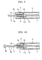
- the outer circumferential surface of the first electrode section 6 insulative by extending the insertion section 5 even further to the distal end side and configuring it so that it covers the outer circumferential surface, as shown in Fig. 9.
- the first electrode section is formed into a pipe shape with a circular section having a distal end surface in the above embodiments, the shape thereof is not limited to this.
- the distal end side can also be formed in a spherical shape, as shown in Fig. 10.
- the second electrode section is formed in a shape with a salient at the distal end thereof or in a needle shape
- the shape thereof is not limited to these.
- the shape can also be one with a bent section 9c whose distal end is bent by about 90 degrees, as shown in Fig. 11.
- the insulating member is arranged in the inner circumferential surface and proximal end surface of the first electrode section and the stopper member is made to provide insulation to the first electrode section when the second electrode section protrudes
- the invention is not limited to this form.
- stopper member and the first electrode section are electrically connected using a coil in the second embodiment
- other materials can be used.
Landscapes
- Health & Medical Sciences (AREA)
- Life Sciences & Earth Sciences (AREA)
- Surgery (AREA)
- Engineering & Computer Science (AREA)
- Plasma & Fusion (AREA)
- Medical Informatics (AREA)
- Otolaryngology (AREA)
- Physics & Mathematics (AREA)
- Cardiology (AREA)
- Biomedical Technology (AREA)
- Heart & Thoracic Surgery (AREA)
- Nuclear Medicine, Radiotherapy & Molecular Imaging (AREA)
- Molecular Biology (AREA)
- Animal Behavior & Ethology (AREA)
- General Health & Medical Sciences (AREA)
- Public Health (AREA)
- Veterinary Medicine (AREA)
- Surgical Instruments (AREA)
- Endoscopes (AREA)
Applications Claiming Priority (1)
| Application Number | Priority Date | Filing Date | Title |
|---|---|---|---|
| JP2005157050A JP4643361B2 (ja) | 2005-05-30 | 2005-05-30 | 内視鏡用処置具及び内視鏡用処置具システム |
Publications (3)
| Publication Number | Publication Date |
|---|---|
| EP1728462A2 true EP1728462A2 (de) | 2006-12-06 |
| EP1728462A3 EP1728462A3 (de) | 2007-05-30 |
| EP1728462B1 EP1728462B1 (de) | 2008-12-17 |
Family
ID=36968961
Family Applications (1)
| Application Number | Title | Priority Date | Filing Date |
|---|---|---|---|
| EP06010911A Active EP1728462B1 (de) | 2005-05-30 | 2006-05-26 | Instrument für Endoscope und Instrumentsystem für Endoscope. |
Country Status (4)
| Country | Link |
|---|---|
| US (1) | US7731714B2 (de) |
| EP (1) | EP1728462B1 (de) |
| JP (1) | JP4643361B2 (de) |
| DE (1) | DE602006004251D1 (de) |
Cited By (15)
| Publication number | Priority date | Publication date | Assignee | Title |
|---|---|---|---|---|
| EP1884214A1 (de) * | 2006-07-31 | 2008-02-06 | Fujinon Corporation | Elektrochirurgische Behandlungsvorrichtung |
| CN100459947C (zh) * | 2007-03-09 | 2009-02-11 | 中国人民解放军第三军医大学第一附属医院 | 无血切肝刀 |
| US20090326319A1 (en) * | 2007-03-02 | 2009-12-31 | Olympus Medical Systems Corp. | Endoscope apparatus |
| CN102204843A (zh) * | 2010-03-31 | 2011-10-05 | 富士胶片株式会社 | 内窥镜式高频治疗装置 |
| EP2322109A4 (de) * | 2008-08-13 | 2013-05-01 | Olympus Medical Systems Corp | Endoskop-behandlungsinstrument |
| EP2910212A4 (de) * | 2012-10-17 | 2016-06-22 | Olympus Corp | Hochfrequenzmesser |
| WO2016109907A1 (zh) * | 2015-01-05 | 2016-07-14 | 张建国 | 黏膜剥离器 |
| EP3187137A4 (de) * | 2014-08-06 | 2018-03-07 | Olympus Corporation | Hochfrequenzbehandlungsinstrument |
| WO2020226961A1 (en) * | 2019-05-06 | 2020-11-12 | Boston Scientific Scimed, Inc. | Medical device |
| US11083533B2 (en) | 2016-02-25 | 2021-08-10 | Olympus Corporation | Manipulator system and operating method thereof |
| WO2021231465A1 (en) | 2020-05-14 | 2021-11-18 | Singlepass Transseptal, Inc. | Transseptal crossing system for single pass large bore access |
| CN113677282A (zh) * | 2019-04-03 | 2021-11-19 | 奥林巴斯株式会社 | 透热内疗装置 |
| TWI759076B (zh) * | 2021-01-15 | 2022-03-21 | 陳映臻 | 治療內腔室傷口之藥劑推進裝置及其藥劑推進管 |
| US11298199B2 (en) | 2016-02-25 | 2022-04-12 | Olympus Corporation | Manipulator system and method for restricting a retreating motion of a manipulator according to a protrusion state of a manipulator joint |
| CN116531080A (zh) * | 2022-02-03 | 2023-08-04 | 奥林巴斯医疗株式会社 | 内窥镜用处置器具 |
Families Citing this family (63)
| Publication number | Priority date | Publication date | Assignee | Title |
|---|---|---|---|---|
| US8715281B2 (en) * | 2006-03-09 | 2014-05-06 | Olympus Medical Systems Corp. | Treatment device for endoscope |
| EP2049034B1 (de) | 2006-07-20 | 2012-01-11 | Boston Scientific Limited | Medizinische multifunktionsvorrichtung und verfahren zu ihrer verwendung |
| JP5048391B2 (ja) | 2007-04-27 | 2012-10-17 | 直久 矢作 | 内視鏡用処置具 |
| JP2008295905A (ja) * | 2007-06-04 | 2008-12-11 | Hoya Corp | 内視鏡用モノポーラ型高周波ナイフ |
| US8663221B2 (en) * | 2007-06-08 | 2014-03-04 | Olympus Medical Systems Corp. | Endoscopic treatment tool |
| JP2009090003A (ja) * | 2007-10-11 | 2009-04-30 | Fujinon Corp | 内視鏡用高周波処置具 |
| JP2009112788A (ja) * | 2007-10-17 | 2009-05-28 | Takashi Toyonaga | 高周波処置具 |
| US9125562B2 (en) | 2009-07-01 | 2015-09-08 | Avinger, Inc. | Catheter-based off-axis optical coherence tomography imaging system |
| US8062316B2 (en) * | 2008-04-23 | 2011-11-22 | Avinger, Inc. | Catheter system and method for boring through blocked vascular passages |
| JP5601776B2 (ja) * | 2009-02-09 | 2014-10-08 | Hoya株式会社 | 内視鏡用高周波処置具 |
| WO2010129075A1 (en) | 2009-04-28 | 2010-11-11 | Avinger, Inc. | Guidewire support catheter |
| WO2010138927A2 (en) | 2009-05-28 | 2010-12-02 | Avinger, Inc. | Optical coherence tomography for biological imaging |
| WO2011003006A2 (en) | 2009-07-01 | 2011-01-06 | Avinger, Inc. | Atherectomy catheter with laterally-displaceable tip |
| WO2011077850A1 (ja) * | 2009-12-22 | 2011-06-30 | オリンパスメディカルシステムズ株式会社 | 内視鏡用処置具 |
| US8465488B2 (en) | 2010-03-16 | 2013-06-18 | Olympus Medical Systems Corporation | Endoscopic surgical instrument |
| JP5864064B2 (ja) | 2010-06-15 | 2016-02-17 | アベヌ メディカル インコーポレイテッドAvenu Medical,Inc. | 動静脈(av)フィステルを作るためのシステムおよび方法 |
| WO2014039096A1 (en) | 2012-09-06 | 2014-03-13 | Avinger, Inc. | Re-entry stylet for catheter |
| EP2588012B1 (de) | 2010-07-01 | 2016-08-17 | Avinger, Inc. | Atherektomiekatheter mit länglich verschiebbaren antriebswellen |
| US11382653B2 (en) | 2010-07-01 | 2022-07-12 | Avinger, Inc. | Atherectomy catheter |
| EP2691038B1 (de) | 2011-03-28 | 2016-07-20 | Avinger, Inc. | Verstopfungsdurchquerungsvorrichtungen sowie bildgebungs- und atherektomievorrichtungen |
| US9949754B2 (en) | 2011-03-28 | 2018-04-24 | Avinger, Inc. | Occlusion-crossing devices |
| EP3653151A1 (de) | 2011-10-17 | 2020-05-20 | Avinger, Inc. | Atherektomiekatheter und kontaktloser antriebsmechanismus für katheter |
| US9345406B2 (en) | 2011-11-11 | 2016-05-24 | Avinger, Inc. | Occlusion-crossing devices, atherectomy devices, and imaging |
| JP5755121B2 (ja) * | 2011-11-30 | 2015-07-29 | Hoya株式会社 | 内視鏡用高周波処置具 |
| JP5884534B2 (ja) * | 2012-02-06 | 2016-03-15 | 住友ベークライト株式会社 | 高周波処置具 |
| WO2013172970A1 (en) | 2012-05-14 | 2013-11-21 | Avinger, Inc. | Atherectomy catheters with imaging |
| WO2013172974A1 (en) | 2012-05-14 | 2013-11-21 | Avinger, Inc. | Atherectomy catheter drive assemblies |
| WO2013172972A1 (en) | 2012-05-14 | 2013-11-21 | Avinger, Inc. | Optical coherence tomography with graded index fiber for biological imaging |
| US11284916B2 (en) | 2012-09-06 | 2022-03-29 | Avinger, Inc. | Atherectomy catheters and occlusion crossing devices |
| US9498247B2 (en) | 2014-02-06 | 2016-11-22 | Avinger, Inc. | Atherectomy catheters and occlusion crossing devices |
| EP2892448B1 (de) | 2012-09-06 | 2020-07-15 | Avinger, Inc. | Ballonatherektomiekatheter mit bildgebung |
| WO2014143064A1 (en) | 2013-03-15 | 2014-09-18 | Avinger, Inc. | Chronic total occlusion crossing devices with imaging |
| US11096717B2 (en) | 2013-03-15 | 2021-08-24 | Avinger, Inc. | Tissue collection device for catheter |
| US10932670B2 (en) | 2013-03-15 | 2021-03-02 | Avinger, Inc. | Optical pressure sensor assembly |
| JP6517198B2 (ja) | 2013-07-08 | 2019-05-22 | アビンガー・インコーポレイテッドAvinger, Inc. | 介入療法を案内する弾性層の識別 |
| JP5801022B1 (ja) * | 2014-01-14 | 2015-10-28 | オリンパス株式会社 | 切開具 |
| JP6539669B2 (ja) | 2014-02-06 | 2019-07-03 | アビンガー・インコーポレイテッドAvinger, Inc. | 粥腫切除カテーテル及び閉塞横断装置 |
| US9613729B2 (en) | 2014-05-20 | 2017-04-04 | Uchicago Argonne Llc | Mechanical design of multiple zone plates precision alignment apparatus for hard X-ray focusing in twenty-nanometer scale |
| MX2017000303A (es) | 2014-07-08 | 2017-07-10 | Avinger Inc | Dispositivos para oclusion transversal cronica total de alta velocidad. |
| EP3335656B1 (de) * | 2014-08-20 | 2019-06-12 | Gyrus ACMI, Inc. d/b/a/ Olympus Surgical Technologies America | Elektrochirurgische kombinationsvorrichtung mit mehreren modi |
| US10076381B2 (en) | 2014-09-08 | 2018-09-18 | Olympus Corporation | Method of marking lesion in tubular organ of an object |
| EP3322338B1 (de) | 2015-07-13 | 2025-02-12 | Avinger, Inc. | Mikrogeformte anamorphotische reflektorlinse für bildgeführte therapeutische/diagnosekatheter |
| CN108882857A (zh) | 2016-01-25 | 2018-11-23 | 阿维格公司 | 具有滞后修正的oct成像导管 |
| JP6959255B2 (ja) | 2016-04-01 | 2021-11-02 | アビンガー・インコーポレイテッドAvinger, Inc. | 粥腫切除用カテーテルデバイス |
| US11344327B2 (en) | 2016-06-03 | 2022-05-31 | Avinger, Inc. | Catheter device with detachable distal end |
| US11224459B2 (en) | 2016-06-30 | 2022-01-18 | Avinger, Inc. | Atherectomy catheter with shapeable distal tip |
| CN106214247B (zh) * | 2016-07-04 | 2018-08-14 | 南京微创医学科技股份有限公司 | 一种双极高频电刀 |
| CN107212920A (zh) * | 2017-01-23 | 2017-09-29 | 杭州安杰思医学科技有限公司 | 内窥镜用处理装置、内窥镜、及扩展支架 |
| KR102026938B1 (ko) * | 2017-06-13 | 2019-09-30 | 주식회사 파인메딕스 | 내시경용 하이브리드 나이프 |
| CN108272503B (zh) * | 2018-03-07 | 2024-04-19 | 南微医学科技股份有限公司 | 一种可双通道注液的双极高频电刀 |
| US12167867B2 (en) | 2018-04-19 | 2024-12-17 | Avinger, Inc. | Occlusion-crossing devices |
| US11083871B2 (en) * | 2018-05-03 | 2021-08-10 | Thermedical, Inc. | Selectively deployable catheter ablation devices |
| US12144536B2 (en) * | 2019-03-22 | 2024-11-19 | Kaneka Corporation | Endoscopic treatment instrument |
| JP2022553223A (ja) | 2019-10-18 | 2022-12-22 | アビンガー・インコーポレイテッド | 閉塞横断装置 |
| US20220087733A1 (en) * | 2020-09-23 | 2022-03-24 | Baylis Medical Company Inc. | Elongated medical needle |
| JP7757626B2 (ja) * | 2021-04-28 | 2025-10-22 | 住友ベークライト株式会社 | 内視鏡用針状メス |
| CN113598933B (zh) * | 2021-08-26 | 2024-10-18 | 南微医学科技股份有限公司 | 定位结构及装配方法、刀具及内窥镜系统 |
| CN116531082A (zh) * | 2022-03-31 | 2023-08-04 | 杭州安杰思医学科技股份有限公司 | 一种内窥镜及其前端盖 |
| JP2024004890A (ja) * | 2022-06-29 | 2024-01-17 | 富士フイルム株式会社 | 内視鏡用処置具及び送水部材 |
| DE102023134672A1 (de) * | 2022-12-14 | 2024-06-20 | Olympus Medical Systems Corp. | Endoskopisches behandlungswerkzeug |
| JP7744036B2 (ja) * | 2023-09-29 | 2025-09-25 | 株式会社 コスミック エム イー | プローブ、電気メス、ロボットハンド、ロボットアーム、及びロボット |
| CN120643260A (zh) * | 2024-03-13 | 2025-09-16 | 奥林巴斯医疗株式会社 | 内窥镜用处置器具 |
| WO2025262537A1 (en) * | 2024-06-18 | 2025-12-26 | Boston Scientific Medical Device Limited | Medical systems, devices, and related methods for applying energy, delivering fluid, and/or manipulating tissue |
Citations (2)
| Publication number | Priority date | Publication date | Assignee | Title |
|---|---|---|---|---|
| JPS55125858A (en) | 1979-03-19 | 1980-09-29 | Olympus Optical Co | Electric rod for erasion |
| JPH05337130A (ja) | 1992-03-23 | 1993-12-21 | Everest Medical Corp | 凝固電極付単極ポリープ切除係蹄 |
Family Cites Families (8)
| Publication number | Priority date | Publication date | Assignee | Title |
|---|---|---|---|---|
| US4682596A (en) * | 1984-05-22 | 1987-07-28 | Cordis Corporation | Electrosurgical catheter and method for vascular applications |
| US4708137A (en) * | 1985-05-20 | 1987-11-24 | Olympus Optical Co., Ltd. | High-frequency incision device |
| DE4323585A1 (de) * | 1993-07-14 | 1995-01-19 | Delma Elektro Med App | Bipolares Hochfrequenz-Chirurgieinstrument |
| US6056744A (en) * | 1994-06-24 | 2000-05-02 | Conway Stuart Medical, Inc. | Sphincter treatment apparatus |
| JP2002301088A (ja) * | 2001-04-05 | 2002-10-15 | Olympus Optical Co Ltd | 内視鏡用治療装置 |
| JP4109092B2 (ja) * | 2002-11-21 | 2008-06-25 | オリンパス株式会社 | 高周波ナイフ |
| JP4315725B2 (ja) * | 2003-04-17 | 2009-08-19 | オリンパス株式会社 | 高周波ナイフ |
| DE10327237A1 (de) * | 2003-06-17 | 2005-01-13 | Trumpf Medizin Systeme Gmbh + Co. Kg | Elektrochirurgisches Instrument für ein Endoskop |
-
2005
- 2005-05-30 JP JP2005157050A patent/JP4643361B2/ja not_active Expired - Fee Related
-
2006
- 2006-05-26 DE DE602006004251T patent/DE602006004251D1/de active Active
- 2006-05-26 EP EP06010911A patent/EP1728462B1/de active Active
- 2006-05-26 US US11/441,731 patent/US7731714B2/en active Active
Patent Citations (2)
| Publication number | Priority date | Publication date | Assignee | Title |
|---|---|---|---|---|
| JPS55125858A (en) | 1979-03-19 | 1980-09-29 | Olympus Optical Co | Electric rod for erasion |
| JPH05337130A (ja) | 1992-03-23 | 1993-12-21 | Everest Medical Corp | 凝固電極付単極ポリープ切除係蹄 |
Cited By (31)
| Publication number | Priority date | Publication date | Assignee | Title |
|---|---|---|---|---|
| EP1884214A1 (de) * | 2006-07-31 | 2008-02-06 | Fujinon Corporation | Elektrochirurgische Behandlungsvorrichtung |
| US20090326319A1 (en) * | 2007-03-02 | 2009-12-31 | Olympus Medical Systems Corp. | Endoscope apparatus |
| US9101339B2 (en) * | 2007-03-02 | 2015-08-11 | Olympus Corporation | Endoscope apparatus |
| EP2116174A4 (de) * | 2007-03-02 | 2016-12-21 | Olympus Corp | Endoskopvorrichtung |
| CN100459947C (zh) * | 2007-03-09 | 2009-02-11 | 中国人民解放军第三军医大学第一附属医院 | 无血切肝刀 |
| EP3799816A1 (de) * | 2008-08-13 | 2021-04-07 | Olympus Corporation | Behandlungsinstrument für endoskop |
| EP2322109A4 (de) * | 2008-08-13 | 2013-05-01 | Olympus Medical Systems Corp | Endoskop-behandlungsinstrument |
| EP4212119A1 (de) * | 2008-08-13 | 2023-07-19 | Olympus Corporation | Endoskopisches behandlungswerkzeug |
| EP4005517A1 (de) * | 2008-08-13 | 2022-06-01 | Olympus Corporation | Endoskopisches behandlungswerkzeug |
| CN102204843A (zh) * | 2010-03-31 | 2011-10-05 | 富士胶片株式会社 | 内窥镜式高频治疗装置 |
| US9387034B2 (en) | 2012-10-17 | 2016-07-12 | Olympus Corporation | High-frequency knife |
| EP2910212A4 (de) * | 2012-10-17 | 2016-06-22 | Olympus Corp | Hochfrequenzmesser |
| EP3187137A4 (de) * | 2014-08-06 | 2018-03-07 | Olympus Corporation | Hochfrequenzbehandlungsinstrument |
| WO2016109907A1 (zh) * | 2015-01-05 | 2016-07-14 | 张建国 | 黏膜剥离器 |
| US11298199B2 (en) | 2016-02-25 | 2022-04-12 | Olympus Corporation | Manipulator system and method for restricting a retreating motion of a manipulator according to a protrusion state of a manipulator joint |
| US11083533B2 (en) | 2016-02-25 | 2021-08-10 | Olympus Corporation | Manipulator system and operating method thereof |
| CN113677282B (zh) * | 2019-04-03 | 2024-04-12 | 奥林巴斯株式会社 | 透热内疗装置 |
| CN113677282A (zh) * | 2019-04-03 | 2021-11-19 | 奥林巴斯株式会社 | 透热内疗装置 |
| CN113840576A (zh) * | 2019-05-06 | 2021-12-24 | 波士顿科学国际有限公司 | 医疗装置 |
| US11564739B2 (en) | 2019-05-06 | 2023-01-31 | Boston Scientific Scimed, Inc. | Medical systems, devices, and related methods |
| WO2020226961A1 (en) * | 2019-05-06 | 2020-11-12 | Boston Scientific Scimed, Inc. | Medical device |
| EP4321105A3 (de) * | 2019-05-06 | 2024-02-21 | Boston Scientific Scimed, Inc. | Medizinische systeme, vorrichtungen und zugehörige verfahren |
| CN113840576B (zh) * | 2019-05-06 | 2025-01-07 | 波士顿科学国际有限公司 | 医疗装置 |
| EP4659692A3 (de) * | 2019-05-06 | 2026-01-14 | Boston Scientific Scimed, Inc. | Medizinische systeme, vorrichtungen und zugehörige verfahren |
| US12594117B2 (en) | 2019-05-06 | 2026-04-07 | Boston Scientific Scimed, Inc. | Medical systems, devices, and related methods |
| WO2021231465A1 (en) | 2020-05-14 | 2021-11-18 | Singlepass Transseptal, Inc. | Transseptal crossing system for single pass large bore access |
| EP4149378A4 (de) * | 2020-05-14 | 2024-05-29 | Circa Scientific, Inc. | Transseptales kreuzsystem für grossbohrzugang mit einem durchgang |
| US12213727B2 (en) | 2020-05-14 | 2025-02-04 | Circa Scientific, Inc. | Method for single pass large bore transseptal crossing |
| US12558152B2 (en) | 2020-05-14 | 2026-02-24 | Circa Scientific, Inc. | Transseptal crossing system for single pass large bore access |
| TWI759076B (zh) * | 2021-01-15 | 2022-03-21 | 陳映臻 | 治療內腔室傷口之藥劑推進裝置及其藥劑推進管 |
| CN116531080A (zh) * | 2022-02-03 | 2023-08-04 | 奥林巴斯医疗株式会社 | 内窥镜用处置器具 |
Also Published As
| Publication number | Publication date |
|---|---|
| US20060276784A1 (en) | 2006-12-07 |
| DE602006004251D1 (de) | 2009-01-29 |
| US7731714B2 (en) | 2010-06-08 |
| JP4643361B2 (ja) | 2011-03-02 |
| EP1728462A3 (de) | 2007-05-30 |
| EP1728462B1 (de) | 2008-12-17 |
| JP2006326157A (ja) | 2006-12-07 |
Similar Documents
| Publication | Publication Date | Title |
|---|---|---|
| EP1728462B1 (de) | Instrument für Endoscope und Instrumentsystem für Endoscope. | |
| CN109394306B (zh) | 具有组织止挡件的钳 | |
| EP1875876B1 (de) | Endoskopisches Behandlungsinstrument | |
| US5158561A (en) | Monopolar polypectomy snare with coagulation electrode | |
| US5197964A (en) | Bipolar instrument utilizing one stationary electrode and one movable electrode | |
| US6808525B2 (en) | Bipolar electrosurgical hook probe for cutting and coagulating tissue | |
| JP5636449B2 (ja) | 高周波処置具 | |
| KR100595803B1 (ko) | 고주파 나이프 및 내시경 장치 | |
| US7371236B2 (en) | Diathermic cutter | |
| EP2548527B1 (de) | Endoskopische behandlungsvorrichtung | |
| US6346106B1 (en) | Instrument and method employing snare electrode windable about rotatable spool for minimally invasive electrosurgical resection | |
| JP2009247696A (ja) | 高周波処置具 | |
| JPH0630947A (ja) | 外科器具 | |
| US8226646B2 (en) | High frequency treatment instrument | |
| CN110693604A (zh) | 内窥镜及扩展支架 | |
| EP2371315A1 (de) | Endoskopisches Hochfrequenz-Behandlungsinstrument | |
| EP3236869B1 (de) | Elektrochirugische schlinge mit variabler dicke | |
| US8298231B2 (en) | Bipolar scissors for adenoid and tonsil removal | |
| US20050240177A1 (en) | Electrosurgical forceps | |
| WO2022157977A1 (ja) | 処置具 | |
| JP7459311B2 (ja) | 処置具 | |
| JP7599673B2 (ja) | 腹腔鏡電気外科用装置 | |
| US20250228609A1 (en) | Endoscope treatment tool | |
| KR20250171334A (ko) | 에너지 및/또는 유체를 전달하기 위한 의료 디바이스 및 관련 방법 | |
| JP2023113571A (ja) | 内視鏡用処置具 |
Legal Events
| Date | Code | Title | Description |
|---|---|---|---|
| PUAI | Public reference made under article 153(3) epc to a published international application that has entered the european phase |
Free format text: ORIGINAL CODE: 0009012 |
|
| AK | Designated contracting states |
Kind code of ref document: A2 Designated state(s): AT BE BG CH CY CZ DE DK EE ES FI FR GB GR HU IE IS IT LI LT LU LV MC NL PL PT RO SE SI SK TR |
|
| AX | Request for extension of the european patent |
Extension state: AL BA HR MK YU |
|
| PUAL | Search report despatched |
Free format text: ORIGINAL CODE: 0009013 |
|
| AK | Designated contracting states |
Kind code of ref document: A3 Designated state(s): AT BE BG CH CY CZ DE DK EE ES FI FR GB GR HU IE IS IT LI LT LU LV MC NL PL PT RO SE SI SK TR |
|
| AX | Request for extension of the european patent |
Extension state: AL BA HR MK YU |
|
| RIC1 | Information provided on ipc code assigned before grant |
Ipc: A61B 1/018 20060101ALI20070420BHEP Ipc: A61B 18/14 20060101ALI20070420BHEP Ipc: A61B 18/00 20060101ALN20060925BHEP Ipc: A61B 1/00 20060101AFI20060925BHEP Ipc: A61B 17/32 20060101ALI20070420BHEP |
|
| 17P | Request for examination filed |
Effective date: 20070726 |
|
| 17Q | First examination report despatched |
Effective date: 20070831 |
|
| AKX | Designation fees paid |
Designated state(s): DE FR GB IE |
|
| GRAP | Despatch of communication of intention to grant a patent |
Free format text: ORIGINAL CODE: EPIDOSNIGR1 |
|
| GRAS | Grant fee paid |
Free format text: ORIGINAL CODE: EPIDOSNIGR3 |
|
| GRAA | (expected) grant |
Free format text: ORIGINAL CODE: 0009210 |
|
| AK | Designated contracting states |
Kind code of ref document: B1 Designated state(s): DE FR GB IE |
|
| REG | Reference to a national code |
Ref country code: GB Ref legal event code: FG4D |
|
| REG | Reference to a national code |
Ref country code: IE Ref legal event code: FG4D |
|
| REF | Corresponds to: |
Ref document number: 602006004251 Country of ref document: DE Date of ref document: 20090129 Kind code of ref document: P |
|
| PLBE | No opposition filed within time limit |
Free format text: ORIGINAL CODE: 0009261 |
|
| STAA | Information on the status of an ep patent application or granted ep patent |
Free format text: STATUS: NO OPPOSITION FILED WITHIN TIME LIMIT |
|
| 26N | No opposition filed |
Effective date: 20090918 |
|
| PGFP | Annual fee paid to national office [announced via postgrant information from national office to epo] |
Ref country code: IE Payment date: 20130517 Year of fee payment: 8 |
|
| PGFP | Annual fee paid to national office [announced via postgrant information from national office to epo] |
Ref country code: GB Payment date: 20140521 Year of fee payment: 9 |
|
| PGFP | Annual fee paid to national office [announced via postgrant information from national office to epo] |
Ref country code: FR Payment date: 20140509 Year of fee payment: 9 |
|
| REG | Reference to a national code |
Ref country code: IE Ref legal event code: MM4A |
|
| PG25 | Lapsed in a contracting state [announced via postgrant information from national office to epo] |
Ref country code: IE Free format text: LAPSE BECAUSE OF NON-PAYMENT OF DUE FEES Effective date: 20140526 |
|
| GBPC | Gb: european patent ceased through non-payment of renewal fee |
Effective date: 20150526 |
|
| REG | Reference to a national code |
Ref country code: FR Ref legal event code: ST Effective date: 20160129 |
|
| PG25 | Lapsed in a contracting state [announced via postgrant information from national office to epo] |
Ref country code: GB Free format text: LAPSE BECAUSE OF NON-PAYMENT OF DUE FEES Effective date: 20150526 |
|
| PG25 | Lapsed in a contracting state [announced via postgrant information from national office to epo] |
Ref country code: FR Free format text: LAPSE BECAUSE OF NON-PAYMENT OF DUE FEES Effective date: 20150601 |
|
| P01 | Opt-out of the competence of the unified patent court (upc) registered |
Effective date: 20230528 |
|
| PGFP | Annual fee paid to national office [announced via postgrant information from national office to epo] |
Ref country code: DE Payment date: 20250521 Year of fee payment: 20 |