EP1728463A1 - Systèmes d'endoscope - Google Patents
Systèmes d'endoscope Download PDFInfo
- Publication number
- EP1728463A1 EP1728463A1 EP06011509A EP06011509A EP1728463A1 EP 1728463 A1 EP1728463 A1 EP 1728463A1 EP 06011509 A EP06011509 A EP 06011509A EP 06011509 A EP06011509 A EP 06011509A EP 1728463 A1 EP1728463 A1 EP 1728463A1
- Authority
- EP
- European Patent Office
- Prior art keywords
- image
- endoscope system
- processor
- processors
- ultrasonic
- Prior art date
- Legal status (The legal status is an assumption and is not a legal conclusion. Google has not performed a legal analysis and makes no representation as to the accuracy of the status listed.)
- Granted
Links
- 230000002093 peripheral effect Effects 0.000 claims abstract description 95
- 230000003287 optical effect Effects 0.000 claims description 12
- 239000002131 composite material Substances 0.000 claims description 11
- 238000003384 imaging method Methods 0.000 claims description 9
- 230000001427 coherent effect Effects 0.000 claims description 5
- 238000003745 diagnosis Methods 0.000 claims description 5
- 238000003325 tomography Methods 0.000 claims description 2
- 238000010586 diagram Methods 0.000 description 5
- 230000006870 function Effects 0.000 description 4
- 238000012327 Endoscopic diagnosis Methods 0.000 description 3
- 238000009434 installation Methods 0.000 description 3
- 239000000523 sample Substances 0.000 description 3
- 101100004933 Arabidopsis thaliana CYP79F1 gene Proteins 0.000 description 1
- 230000000694 effects Effects 0.000 description 1
- 238000012986 modification Methods 0.000 description 1
- 230000004048 modification Effects 0.000 description 1
- 230000000007 visual effect Effects 0.000 description 1
Images






Classifications
-
- A—HUMAN NECESSITIES
- A61—MEDICAL OR VETERINARY SCIENCE; HYGIENE
- A61B—DIAGNOSIS; SURGERY; IDENTIFICATION
- A61B8/00—Diagnosis using ultrasonic, sonic or infrasonic waves
- A61B8/12—Diagnosis using ultrasonic, sonic or infrasonic waves in body cavities or body tracts, e.g. by using catheters
-
- A—HUMAN NECESSITIES
- A61—MEDICAL OR VETERINARY SCIENCE; HYGIENE
- A61B—DIAGNOSIS; SURGERY; IDENTIFICATION
- A61B1/00—Instruments for performing medical examinations of the interior of cavities or tubes of the body by visual or photographical inspection, e.g. endoscopes; Illuminating arrangements therefor
- A61B1/012—Instruments for performing medical examinations of the interior of cavities or tubes of the body by visual or photographical inspection, e.g. endoscopes; Illuminating arrangements therefor characterised by internal passages or accessories therefor
-
- A—HUMAN NECESSITIES
- A61—MEDICAL OR VETERINARY SCIENCE; HYGIENE
- A61B—DIAGNOSIS; SURGERY; IDENTIFICATION
- A61B1/00—Instruments for performing medical examinations of the interior of cavities or tubes of the body by visual or photographical inspection, e.g. endoscopes; Illuminating arrangements therefor
- A61B1/04—Instruments for performing medical examinations of the interior of cavities or tubes of the body by visual or photographical inspection, e.g. endoscopes; Illuminating arrangements therefor combined with photographic or television appliances
- A61B1/042—Instruments for performing medical examinations of the interior of cavities or tubes of the body by visual or photographical inspection, e.g. endoscopes; Illuminating arrangements therefor combined with photographic or television appliances characterised by a proximal camera, e.g. a CCD camera
Definitions
- the present invention relates to an ultrasonic endoscope system that takes endoscopic images and ultrasonographic images using an ultrasonic endoscope.
- the present invention also relates to an electronic endoscope system that takes endoscopic images using an electronic endoscope.
- the endoscope has an imaging device, such as a CCD, at its end, for capturing an optical image of a certain part inside a living body, to take an endoscopic image.
- Some endoscope is provided with an ultrasonic transducer that projects ultrasonic waves toward a certain internal body part, and receives echo signals from the internal body part, to take an ultrasonographic image, so that ultrasonic diagnosis can be made simultaneously with endoscopic diagnosis.
- one has a treatment tool introduction channel for introducing an ultrasonic probe having an ultrasonic transducer at its end, and another has an ultrasonic transducer disposed near an imaging device. The latter type is called an ultrasonic endoscope.
- a processor for endoscope and a processor for ultrasonograph have been necessary for producing an endoscopic image from the signal captured through the imaging device and for producing an ultrasonographic image from the echo signal.
- These processors have to be operated individually, and the endoscopic image and the ultrasonographic image are displayed and observed on individual monitors. Accordingly, the conventional system is disadvantageous in view of installation space efficiency and operability.
- Japanese Laid-open Patent Application No. Hei 11-309148 suggests an ultrasonic diagnostic apparatus that displays an endoscopic image and an ultrasonic image as a composite image, called a picture-in-picture display, on a common monitor.
- Japanese Laid-open Patent Application No. 2001-145627 suggests a medical image observer that has a common operational section for an endoscope and an ultrasonic transducer.
- a primary object of the present invention is to provide such an ultrasonic endoscope system and an electronic endoscope system, of which installation space is less restricted than conventional, and which are remarkably improved in operability.
- an ultrasonic endoscope system of the present invention comprises an ultrasonic endoscope having an end portion with an imaging device for capturing an optical image of a certain internal body part to output an image signal, and an ultrasonic transducer for emitting an ultrasonic wave toward the internal body part to receive an echo signal from the internal body part, an endoscope processor for producing an endoscopic image from the image signal, an ultrasonograph processor for producing an ultrasonographic image from the echo signal, and a plurality of peripheral equipments that exchange data with the processors, wherein the processors are connected to the peripheral equipments through serial buses having bus arbitration function.
- the ultrasonic endoscope system further comprises a peripheral equipment control unit that is connected to the processors and the peripheral equipments through the serial buses.
- the peripheral equipment control unit serves as an intermediary of data between the processors, on one hand, and the peripheral equipments, on the other hand.
- the serial buses connecting the peripheral equipment control unit to the processors and the peripheral equipments are preferably universal serial buses.
- the peripheral equipment control unit controls those of the universal serial buses which are connected respectively to the processors, independently from each other.
- the the peripheral equipment control unit comprises at least two USB controllers and a CPU for controlling operation of the USB controllers, and operates as a host while exchanging data with the peripheral equipments, and as a device while exchanging data with the processors.
- the peripheral equipments include a movie recorder for recording a selected one of the endoscopic image and the ultrasonographic image as a movie image.
- the peripheral equipments include a first operational device for selecting one of the endoscopic image and the ultrasonographic image, to be recorded by the movie recorder.
- the processors are preferably connected to the movie recorder through an IEEE1394 bus, wherein an output plug and an input plug of the IEEE1394 bus are established at a first one of the processors, a second output plug of the IEEE1394 bus is established at a second one of the processors, and a second input plug of the IEEE1394 bus is established at the movie recorder, and wherein a first isochronous channel is established between the first processor and the movie recorder, and a second isochronous channel is established between the first and second processors.
- the ultrasonic endoscope system further comprises an image composing device for composing the endoscopic image and the ultrasonographic image to produce a composite image, and an image display device for displaying a selected one of the endoscopic image, the ultrasonographic image and the composite image.
- An electronic endoscope system of the present invention comprises an electronic endoscope having an end portion with an imaging device for capturing an optical image of a certain internal body part to output an image signal, an endoscope processor for producing an endoscopic image from the image signal, and a plurality of peripheral equipments that exchange data with the processors wherein the endoscope processor is connected to the peripheral equipments through serial buses having bus arbitration function.
- a peripheral equipment control unit is connected to the endoscope processor and the peripheral equipments through the serial buses.
- the peripheral equipment control unit serves as an intermediary of data between the endoscope processor and the peripheral equipments, wherein the peripheral equipments preferably include at least a second processor that produces from an electric signal an image served for medical diagnosis, such as an ultrasonographic image or an optical coherent tomographic image.
- the endoscope processor and the ultrasonograph processor or other kinds of processors can share the same peripheral equipments. Because the processors are connected to the peripheral equipments through the serial buses having bus arbitration function, wiring is simplified in comparison with a conventional system that adopts RS232C-connection or PS/2-connection.
- an ultrasonic endoscope system 2 of the present invention consists of an ultrasonic endoscope 10 and an observation device 11.
- the ultrasonic endoscope 10 has a CCD 12 and an ultrasonic transducer 13 incorporated therein, wherein the CCD 12 captures an optical image of a certain internal body part to output an image signal, and the ultrasonic transducer 13 emits ultrasonic waves toward the certain internal body part and receives an echo signal from the certain internal body part.
- the observation device 11 is mainly constituted of an endoscope processor 14, an ultrasonograph processor 15 and a peripheral equipment control unit 16.
- the endoscope processor 14 is connected to the CCD 12, to control driving the CCD 12, produce an endoscopic image from the image signal entered by the CCD 12, and output digital data of the endoscopic image to a monitor for endoscopic image 17.
- the endoscopic image monitor 17 is connected to the endoscope processor 14 through DVI (digital visual interface).
- the ultrasonograph processor 15 is connected to the ultrasonic transducer 13, to control driving the ultrasonic transducer 13, produce an ultrasonographic image from the echo signal entered by the ultrasonic transducer 13, and outputs digital data of the ultrasonographic image to a monitor for ultrasonographic image 18.
- the ultrasonographic image monitor 18 is connected to the ultrasonograph processor 15 through the DVI.
- the peripheral equipment control unit 16 is connected to the respective processors 14 and 15 and peripheral equipments 19 through USB (universal serial bus) connections.
- the peripheral equipments 19 include a printer 20 for printing out the endoscopic image or the ultrasonographic image, and a driver 21 for reading and writing data between the peripheral equipment control unit 16 and external storage media, such as floppy disc (trade name), MO, CD-ROM, DVD-ROM and flash memory.
- the peripheral equipments 19 further include a keyboard 22, a footswitch 23 and a card reader 24 for reading data out of a memory card that stores personal data of a patient, such as the name and the sex of the patient.
- the peripheral equipment control unit 16 consists of a CPU 30 and first to third USB controllers 31, 32 and 33, which operate under the control of the CPU 30.
- the first to third USB controllers 31 to 33 are connected to the endoscope processor 14, the ultrasonograph processor 15 and the peripheral equipments 19 respectively.
- the third USB controller 33 has a switching hub function.
- the respective processors 14 and 15 and the peripheral equipments 19 operate as hosts and devices to the peripheral equipment control unit 16.
- the peripheral equipment control unit 16 operates as a host while exchanging data with the peripheral equipments 19 through a bus BUS1, and also operates as a device while exchanging data with the respective processors 14 and 15 through individual buses BUS2 and BUS3.
- the CPU 30 switches the peripheral equipment control unit 16 between the host operation and the device operation.
- the respective processors 14 and 15 are connected to a filing device 25 and a movie recorder 26.
- the filing device 25 is connected to the respective processors 14 and 15 through Ethernet (trade name) as show by dashed line in Fig.1.
- the filing device 25 obtains the endoscopic image and the ultrasonographic image from the respective processors 14 and 15 through the Ethernet, to record them as image files.
- the movie recorder 26 is connected to the respective processors 14 and 15 through IEEE1394 bus as shown by chain-dotted lines in Fig.1.
- the movie recorder 26 obtains the endoscopic image and the ultrasonographic image from the respective processors 14 and 15 through the IEEE1394 bus, to record them digitally on a recording medium, like a recording tape.
- an output plug P (point to point out) and an input plug B (broadcast in) of the IEEE1394 bus are established at the ultrasonograph processor 15, whereas an output plug B (broadcast out) of the IEEE1394 bus is established at the endoscope processor 14, and an input plug P (point to point in) of the IEEE1394 bus is established at the movie recorder 26.
- a first isochronous channel X is established between the ultrasonograph processor 15 and the movie recorder 26
- a second isochronous channel Y is established between the endoscope processor 14 and the ultrasonograph processor 15.
- the keyboard 22 is provided with an endoscopic image recording switch 40, an ultrasonographic image recording switch 41 and a recording priority selection switch 42.
- the endoscopic image recording switch 40 is operated to record the endoscopic image as a movie image by the movie recorder 26, whereas the ultrasonographic image recording switch 41 is operated to record the ultrasonographic image as a movie image by the movie recorder 26.
- the recording priority selection switch 42 is operated to choose between an endoscope priority mode for giving priority to the movie recording of the endoscopic image and an ultrasonograph priority mode for giving priority to the movie recording of the ultrasonographic image.
- OP and US stand for endoscopic image and ultrasonographic image respectively, and the same applies to Fig.12.
- the endoscope processor 14 controls the movie recorder 26 such that the movie recorder 26 alternately starts and stops the movie recording of the endoscopic image upon the endoscopic image recording switch 40 being operated.
- the ultrasonograph processor 15 controls the movie recorder 26 such that the movie recorder 26 alternately starts and stops the movie recording of the ultrasonographic image upon the ultrasonographic image recording switch 41 being operated.
- the respective processors 14 and 15 also control the movie recorder 26 to record either the endoscopic image or the ultrasonographic image, which is selected by the recording priority selection switch 42, prior to the recording as designated by the endoscopic image recording switch 40 or the ultrasonographic image recording switch 41.
- the CCD 12 When a command for obtaining an endoscopic image is entered while an inserting portion of the ultrasonic endoscope 10 is inserted in a living body, the CCD 12 captures an optical image of a certain part inside the living body and outputs an image signal. The image signal from the CCD 12 is fed to the endoscope processor 14.
- the endoscope processor 14 subjects the image signal to many kinds of image-processing to produce the endoscopic image.
- the endoscopic image produced through the endoscope processor 14 is displayed on the endoscopic image monitor 17.
- the ultrasonic transducer 13 While the endoscopic image is being observed on the endoscopic image monitor 17, a particular internal body part is searched.
- the ultrasonic transducer 13 emits the ultrasonic wave toward the particular body part.
- the particular body part reflects the echo signal in correspondence to the ultrasonic wave, so the ultrasonic transducer 13 receives the echo signal.
- the echo signal received on the ultrasonic transducer 13 is fed to the ultrasonograph processor 15.
- the ultrasonograph processor 15 subjects the echo signal to many kinds of image-processing to produce the ultrasonographic image.
- the ultrasonographic image produced through the ultrasonograph processor 15 is displayed on the ultrasonographic image monitor 18.
- the peripheral equipment control unit 16 when the peripheral equipment control unit 16 receives a print command for the printer 20 from the respective processors 14 and 15, the peripheral equipment control unit 16 operates as a device to the respective processors 14 and 15, on receiving data to print from the respective processors 14 and 15. Then, the peripheral equipment control unit 16 operates as a host to the printer 20, on sending the received data to the printer 20.
- peripheral equipment control unit 16 When the peripheral equipment control unit 16 receives a command for writing data on a storage medium from the respective processors 14 and 15, as shown in Fig. 7, the peripheral equipment control unit 16 operates as a device to the respective processors 14 and 15, on receiving the data to write. Then the peripheral equipment control unit 16 operates as a host to the driver 21, on sending the received data to the driver 21.
- the peripheral equipment control unit 16 operates as a device to the keyboard 22 or the footswitch 23, on receiving an operational signal from the keyboard 22 or the footswitch 23. Then the peripheral equipment control unit 16 operates as a host to the respective processors 14 and 15, on sending the received operational signal to the endoscope processor 14 or the ultrasonograph processor 15. In order to distinct the operational signal assigned to the endoscope processor 14 from one assigned to the ultrasonograph processor 15, a specific code is attached to the operational signal for the endoscope processor 14, so that the peripheral equipment control unit 16 checks the operational signal if the specific code is attached or not, to determine which of the processors 14 and 15 the operational signal should be sent to.
- peripheral equipment control unit 16 When the peripheral equipment control unit 16 reads data through the card reader 24, as shown in Fig.9, the peripheral equipment control unit 16 operates as a host to the card reader 24. Then, on sending the read data to the respective processors 14 and 15, the peripheral equipment control unit 16 operates as a device to the respective processors 14 and 15.
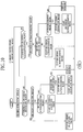
- the endoscope processor 14 checks the state of operation of the movie recorder 26. If the movie recorder 26 is already recording the endoscopic image, the endoscope processor 14 sends the movie recorder 26 a command for stopping recording the endoscopic image, so the movie recorder 26 stops the recording of the endoscopic image.
- the endoscope processor 14 sends the movie recorder 26 a command for starting recording the endoscopic image, so the movie recorder 26 stars recording the endoscopic image.
- the endoscope processor 14 sends the movie recorder 26 a command for stopping recording the ultrasonographic image. After the recording of the ultrasonographic image is stopped, the endoscope processor 14 sends the movie recorder 26 the command for starting recording the endoscopic image, so the movie recorder 26 stars recording the endoscopic image.
- the endoscope priority mode is not selected by the recording priority selection switch 42, a warning is displayed on the endoscopic image monitor 17.
- the operation of the ultrasonograph processor 15 responsive to an ultrasonographic image recording command which is entered through the ultrasonographic image recording switch 41, is the same as the above-described operation of the endoscope processor 14 responsive to the endoscopic image recording command, if only "the endoscopic image” is replaced with "the ultrasonographic image”. So the detailed description relating the ultrasonographic image recording command is omitted.
- the endoscope processor 14 and the ultrasonograph processor 15 are connected to the peripheral equipments 19 via the peripheral equipment control unit 16 by the USB connection, whereas the processors 14 and 15 are connected to the filing device 25 and the movie recorder 26 through the Ethernet and the IEEE1394 bus respectively. Accordingly, the endoscope processor 14 and the ultrasonograph processor 15 use the same peripheral equipments 19. Besides that, wiring between the equipments and the devices is simplified in comparison with a conventional ultrasonic endoscope system that adopts RS232C-connection or PS/2-connection.
- the system operator can record the image of the designated kind without fail.
- the peripheral equipment control unit 16 may be built in the endoscope processor 14. It is also possible to integrate the first or the second USB controller 31 or 32 with the third USB controller 33.
- the position of the endoscope processor 14 may be exchanged with the position of the ultrasonograph processor 15.
- the plugs of the second isochronous channel Y may be the point to point type.
- an ultrasonic endoscope system 50 is provided with an observer 52 having a common monitor 51 that displays an endoscopic image, an ultrasonic image or a composite image as set forth in detail later.
- the common monitor 51 is connected to an ultrasonograph processor 53.
- the ultrasonograph processor 53 is provided with an image composer circuit 54 for producing the composite image by composing the endoscopic image, which is sent from an endoscope processor 14 through an IEEE1394 bus, with the ultrasonographic image produced by the ultrasonograph processor 53.
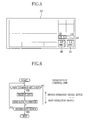
- the image composer 54 can change the ratio of an endoscopic image display area to an ultrasonographic image display area in the composite image on the screen of the common monitor 51. For example, as shown in Fig.13, the ratio may change in three steps of 4:1, 1:1 and 1:4.
- a keyboard 55 of the ultrasonic endoscope system 50 has a display mode switch 60 and a display mode dial 61 in addition to image recording switches 40 and 41 and a recording priority selection switch 42.
- the display mode dial 61 can work only while the display mode switch 60 is turned on. Concretely, it becomes possible to turn the display mode dial 61 when the display mode switch 60 is pressed down.
- the display mode on the common monitor 51 changes.
- USI represents the ultrasonographic image
- OPI represents the endoscopic image.
- Fig.14 shows an electronic endoscope system 70 of the present invention.
- the electronic endoscope system 70 consists of an electronic endoscope 71, an endoscope processor 73 that is connected to a CCD 72 of the electronic endoscope 71, and a peripheral equipment control unit 74 that is integrated in the endoscope processor 73.
- the endoscope processor 73 produces an endoscopic image from an image signal output from the CCD 72.
- the endoscope processor 73 is connected to a common monitor 75, a filing device 76 and a movie recorder 77 through the DVI connection, the Ethernet and the IEEE1394 bus, respectively.
- the peripheral equipment control unit 74 is connected to peripheral equipments 83, including a printer 78, a driver 79, a keyboard 80, a footswitch 81 and a card reader 82, through USB connections.
- the peripheral equipment control unit 74 is also connected to an ultrasonograph processor 86 and an OCT (optical coherent tomography) processor 89 through the USB connections.
- the ultrasonograph processor 86 is connected to an ultrasonic transducer 85 of an ultrasonic probe 84, to produce an ultrasonographic image from an echo signal received on the ultrasonic transducer 85.
- the OCT processor 89 is connected to an OCT element 88 of an OCT probe 87, to produce an optical coherent tomographic image.
- the ultrasonograph processor 86 and the OCT processor 89 are connected to the filing device 76 through the Ethernet, and to the movie recorder 77 through the IEEE1394 bus.
- the configuration shown in Fig.14 allows a plurality of medical equipments to share the peripheral equipments 83. Furthermore, because only the endoscope processor 73 has to be turned on for making the endoscopic diagnosis, this configuration contributes to reducing electric power consumption. Note that the peripheral equipment control unit 74 may be a separate body form the endoscope processor 73. It is possible to provide the keyboard 80 with image recording switches, a recording priority selection switch, a display mode switch and a display mode dial, like the embodiment shown in Fig.12, to get the same effects as above.
- connection between the processors and the monitors or the common monitor is not limited to the DVI, but the analog RGB format is usable. Also S-VIDEO format or VIDEO format may also be usable, though the image quality is inferior to the DVI and the analog RGB format.
- wired serial buses like the USB, the Ethernet and the IEEE1394 bus
- radio serial buses such as Bluetooth, IEEE801.11a/b/g.
Landscapes
- Health & Medical Sciences (AREA)
- Life Sciences & Earth Sciences (AREA)
- Surgery (AREA)
- General Health & Medical Sciences (AREA)
- Medical Informatics (AREA)
- Veterinary Medicine (AREA)
- Pathology (AREA)
- Radiology & Medical Imaging (AREA)
- Biophysics (AREA)
- Engineering & Computer Science (AREA)
- Biomedical Technology (AREA)
- Heart & Thoracic Surgery (AREA)
- Nuclear Medicine, Radiotherapy & Molecular Imaging (AREA)
- Molecular Biology (AREA)
- Animal Behavior & Ethology (AREA)
- Physics & Mathematics (AREA)
- Public Health (AREA)
- Optics & Photonics (AREA)
- Endoscopes (AREA)
- Ultra Sonic Daignosis Equipment (AREA)
Applications Claiming Priority (1)
| Application Number | Priority Date | Filing Date | Title |
|---|---|---|---|
| JP2005163110A JP4727302B2 (ja) | 2005-06-02 | 2005-06-02 | 超音波内視鏡システムおよび電子内視鏡システム |
Publications (2)
| Publication Number | Publication Date |
|---|---|
| EP1728463A1 true EP1728463A1 (fr) | 2006-12-06 |
| EP1728463B1 EP1728463B1 (fr) | 2012-01-25 |
Family
ID=36950014
Family Applications (1)
| Application Number | Title | Priority Date | Filing Date |
|---|---|---|---|
| EP06011509A Ceased EP1728463B1 (fr) | 2005-06-02 | 2006-06-02 | Systèmes d'endoscope |
Country Status (3)
| Country | Link |
|---|---|
| US (1) | US20060276687A1 (fr) |
| EP (1) | EP1728463B1 (fr) |
| JP (1) | JP4727302B2 (fr) |
Cited By (6)
| Publication number | Priority date | Publication date | Assignee | Title |
|---|---|---|---|---|
| EP1977695A1 (fr) * | 2007-04-04 | 2008-10-08 | Olympus Medical Systems Corporation | Système d'endoscope à ultrasons et procédé de contrôle de système d'endoscope à ultrasons |
| EP2168496A1 (fr) * | 2008-09-30 | 2010-03-31 | FUJIFILM Corporation | Sélecteur de signal vidéo et son système de remplissage d'image médicale |
| CN101273905B (zh) * | 2007-03-29 | 2010-12-22 | 奥林巴斯医疗株式会社 | 系统控制器 |
| WO2015013995A1 (fr) * | 2013-07-31 | 2015-02-05 | 深圳先进技术研究院 | Dispositif d'imagerie ultrasonore endoscopique et procédé destiné au cancer du nasopharynx |
| US9687211B2 (en) | 2013-10-01 | 2017-06-27 | Olympus Corporation | Ultrasound endoscope system and communication method of the ultrasound endoscope system |
| KR20240107504A (ko) * | 2022-12-30 | 2024-07-09 | 현대제철 주식회사 | 검사장치 및 그 제어방법 |
Families Citing this family (4)
| Publication number | Priority date | Publication date | Assignee | Title |
|---|---|---|---|---|
| JP5097565B2 (ja) * | 2008-01-24 | 2012-12-12 | 株式会社トプコン | 眼科撮影装置 |
| WO2011039955A1 (fr) * | 2009-09-30 | 2011-04-07 | テルモ株式会社 | Dispositif de diagnostic par imagerie |
| JP2012135509A (ja) * | 2010-12-27 | 2012-07-19 | Hoya Corp | 内視鏡装置 |
| CN103616763A (zh) * | 2013-12-06 | 2014-03-05 | 深圳市道通科技有限公司 | 工业内窥镜系统和利用该系统进行检测的方法 |
Citations (4)
| Publication number | Priority date | Publication date | Assignee | Title |
|---|---|---|---|---|
| US5868666A (en) * | 1993-11-26 | 1999-02-09 | Olympus Optical Co., Ltd. | Endoscope apparatus using programmable integrated circuit to constitute internal structure thereof |
| US6397286B1 (en) | 1997-03-12 | 2002-05-28 | Storz Endoskop Gmbh | Arrangement for the central monitoring and/or control of at least one apparatus |
| US20040141054A1 (en) * | 1999-06-09 | 2004-07-22 | Olympus Corporation | Image processing unit whose ability to process endoscopic image signal can be expanded, and endoscopic imaging system |
| WO2005120329A1 (fr) * | 2004-06-07 | 2005-12-22 | Medigus Ltd. | Equipement pour endoscopie a usages multiples |
Family Cites Families (16)
| Publication number | Priority date | Publication date | Assignee | Title |
|---|---|---|---|---|
| JPH04183446A (ja) * | 1990-11-19 | 1992-06-30 | Res Dev Corp Of Japan | 画像合成による手術支援システム |
| US5848969A (en) * | 1996-10-28 | 1998-12-15 | Ep Technologies, Inc. | Systems and methods for visualizing interior tissue regions using expandable imaging structures |
| US5971923A (en) * | 1997-12-31 | 1999-10-26 | Acuson Corporation | Ultrasound system and method for interfacing with peripherals |
| JP3892969B2 (ja) * | 1998-04-28 | 2007-03-14 | オリンパス株式会社 | 超音波診断装置 |
| JP2000245694A (ja) * | 1999-03-03 | 2000-09-12 | Olympus Optical Co Ltd | 内視鏡撮像装置 |
| JP2000325350A (ja) * | 1999-05-20 | 2000-11-28 | Olympus Optical Co Ltd | 超音波診断装置 |
| JP2002017729A (ja) * | 2000-07-11 | 2002-01-22 | Toshiba Corp | 超音波内視鏡診断装置 |
| JP2002345745A (ja) * | 2001-05-22 | 2002-12-03 | Olympus Optical Co Ltd | 内視鏡システム |
| JP3878456B2 (ja) * | 2001-11-14 | 2007-02-07 | ジーイー・メディカル・システムズ・グローバル・テクノロジー・カンパニー・エルエルシー | 画像診断支援システム |
| US7115093B2 (en) * | 2001-11-21 | 2006-10-03 | Ge Medical Systems Global Technology Company, Llc | Method and system for PDA-based ultrasound system |
| JP3878462B2 (ja) * | 2001-11-22 | 2007-02-07 | ジーイー・メディカル・システムズ・グローバル・テクノロジー・カンパニー・エルエルシー | 画像診断支援システム |
| ATE499880T1 (de) * | 2002-09-27 | 2011-03-15 | Olympus Corp | Ultraschalldiagnosevorrichtung |
| JP4618980B2 (ja) * | 2003-01-08 | 2011-01-26 | Hoya株式会社 | 電子内視鏡システム |
| JP2004343155A (ja) * | 2003-05-12 | 2004-12-02 | Olympus Corp | 映像信号処理装置 |
| JP2005095567A (ja) * | 2003-09-02 | 2005-04-14 | Olympus Corp | 内視鏡システム |
| TWI267744B (en) * | 2005-02-18 | 2006-12-01 | Uli Electronics Inc | Multi-standard display chipset architecture |
-
2005
- 2005-06-02 JP JP2005163110A patent/JP4727302B2/ja not_active Expired - Fee Related
-
2006
- 2006-06-02 EP EP06011509A patent/EP1728463B1/fr not_active Ceased
- 2006-06-02 US US11/445,343 patent/US20060276687A1/en not_active Abandoned
Patent Citations (4)
| Publication number | Priority date | Publication date | Assignee | Title |
|---|---|---|---|---|
| US5868666A (en) * | 1993-11-26 | 1999-02-09 | Olympus Optical Co., Ltd. | Endoscope apparatus using programmable integrated circuit to constitute internal structure thereof |
| US6397286B1 (en) | 1997-03-12 | 2002-05-28 | Storz Endoskop Gmbh | Arrangement for the central monitoring and/or control of at least one apparatus |
| US20040141054A1 (en) * | 1999-06-09 | 2004-07-22 | Olympus Corporation | Image processing unit whose ability to process endoscopic image signal can be expanded, and endoscopic imaging system |
| WO2005120329A1 (fr) * | 2004-06-07 | 2005-12-22 | Medigus Ltd. | Equipement pour endoscopie a usages multiples |
Cited By (8)
| Publication number | Priority date | Publication date | Assignee | Title |
|---|---|---|---|---|
| CN101273905B (zh) * | 2007-03-29 | 2010-12-22 | 奥林巴斯医疗株式会社 | 系统控制器 |
| EP1975826A3 (fr) * | 2007-03-29 | 2013-03-06 | Olympus Medical Systems Corp. | Contrôleur de système |
| EP1977695A1 (fr) * | 2007-04-04 | 2008-10-08 | Olympus Medical Systems Corporation | Système d'endoscope à ultrasons et procédé de contrôle de système d'endoscope à ultrasons |
| US8858426B2 (en) | 2007-04-04 | 2014-10-14 | Olympus Medical Systems Corp. | Ultrasound endoscope system and control method of ultrasound endoscope system |
| EP2168496A1 (fr) * | 2008-09-30 | 2010-03-31 | FUJIFILM Corporation | Sélecteur de signal vidéo et son système de remplissage d'image médicale |
| WO2015013995A1 (fr) * | 2013-07-31 | 2015-02-05 | 深圳先进技术研究院 | Dispositif d'imagerie ultrasonore endoscopique et procédé destiné au cancer du nasopharynx |
| US9687211B2 (en) | 2013-10-01 | 2017-06-27 | Olympus Corporation | Ultrasound endoscope system and communication method of the ultrasound endoscope system |
| KR20240107504A (ko) * | 2022-12-30 | 2024-07-09 | 현대제철 주식회사 | 검사장치 및 그 제어방법 |
Also Published As
| Publication number | Publication date |
|---|---|
| EP1728463B1 (fr) | 2012-01-25 |
| JP2006334169A (ja) | 2006-12-14 |
| US20060276687A1 (en) | 2006-12-07 |
| JP4727302B2 (ja) | 2011-07-20 |
Similar Documents
| Publication | Publication Date | Title |
|---|---|---|
| JP2940827B2 (ja) | 医療用画像ファイリング装置 | |
| JP4615204B2 (ja) | 電子内視鏡装置 | |
| JP2005110954A (ja) | 電子内視鏡装置 | |
| US8073211B2 (en) | Method and apparatus for generating variable resolution medical images | |
| EP1728463B1 (fr) | Systèmes d'endoscope | |
| JP2005130881A (ja) | 電子内視鏡装置 | |
| JP2008545449A (ja) | 内視鏡画像システム | |
| JPH05161641A (ja) | 超音波診断装置 | |
| JP2002534148A (ja) | 超音波視覚化システム | |
| US7585272B2 (en) | Electronic endoscope, and method for transferring programs | |
| JP2000325350A (ja) | 超音波診断装置 | |
| JP3325226B2 (ja) | 超音波診断装置 | |
| EP1977695B1 (fr) | Système d'endoscope à ultrasons et procédé de contrôle de système d'endoscope à ultrasons | |
| JP5075491B2 (ja) | 可搬型診断装置 | |
| JPH11275418A (ja) | プリンタ一体結合可能なデジタルカメラシステム | |
| CN219089211U (zh) | 兼容电子内窥镜和光学内窥镜的摄像装置 | |
| JPH07171115A (ja) | 画像診断装置 | |
| JP3483923B2 (ja) | 画像処理装置 | |
| JP2004194705A (ja) | 超音波診断システム及び超音波撮像条件設定方法 | |
| JP7447692B2 (ja) | 超音波診断装置、超音波診断装置の制御方法、及び、超音波診断装置の制御プログラム | |
| JPH09322894A (ja) | 超音波診断装置 | |
| JP2004065822A (ja) | 遠隔診断システム | |
| JPS62192A (ja) | 経内視鏡テレビジヨンシステム | |
| JPH10179502A (ja) | 産婦人科用診察システム | |
| JP2001145627A (ja) | 医療画像観察装置 |
Legal Events
| Date | Code | Title | Description |
|---|---|---|---|
| PUAI | Public reference made under article 153(3) epc to a published international application that has entered the european phase |
Free format text: ORIGINAL CODE: 0009012 |
|
| AK | Designated contracting states |
Kind code of ref document: A1 Designated state(s): AT BE BG CH CY CZ DE DK EE ES FI FR GB GR HU IE IS IT LI LT LU LV MC NL PL PT RO SE SI SK TR |
|
| AX | Request for extension of the european patent |
Extension state: AL BA HR MK YU |
|
| RAP1 | Party data changed (applicant data changed or rights of an application transferred) |
Owner name: FUJIFILM CORPORATION |
|
| 17P | Request for examination filed |
Effective date: 20070604 |
|
| AKX | Designation fees paid |
Designated state(s): DE FR GB |
|
| 17Q | First examination report despatched |
Effective date: 20090622 |
|
| GRAP | Despatch of communication of intention to grant a patent |
Free format text: ORIGINAL CODE: EPIDOSNIGR1 |
|
| RIN1 | Information on inventor provided before grant (corrected) |
Inventor name: SATO, YOSHIAKI |
|
| GRAS | Grant fee paid |
Free format text: ORIGINAL CODE: EPIDOSNIGR3 |
|
| GRAA | (expected) grant |
Free format text: ORIGINAL CODE: 0009210 |
|
| AK | Designated contracting states |
Kind code of ref document: B1 Designated state(s): DE FR GB |
|
| REG | Reference to a national code |
Ref country code: GB Ref legal event code: FG4D |
|
| REG | Reference to a national code |
Ref country code: DE Ref legal event code: R096 Ref document number: 602006027265 Country of ref document: DE Effective date: 20120329 |
|
| PLBE | No opposition filed within time limit |
Free format text: ORIGINAL CODE: 0009261 |
|
| STAA | Information on the status of an ep patent application or granted ep patent |
Free format text: STATUS: NO OPPOSITION FILED WITHIN TIME LIMIT |
|
| 26N | No opposition filed |
Effective date: 20121026 |
|
| REG | Reference to a national code |
Ref country code: DE Ref legal event code: R097 Ref document number: 602006027265 Country of ref document: DE Effective date: 20121026 |
|
| REG | Reference to a national code |
Ref country code: FR Ref legal event code: PLFP Year of fee payment: 11 |
|
| REG | Reference to a national code |
Ref country code: FR Ref legal event code: PLFP Year of fee payment: 12 |
|
| REG | Reference to a national code |
Ref country code: DE Ref legal event code: R082 Ref document number: 602006027265 Country of ref document: DE Representative=s name: KLUNKER IP PATENTANWAELTE PARTG MBB, DE |
|
| REG | Reference to a national code |
Ref country code: FR Ref legal event code: PLFP Year of fee payment: 13 |
|
| PGFP | Annual fee paid to national office [announced via postgrant information from national office to epo] |
Ref country code: FR Payment date: 20180511 Year of fee payment: 13 |
|
| PGFP | Annual fee paid to national office [announced via postgrant information from national office to epo] |
Ref country code: GB Payment date: 20180530 Year of fee payment: 13 |
|
| PGFP | Annual fee paid to national office [announced via postgrant information from national office to epo] |
Ref country code: DE Payment date: 20190521 Year of fee payment: 14 |
|
| GBPC | Gb: european patent ceased through non-payment of renewal fee |
Effective date: 20190602 |
|
| PG25 | Lapsed in a contracting state [announced via postgrant information from national office to epo] |
Ref country code: GB Free format text: LAPSE BECAUSE OF NON-PAYMENT OF DUE FEES Effective date: 20190602 |
|
| PG25 | Lapsed in a contracting state [announced via postgrant information from national office to epo] |
Ref country code: FR Free format text: LAPSE BECAUSE OF NON-PAYMENT OF DUE FEES Effective date: 20190630 |
|
| REG | Reference to a national code |
Ref country code: DE Ref legal event code: R119 Ref document number: 602006027265 Country of ref document: DE |
|
| PG25 | Lapsed in a contracting state [announced via postgrant information from national office to epo] |
Ref country code: DE Free format text: LAPSE BECAUSE OF NON-PAYMENT OF DUE FEES Effective date: 20210101 |