EP1728683A1 - Stauvorrichtung für einen Kofferraum eines Kraftfahrzeuges - Google Patents
Stauvorrichtung für einen Kofferraum eines Kraftfahrzeuges Download PDFInfo
- Publication number
- EP1728683A1 EP1728683A1 EP06009614A EP06009614A EP1728683A1 EP 1728683 A1 EP1728683 A1 EP 1728683A1 EP 06009614 A EP06009614 A EP 06009614A EP 06009614 A EP06009614 A EP 06009614A EP 1728683 A1 EP1728683 A1 EP 1728683A1
- Authority
- EP
- European Patent Office
- Prior art keywords
- trunk
- receptacle
- stowage device
- region
- frame module
- Prior art date
- Legal status (The legal status is an assumption and is not a legal conclusion. Google has not performed a legal analysis and makes no representation as to the accuracy of the status listed.)
- Granted
Links
- 230000000712 assembly Effects 0.000 claims description 4
- 238000000429 assembly Methods 0.000 claims description 4
- 230000000284 resting effect Effects 0.000 abstract 1
- 238000003780 insertion Methods 0.000 description 9
- 230000037431 insertion Effects 0.000 description 9
- 239000000725 suspension Substances 0.000 description 2
- 230000004308 accommodation Effects 0.000 description 1
- 238000004873 anchoring Methods 0.000 description 1
- 238000006073 displacement reaction Methods 0.000 description 1
- 230000000694 effects Effects 0.000 description 1
- 238000005286 illumination Methods 0.000 description 1
- 239000002184 metal Substances 0.000 description 1
- 238000000034 method Methods 0.000 description 1
- 238000003825 pressing Methods 0.000 description 1
- 238000005096 rolling process Methods 0.000 description 1
- 239000011232 storage material Substances 0.000 description 1
Images


Classifications
-
- B—PERFORMING OPERATIONS; TRANSPORTING
- B60—VEHICLES IN GENERAL
- B60R—VEHICLES, VEHICLE FITTINGS, OR VEHICLE PARTS, NOT OTHERWISE PROVIDED FOR
- B60R7/00—Stowing or holding appliances inside vehicle primarily intended for personal property smaller than suit-cases, e.g. travelling articles, or maps
-
- B—PERFORMING OPERATIONS; TRANSPORTING
- B60—VEHICLES IN GENERAL
- B60R—VEHICLES, VEHICLE FITTINGS, OR VEHICLE PARTS, NOT OTHERWISE PROVIDED FOR
- B60R5/00—Compartments within vehicle body primarily intended or sufficiently spacious for trunks, suit-cases, or the like
-
- B—PERFORMING OPERATIONS; TRANSPORTING
- B60—VEHICLES IN GENERAL
- B60R—VEHICLES, VEHICLE FITTINGS, OR VEHICLE PARTS, NOT OTHERWISE PROVIDED FOR
- B60R5/00—Compartments within vehicle body primarily intended or sufficiently spacious for trunks, suit-cases, or the like
- B60R5/04—Compartments within vehicle body primarily intended or sufficiently spacious for trunks, suit-cases, or the like arranged at rear of vehicle
-
- B—PERFORMING OPERATIONS; TRANSPORTING
- B60—VEHICLES IN GENERAL
- B60R—VEHICLES, VEHICLE FITTINGS, OR VEHICLE PARTS, NOT OTHERWISE PROVIDED FOR
- B60R5/00—Compartments within vehicle body primarily intended or sufficiently spacious for trunks, suit-cases, or the like
- B60R5/04—Compartments within vehicle body primarily intended or sufficiently spacious for trunks, suit-cases, or the like arranged at rear of vehicle
- B60R5/044—Compartments within vehicle body primarily intended or sufficiently spacious for trunks, suit-cases, or the like arranged at rear of vehicle luggage covering means, e.g. parcel shelves
-
- B—PERFORMING OPERATIONS; TRANSPORTING
- B60—VEHICLES IN GENERAL
- B60R—VEHICLES, VEHICLE FITTINGS, OR VEHICLE PARTS, NOT OTHERWISE PROVIDED FOR
- B60R7/00—Stowing or holding appliances inside vehicle primarily intended for personal property smaller than suit-cases, e.g. travelling articles, or maps
- B60R7/02—Stowing or holding appliances inside vehicle primarily intended for personal property smaller than suit-cases, e.g. travelling articles, or maps in separate luggage compartment
Definitions
- the invention relates to a storage device for a trunk of a motor vehicle with a receiving container movably mounted between a rest position and a stowage position by guide means.
- Such a storage device is known from DE 101 12 272 A1 known.
- the receptacle disclosed therein is designed as a drawer, which is arranged linearly movable in horizontal guides between a rest position and a stowed position in which a loading or unloading of the drawer is possible, slidably.
- Corresponding guide rails for the drawer part are fixed to the vehicle in the trunk.
- a further storage device for a trunk of a passenger car in which a receptacle between a arranged under a parcel shelf position and a displaced in the direction of the trunk opening stowage position is movably arranged.
- the receptacle is executed trough-like and with the help of Parallelogrammlenkern between the stowed position and the rest position parallel displaceable.
- At least one gas spring supports the displacement movement from the rest position to the stowed position, in which appropriate stowage can be removed or stowed.
- the object of the invention is to provide a storage device of the type mentioned, which ensures variable use of the trunk.
- the guide means and the receptacle are arranged on a frame module which can be detachably mounted on a wall portion of the trunk by means of fasteners which can be operated without tools.
- the tool-free releasable or fastenable fasteners allow extremely easy assembly and disassembly of the frame module, so that an assembly or disassembly can not be done exclusively by a vehicle workshop, but also by the vehicle end customer.
- the frame module ensures a high stability of the entire storage device.
- the guide means may be designed as linear guides or as differently shaped guides such as cam guides, pivot guides, combined linear and pivot guides and the like.
- a cover wall of the trunk is provided as a wall section, on which the frame module can be fastened from below.
- a body part which is firmly integrated into the body shell structure is preferably provided, which Also referred to as parcel shelf and the trunk limited at least partially upwards.
- a movable, but dimensionally stable top wall which can be pivoted upwardly, for example, when opening a tailgate. It is particularly advantageous to fasten the frame module to a fixed cover wall, as is provided in the case of notchback vehicles as an upper boundary of the trunk following a trunk rear lid.
- an accommodation of the storage device is particularly advantageous because the trunk opening is not affected by the receptacle, as long as it is in its rest position.
- the arrangement of the frame module and thus the receptacle below the top wall of the trunk also allows loading of the trunk in the trunk floor, without the frame module or receptacle has a disturbing effect.
- receiving areas are provided in which the fastening means are positively anchored in the top wall.
- the fastening means on a plurality of spaced fastening elements which comprise at least one hook and at least one clamping element, in particular a bayonet closure part.
- the frame module has two hooks on opposite sides and spaced therefrom two clamping elements also on opposite sides.
- the suspension hooks serve to first mount the frame module in order subsequently to fix the frame module by means of the at least one tensioning element To achieve top wall.
- the at least one clamping element serves to clamp the frame module in the mounting position, so as to achieve a backlash-free fixation independent of vibration or Rüttelbald, especially during driving.
- a bayonet closure part is provided, which achieves the desired clamping and fixing function by a simple rotational movement.
- two hooks are provided as a rear pair of fasteners and two particular rotatable clamping elements as a front pair of clamping elements, which are designed such that a backlash-free fixation is achieved in the mounted position.
- This refinement is particularly advantageous in the case of an approximately quadrangular frame module.
- the guide means are designed as telescopically extendable guide rails.
- the receptacle can thus be moved linearly movable or returned to the rest position and therefore has a drawer function.
- the frame module comprises a framework of two longitudinal members, on which the guide rails are arranged, and of two arranged in the region of the rear fastener pair and the front pair of clamping elements cross members.
- the framework is constructed of light metal profiles to keep the weight of the storage device low.
- a trunk light is provided in the region of the top wall, which transferred when in stowed position Receptacle whose interior lights up. This advantageously makes it possible to illuminate the stowage device without having to provide a separate lighting device for the stowage device.
- the receptacle is provided with a recess area, which is positioned in the in-home position receptacle so aligned below the trunk light that the light of the trunk light through the recess area radiates down into the trunk.
- the receptacle is designed as a plastic tub, which is provided at least in its bottom portion with a plurality of transverse and longitudinal ribbing.
- the plastic tub has a high rigidity and can thus increase the stability of the overall arrangement of frame module, guide means and receptacle.
- the recess region is arranged in a pull-out direction in the front edge region of the plastic tub, and the recess area is designed as a grip area for manually gripping the plastic tub.
- the recess area thus forms a double function, since it also fulfills a handle function for manually removing or inserting the receptacle in addition to the light guide.
- the plastic tub is provided on the front side with a cover, which is in particular a one-piece part of the plastic tub.
- a cover which is in particular a one-piece part of the plastic tub.
- a storage device for a trunk of a passenger car.
- the trunk is in principle known way down through a trunk floor and up through a trunk lid and in the vehicle longitudinal direction then limited to the trunk lid by a top wall 2.
- the top wall 2 represents a body shell component which is firmly integrated into the body shell structure.
- the vehicle-fixed top wall 2 is provided with two spaced apart in the vehicle transverse direction, seen in normal vehicle alignment front receiving areas 10 and two rear receiving areas 9, which represent passages in the top wall 2.
- the front receiving areas are approximately square.
- the rear receiving areas 9 have an approximately oval passage opening.
- an insertion part 17 can be inserted into the front receiving areas, which is provided with an insertion web 21 and a plurality of locking webs 20 which run along the edge contour of the corresponding receiving area 10 and a snap-fit of the insert 17 into the corresponding receiving area 10 enable.
- the respective insert part 17 is inserted from below, ie from the trunk, into the corresponding receiving area 10 and locked in place by simply pressing it.
- the two insert parts 17 for the front receiving areas 10 serve in the manner described in more detail below to allow the insertion and securing of hooks of a frame module 4, 5, 6 of the storage device.
- the storage device 1 has a plastic tub 3, which is fixed by means of fastening means 12 at its opposite longitudinal sides by means of a respective guide rail assembly 16 to the frame module 4 to 6 linearly displaceable.
- the frame module 4 to 6 has two parallel to the guide rail assemblies 16 extending side rail sections 4, which are connected by two cross members 5, 6 stable to each other to a square frame.
- a front cross member 6 extends approximately at the level of the front hooks 7, the are integrally formed on the longitudinal members 4 and serve for hanging in the insert parts 17 of the front receiving areas 10 of the top wall 2.
- a rear cross member extends between the rear end portions of the side members 4 above the plastic tub 3 and is also firmly connected thereto.
- the rear attachment means 8 are arranged on the frame module 4 to 6, which are designed as clamping elements in the form of bayonet locking parts.
- Each clamping element 8 is provided on its underside with a handle and on its upper side with a radially projecting eccentric pin.
- Disassembly of the storage device and thus of the frame module 4 to 6 takes place in in the opposite way, by First, the clamping elements 8 are released by means of a rotation of the operating handles, so that the clamping elements 8 can be performed from the rear receiving areas 9 down. Subsequently, the hooks 7 are taken out of the front receiving areas 10 and 17 from the front inserts again.
- the plastic tub 3 is supported with its opposite lateral edge regions on a respective guide rail assembly 16 and fastened to correspondingly movable rail parts by means of the fastening elements 12, which are preferably designed as screw elements.
- Each guide rail assembly 16 is composed of several, telescopically extendable rail parts, which are preferably mounted on rolling or sliding bearings preferably free of play displaceable relative to each other.
- the plastic tub 3 is provided with a plurality of longitudinal and transverse ribs 11, which are provided in the bottom region of the plastic tub 3 and are guided into the upwardly drawn wall region of the plastic tub 3.
- the ribs 11 are preferably integrally formed by appropriate deep drawing operations in the plastic tub 3.
- a transverse, rear-side wall region of the plastic tub 3 is provided with an integral in the plastic tub 3 end cap 14, which is provided with a continuously open from top to bottom recess portion 13.
- the recess area 13 is open at the top and at the bottom and has a horizontal free cross-section which corresponds to at least one base area of a trunk light 15 integrated in the cover wall 2.
- the recess portion 13 is aligned in the vertical direction with the trunk light 15.
- the trunk light 15 can thus radiate their light through the recess portion 13 into the underlying trunk area.
- the trunk lighting is not affected by the trunk light 15.
- the trunk light 15 illuminates the interior of the plastic tub 3. Additional lighting for the stowage device and thus in particular for the interior of the plastic tub 3 is not necessary.
- the cover panel 14, including the recess area 13, is also designed in such a way that in the area of the cover panel 14 and / or in the recess area 13 a recessed grip or a handle recess is formed, which allows the plastic tub 3 to be gripped manually for a pull-out or insertion operation.
Landscapes
- Engineering & Computer Science (AREA)
- Mechanical Engineering (AREA)
- Vehicle Step Arrangements And Article Storage (AREA)
- Superstructure Of Vehicle (AREA)
- Reciprocating, Oscillating Or Vibrating Motors (AREA)
- Motor Or Generator Frames (AREA)
- Arrangements Of Lighting Devices For Vehicle Interiors, Mounting And Supporting Thereof, Circuits Therefore (AREA)
Abstract
Erfindungsgemäß sind die Führungsmittel (16) und das Aufnahmebehältnis (3) an einem Rahmenmodul (4,5,6) angeordnet, das durch werkzeuglos bedienbare Befestigungsmittel (7,8) lösbar an einem Wandungsabschnitt (2) des Kofferraums montierbar ist.
Einsatz für Personenkraftwagen.
Description
- Die Erfindung betrifft eine Stauvorrichtung für einen Kofferraum eines Kraftfahrzeugs mit einem zwischen einer Ruheposition und einer Stauposition durch Führungsmittel beweglich gelagerten Aufnahmebehältnis.
- Eine derartige Stauvorrichtung ist aus der
DE 101 12 272 A1 bekannt. Das dort offenbarte Aufnahmebehältnis ist als Schublade ausgeführt, die linearbeweglich in Horizontalführungen zwischen einer Ruheposition und einer Stauposition, in der ein Be- oder Entladen der Schublade ermöglicht ist, verschiebbar angeordnet ist. Entsprechende Führungsschienen für das Schubladenteil sind fahrzeugfest im Kofferraum angeordnet. - Aus der
DE 44 42 942 A1 ist eine weitere Stauvorrichtung für einen Kofferraum eines Personenkraftwagens bekannt, bei der ein Aufnahmebehältnis zwischen einer unter einer Hutablage angeordneten Ruheposition und einer in Richtung der Kofferraumöffnung verlagerten Stauposition beweglich angeordnet ist. Das Aufnahmebehältnis ist wannenartig ausgeführt und mit Hilfe von Parallelogrammlenkern zwischen der Stauposition und der Ruheposition parallel verlagerbar. Wenigstens eine Gasdruckfeder unterstützt die Verlagerungsbewegung aus der Ruheposition in die Stauposition, in der entsprechendes Staugut entnommen oder verstaut werden kann. - Aufgabe der Erfindung ist es, eine Stauvorrichtung der eingangs genannten Art zu schaffen, die variable Einsatzmöglichkeiten des Kofferraumes gewährleistet.
- Diese Aufgabe wird dadurch gelöst, dass die Führungsmittel und das Aufnahmebehältnis an einem Rahmenmodul angeordnet sind, das durch werkzeuglos bedienbare Befestigungsmittel lösbar an einem Wandungsabschnitt des Kofferraumes montierbar ist. Dadurch ist es möglich, die gesamte Stauvorrichtung wahlweise im Kofferraum zu positionieren oder aus diesem zu entnehmen, so dass das Stauvolumen des Kofferraumes je nach Art des zu transportierenden Staugutes verändert werden kann. Die werkzeuglos lösbaren oder befestigbaren Befestigungsmittel ermöglichen eine äußerst einfache Montage und Demontage des Rahmenmoduls, so dass eine Montage oder Demontage nicht ausschließlich durch eine Fahrzeugfachwerkstatt, sondern auch durch die Fahrzeugendkunden erfolgen kann. Das Rahmenmodul gewährleistet eine hohe Stabilität der gesamten Stauvorrichtung. Die Führungsmittel können als Linearführungen oder als anders gestaltete Führungen wie Kurvenführungen, Schwenkführungen, kombinierte Linear- und Schwenkführungen und ähnliches ausgeführt sein.
- In Ausgestaltung der Erfindung ist als Wandungsabschnitt eine Deckwandung des Kofferraumes vorgesehen, an der das Rahmenmodul von unten her befestigbar ist. Als Deckwandung ist vorzugsweise ein fest in die Karosserierohbaustruktur integriertes Karosserieteil vorgesehen, das auch als Hutablage bezeichnet wird und den Kofferraum zumindest abschnittsweise nach oben begrenzt. Alternativ ist es auch möglich, eine bewegliche, aber formstabile Deckwandung vorzusehen, die beispielsweise bei einem Öffnen einer Heckklappe nach oben geschwenkt werden kann. Besonders vorteilhaft ist es, das Rahmenmodul an einer festen Deckwandung zu befestigen, wie sie bei Stufenheckfahrzeugen als obere Begrenzung des Kofferraumes im Anschluss an einen Kofferraumheckdeckel vorgesehen ist. In diesem oberen Bereich des Kofferraumes ist eine Unterbringung der Stauvorrichtung besonders vorteilhaft, da die Kofferraumöffnung durch das Aufnahmebehältnis nicht beeinträchtigt ist, solange dieses sich in seiner Ruheposition befindet. Die Anordnung des Rahmenmoduls und damit des Aufnahmebehältnisses unterhalb der Deckwandung des Kofferraumes ermöglicht zudem ein Beladen des Kofferraumes im Bereich des Kofferraumbodens, ohne dass das Rahmenmodul oder Aufnahmebehältnis störend wirkt.
- In weiterer Ausgestaltung der Erfindung sind in der Deckwandung Aufnahmebereiche vorgesehen, in denen die Befestigungsmittel formschlüssig verankerbar sind. Hierdurch wird eine besonders stabile und sichere Montage des Rahmenmoduls ermöglicht. Die formschlüssige Verankerung gewährleistet eine spielfreie und dauerhafte Befestigung des Rahmenmoduls an der Deckwandung.
- In weiterer Ausgestaltung der Erfindung weisen die Befestigungsmittel mehrere zueinander beabstandete Befestigungselemente auf, die wenigstens einen Einhängehaken und wenigstens ein Spannelement, insbesondere ein Bajonettverschlussteil, umfassen. Vorteilhaft weist das Rahmenmodul zwei Einhängehaken an gegenüberliegenden Seiten und davon beabstandet zwei Spannelemente ebenfalls an gegenüberliegenden Seiten auf. Die Einhängehaken dienen dazu, das Rahmenmodul zunächst einzuhängen, um anschließend mittels des wenigstens einen Spannelementes die gewünschte Fixierung des Rahmenmoduls an der Deckwandung zu erzielen. Das wenigstens eine Spannelement dient dazu, das Rahmenmodul in die Montageposition hineinzuspannen, um so eine spielfreie Fixierung unabhängig von Vibrations- oder Rüttelbewegungen, insbesondere während des Fahrbetriebs, zu erzielen. Besonders vorteilhaft ist als Spannelement ein Bajonettverschlussteil vorgesehen, das die gewünschte Spann- und Fixierfunktion durch eine einfache Drehbewegung erreicht.
- In weiterer Ausgestaltung der Erfindung sind zwei Einhängehaken als hinteres Befestigungselementepaar und zwei insbesondere drehbewegliche Spannelemente als vorderes Spannelementpaar vorgesehen, die derart gestaltet sind, dass eine spielfreie Fixierung in montierter Position erreicht wird. Diese Ausgestaltung ist insbesondere vorteilhaft bei einem etwa viereckig ausgeführten Rahmenmodul.
- In weiterer Ausgestaltung der Erfindung sind die Führungsmittel als teleskopartig ausziehbare Führungsschienen gestaltet. Das Aufnahmebehältnis kann somit linearbeweglich ausgezogen oder in die Ruheposition zurückgeführt werden und weist demzufolge eine Schubladenfunktion auf.
- In weiterer Ausgestaltung der Erfindung weist das Rahmenmodul ein Rahmengerüst aus zwei Längsträgern, an denen die Führungsschienen angeordnet sind, und aus zwei im Bereich des hinteren Befestigungselementpaares und des vorderen Spannelementpaares angeordneten Querträgern auf. Hierdurch wird eine besonders stabile Gestaltung des Rahmenmoduls erzielt. Vorzugsweise ist das Rahmengerüst aus Leichtmetallprofilen aufgebaut, um das Gewicht der Stauvorrichtung gering zu halten.
- In weiterer Ausgestaltung der Erfindung ist im Bereich der Deckwandung eine Kofferraumleuchte vorgesehen, die bei in Stauposition überführtem Aufnahmebehältnis dessen Inneres beleuchtet. Dadurch ist vorteilhaft eine Beleuchtung der Stauvorrichtung ermöglicht, ohne dass eine separate Beleuchtungseinrichtung für die Stauvorrichtung vorgesehen sein muss.
- In weiterer Ausgestaltung der Erfindung ist das Aufnahmebehältnis mit einem Aussparungsbereich versehen, der bei in Ruheposition befindlichem Aufnahmebehältnis derart fluchtend unterhalb der Kofferraumleuchte positioniert ist, dass das Licht der Kofferraumleuchte durch den Aussparungsbereich hindurch nach unten in den Kofferraum strahlt. Durch diese Ausgestaltung verdeckt das Aufnahmebehältnis in seiner Ruheposition die Kofferraumleuchte nicht, so dass in der Ruheposition eine ausreichende Beleuchtung des Kofferraumes in gleicher Weise ermöglicht ist wie für den Fall, bei dem die Stauvorrichtung aus dem Kofferraum entnommen ist.
- In weiterer Ausgestaltung der Erfindung ist das Aufnahmebehältnis als Kunststoffwanne gestaltet, die wenigstens in ihrem Bodenbereich mit mehreren quer- und längsverlaufenden Verrippungen versehen ist. Dadurch weist die Kunststoffwanne eine hohe Steifigkeit auf und kann somit die Stabilität der Gesamtanordnung aus Rahmenmodul, Führungsmittel und Aufnahmebehältnis erhöhen.
- In weiterer Ausgestaltung der Erfindung ist der Aussparungsbereich in einem in Ausziehrichtung vorderen Randbereich der Kunststoffwanne angeordnet, und der Aussparungsbereich ist als Griffbereich zum manuellen Ergreifen der Kunststoffwanne ausgeführt. Der Aussparungsbereich bildet somit eine Doppelfunktion, da er neben der Lichtführung auch eine Grifffunktion zum manuellen Ausziehen oder Einschieben des Aufnahmebehältnisses erfüllt.
- In weiterer Ausgestaltung der Erfindung ist die Kunststoffwanne frontseitig mit einer Abschlussblende versehen, die insbesondere einstückiger Teil der Kunststoffwanne ist. Hierdurch ist die Stauvorrichtung optisch in ansprechender Weise in den Kofferraum integrierbar.
- Weitere Vorteile und Merkmale der Erfindung ergeben sich aus den Ansprüchen sowie aus der nachfolgenden Beschreibung eines bevorzugten Ausführungsbeispiels der Erfindung, das anhand der Zeichnungen dargestellt ist.
- Fig. 1
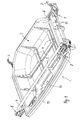
- zeigt in perspektivischer Darstellung eine Ausführungsform einer erfindungsgemäßen Stauvorrichtung, wobei sich das Aufnahmebehältnis in seiner Ruheposition befindet,
- Fig. 2
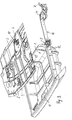
- die Stauvorrichtung nach Fig. 1, wobei die Anordnung der Stauvorrichtung unterhalb einer fahrzeugfesten Deckwandung des Kofferraumes erkennbar ist,
- Fig. 3
- die Stauvorrichtung nach Fig. 2, wobei das Aufnahmebehältnis in seine Stauposition ausgezogen ist,
- Fig. 4
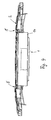
- eine heckseitige Ansicht des Stauvorrichtung nach den Fig. 1 bis 3,
- Fig. 5
- ein Einsatzteil für einen Aufnahmebereich in der Deckwandung, um das Einführen und Sichern eines Einhängehakens der Stauvorrichtung zu ermöglichen und
- Fig. 6
- das Einsatzteil nach Fig. 5 in um 180° gedrehter Darstellung.
- Eine Stauvorrichtung gemäß den Fig. 1 bis 6 ist für einen Kofferraum eines Personenkraftwagens vorgesehen. Der Kofferraum wird in grundsätzlich bekannter Weise nach unten durch einen Kofferraumboden und nach oben durch einen Kofferraumdeckel sowie in Fahrzeuglängsrichtung anschließend an den Kofferraumdeckel durch eine Deckwandung 2 begrenzt. Die Deckwandung 2 stellt ein Karosserierohbauteil dar, das fest in die Karosserierohbaustruktur eingebunden ist. Wie anhand der Fig. 2 und 3 erkennbar ist, ist die fahrzeugfeste Deckwandung 2 mit zwei in Fahrzeugquerrichtung zueinander beabstandeten, in normaler Fahrzeugausrichtung gesehen vorderen Aufnahmebereichen 10 sowie mit zwei hinteren Aufnahmebereichen 9 versehen, die Durchtritte in der Deckwandung 2 darstellen. Die vorderen Aufnahmebereiche sind etwa viereckig ausgeführt. Die hinteren Aufnahmebereiche 9 weisen eine etwa ovale Durchtrittsöffnung auf. In die vorderen Aufnahmebereiche ist gemäß den Fig. 5 und 6 jeweils ein Einsatzteil 17 einsetzbar, das mit einem Einführsteg 21 und mehreren Raststegen 20 versehen ist, die längs der Randkontur des entsprechenden Aufnahmebereiches 10 verlaufen und ein Einrasten des Einsatzteiles 17 in den entsprechenden Aufnahmebereich 10 ermöglichen. Das jeweilige Einsatzteil 17 wird von unten her, d.h. vom Kofferraum aus, in den entsprechenden Aufnahmebereich 10 eingeführt und durch einfaches Eindrücken in diesem eingerastet. Die beiden Einsatzteile 17 für die vorderen Aufnahmebereiche 10 dienen dazu, in nachfolgend näher beschriebener Weise das Einführen und Sichern von Einhängehaken eines Rahmenmodules 4, 5, 6 der Stauvorrichtung zu ermöglichen.
- Die Stauvorrichtung 1 weist eine Kunststoffwanne 3 auf, die mit Hilfe von Befestigungsmitteln 12 an ihren gegenüberliegenden Längsseiten mittels jeweils einer Führungsschienenanordnung 16 an dem Rahmenmodul 4 bis 6 linear verschiebbar befestigt ist. Das Rahmenmodul 4 bis 6 weist zwei parallel zu den Führungsschienenanordnungen 16 verlaufende Längsträgerprofile 4 auf, die durch zwei Querträger 5, 6 zu einem viereckigen Rahmen stabil miteinander verbunden sind. Ein vorderer Querträger 6 verläuft etwa auf Höhe der vorderen Einhängehaken 7, die an den Längsträgern 4 angeformt sind und zum Einhängen in die Einsatzteile 17 der vorderen Aufnahmebereiche 10 der Deckwandung 2 dienen. Ein hinterer Querträger erstreckt sich zwischen den hinteren Endbereichen der Längsträger 4 oberhalb der Kunststoffwanne 3 und ist ebenfalls fest mit diesen verbunden. Im Bereich des hinteren Querträgers 5 sind die hinteren Befestigungsmittel 8 an dem Rahmenmodul 4 bis 6 angeordnet, die als Spannelemente in Form von Bajonettverschlussteilen ausgeführt sind. Jedes Spannelement 8 ist an seiner Unterseite mit einem Handgriff und an seiner Oberseite mit einem radial abragenden Exzenterzapfen versehen. Um das Rahmenmodul einschließlich der Führungsschienenanordnungen 16 und der daran befestigten Kunststoffwanne 3 an der Unterseite der Deckwandung 2 befestigen zu können, wird zunächst die gesamte Einheit vom Kofferraum aus derart schräg nach oben gerichtet, dass die Einhängehaken 7 in entsprechende Einführschlitze 18 der Einsatzteile 17 der vorderen Aufnahmebereiche 10 eingeführt werden können. Zentrierschrägen 22 an den Einsatzteilen 17 dienen als Einführhilfe für die Einhängehaken 7. Sobald die Einhängehaken 7 nach oben durch die Einführschlitze 18 hindurchgeführt sind, gleiten die Einhängehaken zwischen zwei Zentriernocken in jedem Einsatzteil 17 über einen Absatz 19 und übergreifen diesen Absatz am vorderen Randbereich des Einführsteges 21. Das übrige Rahmenmodul 4 bis 6 wird während des Einführvorganges im Bereich der Einhängehaken 7 in seinem hinteren Bereich nach oben verschwenkt, wodurch die Exzenterzapfen oder Exzenternocken der Spannelemente 8 in ihrer Demontagenstellung durch die ovalen hinteren Aufnahmebereiche 9 der Deckwandung 2 hindurchgeführt werden können. Durch ein einfaches Verdrehen der Betätigungsgriffe werden die Exzenternocken an jeweils einer entsprechenden Anlaufschräge im Bereich der Oberseite der Deckwandung verspannt und verriegeln somit zwangsläufig das Rahmenmodul 4 bis 6 an der Unterseite der Deckwandung 2. Eine Demontage der Stauvorrichtung und damit des Rahmenmoduls 4 bis 6 erfolgt in entsprechender umgekehrter Weise, indem zunächst die Spannelemente 8 mittels einer Drehung der Betätigungsgriffe gelöst werden, so dass die Spannelemente 8 aus den hinteren Aufnahmebereichen 9 nach unten ausgeführt werden können. Anschließend werden die Einhängehaken 7 aus den vorderen Aufnahmebereichen 10 und aus den vorderen Einsatzteilen 17 wieder herausgenommen.
- Wie anhand der Fig. 1 bis 3 erkennbar ist, ist die Kunststoffwanne 3 mit ihren gegenüberliegenden seitlichen Randbereichen auf jeweils einer Führungsschienenanordnung 16 abgestützt und an entsprechend beweglichen Schienenteilen mittels der Befestigungselemente 12, die vorzugsweise als Schraubelemente ausgeführt sind, befestigt. Jede Führungsschienenanordnung 16 ist aus mehreren, teleskopförmig ausziehbaren Schienenteilen zusammengesetzt, die vorzugsweise über Wälz-oder Gleitlagerungen vorzugsweise spielfrei verschiebbar relativ zueinander gelagert sind. Die Kunststoffwanne 3 ist mit mehreren längs- und querverlaufenden Verrippungen 11 versehen, die in dem Bodenbereich der Kunststoffwanne 3 vorgesehen sind und bis in den nach oben gezogenen Wandungsbereich der Kunststoffwanne 3 geführt sind. Die Verrippungen 11 sind vorzugsweise durch entsprechende Tiefziehvorgänge einstückig in der Kunststoffwanne 3 ausgeformt.
- Ein querverlaufender, heckseitiger Wandungsbereich der Kunststoffwanne 3 ist mit einer einstückig in die Kunststoffwanne 3 integrierten Abschlussblende 14 versehen, die mit einem von oben nach unten durchgängig offenen Aussparungsbereich 13 versehen ist. Der Aussparungsbereich 13 ist nach oben und nach unten offen und weist einen horizontalen freien Querschnitt auf, der wenigstens einer Grundfläche einer in der Deckwandung 2 integrierten Kofferraumleuchte 15 entspricht. In der montierten Position des Rahmenmodules 4 bis 6 und in der geschlossenen Ruheposition der Stauvorrichtung, in der die Kunststoffwanne 3 gemäß den Fig. 1 und 2 bis zu einem vorderen Endanschlag in den Kofferraum hinein nach vorne geschoben ist, fluchtet der Aussparungsbereich 13 in vertikaler Richtung mit der Kofferraumleuchte 15. Die Kofferraumleuchte 15 kann somit ihr Licht durch den Aussparungsbereich 13 hindurch in den darunterliegenden Kofferraumbereich strahlen. Bei in Ruheposition befindlicher Kunststoffwanne ist somit die Kofferraumbeleuchtung durch die Kofferraumleuchte 15 nicht beeinträchtigt. Sobald die Kunststoffwanne in ihre gemäß Fig. 3 geöffnete Stauposition nach hinten ausgezogen ist, beleuchtet die Kofferraumleuchte 15 das Innere der Kunststoffwanne 3. Ein zusätzliche Beleuchtung für die Stauvorrichtung und damit insbesondere für das Innere der Kunststoffwanne 3 ist hierdurch nicht notwendig.
- Die Abschlussblende 14 ist einschließlich des Aussparungsbereichs 13 zudem so ausgeführt, dass im Bereich der Abschlussblende 14 und/oder in dem Aussparungsbereich 13 eine Griffmulde oder eine Griffaussparung gebildet ist, die das manuelle Ergreifen der Kunststoffwanne 3 für einen Auszieh- oder Einschubvorgang ermöglicht.
Claims (12)
- Stauvorrichtung für einen Kofferraum eines Kraftfahrzeugs mit einer zwischen einer Ruheposition und einer Stauposition durch Führungsmittel beweglich gelagerten Aufnahmebehältnis, dadurch gekennzeichnet, dass die Führungsmittel (16) und das Aufnahmebehältnis (3) an einem Rahmenmodul (4 bis 6) angeordnet sind, das durch werkzeuglos bedienbare Befestigungsmittel (7, 8) lösbar an einem Wandungsabschnitt (2) des Kofferraumes montierbar ist.
- Stauvorrichtung nach Anspruch 1, dadurch gekennzeichnet, dass als Wandungsabschnitt eine Deckwandung (2) des Kofferraumes vorgesehen ist, an der das Rahmenmodul (4 bis 6) von unten her befestigbar ist.
- Stauvorrichtung nach Anspruch 2, dadurch gekennzeichnet, dass in der Deckwandung (2) Aufnahmebereiche (9, 10) vorgesehen sind, in denen die Befestigungsmittel (7, 8) formschlüssig verankerbar sind.
- Stauvorrichtung nach Anspruch 1, dadurch gekennzeichnet, dass die Befestigungsmittel mehrere zueinander beabstandete Befestigungselemente aufweisen, die wenigstens einen Einhängehaken (7) und wenigstens ein Spannelement (8), insbesondere ein Bajonettverschlussteil, umfassen.
- Stauvorrichtung nach Anspruch 4, dadurch gekennzeichnet, dass zwei Einhängehaken (7) als vorderes Befestigungselementpaar und zwei insbesondere drehbewegliche Spannelemente (8) als hinteres Spannelementpaar vorgesehen sind, die derart gestaltet sind, dass eine spielfreie Fixierung in montierter Position erreicht wird.
- Stauvorrichtung nach Anspruch 1, dadurch gekennzeichnet, dass die Führungsmittel als teleskopartig ausziehbare Führungsschienenanordnungen (16) gestaltet sind.
- Stauvorrichtung nach Anspruch 1, dadurch gekennzeichnet, dass das Rahmenmodul ein Rahmengerüst aus zwei Längsträgern (4), an denen die Führungsschienenanordnungen (16) vorgesehen sind, und aus zwei im Bereich des vorderen Befestigungselementpaares und des hinteren Spannelementpaares angeordneten Querträgern (5, 6) aufweist.
- Stauvorrichtung nach Anspruch 1, dadurch gekennzeichnet, dass im Bereich der Deckwandung (2) eine Kofferraumleuchte (15) vorgesehen ist, die bei in Stauposition überführtem Aufnahmebehältnis (3) das Innere des Aufnahmebehältnisses (3) beleuchtet.
- Stauvorrichtung nach Anspruch 8, dadurch gekennzeichnet, dass das Aufnahmebehältnis (3) mit einem Aussparungsbereich (13) versehen ist, der bei in Ruheposition befindlichem Aufnahmebehältnis (3) derart fluchtend unterhalb der Kofferraumleuchte (15) positioniert ist, dass das Licht der Kofferraumleuchte (15) durch den Aussparungsbereich (13) hindurch nach unten in den Kofferraum strahlt.
- Stauvorrichtung nach einem der vorhergehenden Ansprüche, dadurch gekennzeichnet, dass das Aufnahmebehältnis als Kunststoffwanne (3) gestaltet ist, die wenigstens in ihrem Bodenbereich mit mehreren quer- und längsverlaufenden Verrippungen (11) versehen ist.
- Stauvorrichtung nach Anspruch 10, dadurch gekennzeichnet, dass der Aussparungsbereich (13) in einem in Ausziehrichtung vorderen Randbereich der Kunststoffwanne (3) angeordnet ist, und dass der Aussparungsbereich einen Griffbereich zum manuellen Ergreifen der Kunststoffwanne (3) umfasst.
- Stauvorrichtung nach einem der vorhergehenden Ansprüche, dadurch gekennzeichnet, dass die Kunststoffwanne (3) frontseitig mit einer Abschlussblende (14) versehen ist, die insbesondere einstückiger Teil der Kunststoffwanne ist.
Priority Applications (1)
| Application Number | Priority Date | Filing Date | Title |
|---|---|---|---|
| EP07017269A EP1897754B1 (de) | 2005-06-01 | 2006-05-10 | Stauvorrichtung für einen Kofferraum eines Kraftfahrzeuges |
Applications Claiming Priority (1)
| Application Number | Priority Date | Filing Date | Title |
|---|---|---|---|
| DE102005026670A DE102005026670B4 (de) | 2005-06-01 | 2005-06-01 | Stauvorrichtung für einen Kofferraum eines Kraftfahrzeugs |
Related Child Applications (2)
| Application Number | Title | Priority Date | Filing Date |
|---|---|---|---|
| EP07017269A Division EP1897754B1 (de) | 2005-06-01 | 2006-05-10 | Stauvorrichtung für einen Kofferraum eines Kraftfahrzeuges |
| EP07017269.7 Division-Into | 2007-09-04 |
Publications (2)
| Publication Number | Publication Date |
|---|---|
| EP1728683A1 true EP1728683A1 (de) | 2006-12-06 |
| EP1728683B1 EP1728683B1 (de) | 2011-04-13 |
Family
ID=36685802
Family Applications (2)
| Application Number | Title | Priority Date | Filing Date |
|---|---|---|---|
| EP07017269A Not-in-force EP1897754B1 (de) | 2005-06-01 | 2006-05-10 | Stauvorrichtung für einen Kofferraum eines Kraftfahrzeuges |
| EP06009614A Not-in-force EP1728683B1 (de) | 2005-06-01 | 2006-05-10 | Kofferraum eines Kraftfahrzeuges |
Family Applications Before (1)
| Application Number | Title | Priority Date | Filing Date |
|---|---|---|---|
| EP07017269A Not-in-force EP1897754B1 (de) | 2005-06-01 | 2006-05-10 | Stauvorrichtung für einen Kofferraum eines Kraftfahrzeuges |
Country Status (6)
| Country | Link |
|---|---|
| US (1) | US7229114B2 (de) |
| EP (2) | EP1897754B1 (de) |
| JP (1) | JP2006335348A (de) |
| KR (1) | KR20060125529A (de) |
| AT (2) | ATE457898T1 (de) |
| DE (3) | DE102005026670B4 (de) |
Cited By (1)
| Publication number | Priority date | Publication date | Assignee | Title |
|---|---|---|---|---|
| WO2008046461A1 (de) * | 2006-10-21 | 2008-04-24 | Audi Ag | Staufacheinrichtung für fahrzeuge |
Families Citing this family (3)
| Publication number | Priority date | Publication date | Assignee | Title |
|---|---|---|---|---|
| US7794004B2 (en) * | 2008-09-29 | 2010-09-14 | Honda Motor Co., Ltd. | Multi-compartment cargo system |
| DE102011009210A1 (de) | 2011-01-22 | 2012-07-26 | GM Global Technology Operations LLC (n. d. Gesetzen des Staates Delaware) | Befestigungsvorrichtung, Ladebodensystem, Laderaum und Kraftfahrzeug |
| DE202021001698U1 (de) | 2021-05-07 | 2022-08-11 | travelite GmbH + Co. KG | Packplatte mit stufenloser Höhenverstellung |
Citations (6)
| Publication number | Priority date | Publication date | Assignee | Title |
|---|---|---|---|---|
| US5046913A (en) | 1990-02-08 | 1991-09-10 | Domek Robert F | Quick install and remove slidable carrying table for vehicles |
| DE4442942A1 (de) | 1994-12-02 | 1996-06-05 | Hans Georg Dipl Ing Platsch | Heißluft-Blasleiste zur Verwendung in der Drucktechnik |
| US5855310A (en) * | 1997-02-18 | 1999-01-05 | Lear Corporation | Removable interior storage container for motor vehicle |
| DE10112272A1 (de) | 2000-03-17 | 2001-10-04 | Toyoda Boshoku Kk | Kofferraum für ein Fahrzeug |
| US20040217616A1 (en) | 2000-07-05 | 2004-11-04 | Klaus Haspel | Loading compartment for a motor vehicle |
| EP1642777A1 (de) * | 2004-09-30 | 2006-04-05 | BOS GmbH & Co. KG | Kraftfahrzeug mit mehreren Unterbringungsorten für Modulboxen |
Family Cites Families (25)
| Publication number | Priority date | Publication date | Assignee | Title |
|---|---|---|---|---|
| US2091070A (en) * | 1936-04-10 | 1937-08-24 | Kelch Heater Company | Deck loader and unloader |
| US2483478A (en) * | 1946-06-10 | 1949-10-04 | Helen May Smelker | Automobile tent |
| US2490014A (en) * | 1947-01-14 | 1949-12-06 | Brand Daniel Tobias D Villiers | Trailer for motor vehicles |
| US2867471A (en) * | 1955-11-21 | 1959-01-06 | Jr Allen B Coon | Camping apparatus for station wagons |
| US2934248A (en) * | 1956-06-25 | 1960-04-26 | Jack A Lown | Station wagon platform accessory |
| US2953287A (en) * | 1958-02-11 | 1960-09-20 | Schofield Mfg Company | Retractable package carrier for automobile trunks |
| US3002665A (en) * | 1959-11-16 | 1961-10-03 | Lyndon B Allen | Article receptacle for automobiles |
| FR1390288A (fr) * | 1964-01-06 | 1965-02-26 | Simca Automobiles Sa | Table incorporée à un véhicule automobile du type break |
| US3726422A (en) * | 1971-03-18 | 1973-04-10 | A Zelin | Sliding luggage rack for station wagons |
| US4193649A (en) * | 1979-01-22 | 1980-03-18 | Zev Sharon | Anti-tilt bracket and clip assembly for adjustable drawers or similar articles |
| US4452151A (en) * | 1981-12-09 | 1984-06-05 | Jarrard George A | Trunk lid folding table |
| US4455948A (en) * | 1982-06-14 | 1984-06-26 | Israel Torres | Automotive trunk table |
| FR2557517A1 (fr) * | 1983-12-28 | 1985-07-05 | Lorioux Gerard | Dispositif de rangement et de protection contre le bris d'un toit ouvrant amovible en verre dans un vehicule de tourisme automobile |
| DE4442042A1 (de) * | 1994-11-25 | 1996-05-30 | Naeher Georg Gmbh | Kofferraumverstauvorrichtung |
| US5669537A (en) * | 1996-06-03 | 1997-09-23 | Ford Global Technologies, Inc. | Portable multi-position vehicle storage unit |
| DE29718678U1 (de) * | 1997-10-21 | 1998-02-12 | J.C.F. Kaufmann Metallwarenwerk GmbH & Co. KG, 42327 Wuppertal | Ausziehbarer Behälter, insbesondere als Abfallbehälter in Schienenfahrzeugen |
| US6050202A (en) * | 1998-07-22 | 2000-04-18 | Prince Corporation | Storage divider shelf |
| US6076908A (en) * | 1998-09-17 | 2000-06-20 | Platt And Labonia Co. | Drawer for storage cabinet |
| US6338518B1 (en) * | 1999-02-27 | 2002-01-15 | Lear Corporation | Rear vehicle storage system |
| JP2001047943A (ja) * | 1999-08-03 | 2001-02-20 | Toyoda Spinning & Weaving Co Ltd | 車両用荷室構造 |
| US6290278B1 (en) * | 2000-05-05 | 2001-09-18 | Daimlerchrysler Corporation | Trunk liner |
| US6866154B2 (en) * | 2002-12-03 | 2005-03-15 | Dell Products L.P. | Tool-less attachment bracket |
| US6923354B2 (en) * | 2002-12-24 | 2005-08-02 | Garth Axelson | Tailgate toolbox |
| US6811196B2 (en) * | 2003-01-13 | 2004-11-02 | Collins & Aikman Products Co. | Vehicle cargo management apparatus having movable cargo support arm |
| US7052066B2 (en) * | 2003-02-06 | 2006-05-30 | Mark Emery | Sliding, portable, vehicle mounted combination trunk-workbench with variable height adjustment |
-
2005
- 2005-06-01 DE DE102005026670A patent/DE102005026670B4/de not_active Expired - Fee Related
-
2006
- 2006-05-10 DE DE502006006184T patent/DE502006006184D1/de active Active
- 2006-05-10 AT AT07017269T patent/ATE457898T1/de active
- 2006-05-10 DE DE502006009290T patent/DE502006009290D1/de active Active
- 2006-05-10 EP EP07017269A patent/EP1897754B1/de not_active Not-in-force
- 2006-05-10 EP EP06009614A patent/EP1728683B1/de not_active Not-in-force
- 2006-05-10 AT AT06009614T patent/ATE505363T1/de active
- 2006-05-30 KR KR1020060048594A patent/KR20060125529A/ko not_active Withdrawn
- 2006-05-31 US US11/444,038 patent/US7229114B2/en not_active Expired - Fee Related
- 2006-06-01 JP JP2006153804A patent/JP2006335348A/ja active Pending
Patent Citations (6)
| Publication number | Priority date | Publication date | Assignee | Title |
|---|---|---|---|---|
| US5046913A (en) | 1990-02-08 | 1991-09-10 | Domek Robert F | Quick install and remove slidable carrying table for vehicles |
| DE4442942A1 (de) | 1994-12-02 | 1996-06-05 | Hans Georg Dipl Ing Platsch | Heißluft-Blasleiste zur Verwendung in der Drucktechnik |
| US5855310A (en) * | 1997-02-18 | 1999-01-05 | Lear Corporation | Removable interior storage container for motor vehicle |
| DE10112272A1 (de) | 2000-03-17 | 2001-10-04 | Toyoda Boshoku Kk | Kofferraum für ein Fahrzeug |
| US20040217616A1 (en) | 2000-07-05 | 2004-11-04 | Klaus Haspel | Loading compartment for a motor vehicle |
| EP1642777A1 (de) * | 2004-09-30 | 2006-04-05 | BOS GmbH & Co. KG | Kraftfahrzeug mit mehreren Unterbringungsorten für Modulboxen |
Cited By (1)
| Publication number | Priority date | Publication date | Assignee | Title |
|---|---|---|---|---|
| WO2008046461A1 (de) * | 2006-10-21 | 2008-04-24 | Audi Ag | Staufacheinrichtung für fahrzeuge |
Also Published As
| Publication number | Publication date |
|---|---|
| EP1897754B1 (de) | 2010-02-17 |
| DE102005026670A1 (de) | 2006-12-07 |
| EP1897754A3 (de) | 2008-03-19 |
| DE502006006184D1 (de) | 2010-04-01 |
| EP1897754A2 (de) | 2008-03-12 |
| ATE457898T1 (de) | 2010-03-15 |
| ATE505363T1 (de) | 2011-04-15 |
| US20060273611A1 (en) | 2006-12-07 |
| KR20060125529A (ko) | 2006-12-06 |
| US7229114B2 (en) | 2007-06-12 |
| JP2006335348A (ja) | 2006-12-14 |
| DE502006009290D1 (de) | 2011-05-26 |
| EP1728683B1 (de) | 2011-04-13 |
| DE102005026670B4 (de) | 2009-04-02 |
Similar Documents
| Publication | Publication Date | Title |
|---|---|---|
| DE60018357T2 (de) | Dachlastträger | |
| DE102009016275B3 (de) | Heckklappenscharnier für Kraftfahrzeug mit zwei Schwenkachsen | |
| DE19721877A1 (de) | Ablagevorrichtung für Fahrzeuge | |
| DE10125726A1 (de) | Aufnahmevorrichtung für einem Laderaum eines Kraftfahrzeugs | |
| DE102004022835B4 (de) | Kraftfahrzeug mit einer Vorrichtung zur Aufnahme von Gegenständen | |
| DE19858429B4 (de) | Vorrichtung zur Sicherung von Funktionseinheiten in einem Laderaum eines Kraftfahrzeuges und Deckabschnitt hierfür | |
| EP0504588B1 (de) | Abdeckkappenanordnung am Querträger eines Dachgepäckträgers | |
| DE102005026670B4 (de) | Stauvorrichtung für einen Kofferraum eines Kraftfahrzeugs | |
| EP1873014B1 (de) | Konsole für ein Fahrzeug | |
| DE102012205912B4 (de) | Heckraum-Bodenstruktur eines Kraftfahrzeugs | |
| DE102007002822A1 (de) | Variabler Raumteiler für einen Fahrzeugladeraum | |
| DE102017210120B4 (de) | Laderaumabdeckung und Kraftfahrzeug | |
| DE102008019396B4 (de) | Laderaum für ein Kraftfahrzeug | |
| DE102006032807A1 (de) | Abdeckung für einen Gepäckraum | |
| DE10061954A1 (de) | Hecktransportsystem | |
| DE102021121908B3 (de) | Einrichtungssystem zur Montage von einem Fahrzeugmodul in einem Fahrzeug sowie Montageverfahren | |
| DE102008055907B4 (de) | Befestigungssystem für Funktionselemente in einem Kraftfahrzeug | |
| DE102014204679B4 (de) | Ladebodeneinrichtung für einen Laderaum eines Personenkraftwagens | |
| DE102005012008B4 (de) | Kraftfahrzeug | |
| DE102012013013A1 (de) | Ablagevorrichtung für den Gepäckraum eines Fahrzeugs | |
| EP2765032B1 (de) | Lastenträger mit an einem Grundträger beweglich gelagerten Lasttragteilen | |
| DE19731370C1 (de) | Schutzwand für ein Kraftfahrzeug | |
| DE10321343B4 (de) | Fahrzeug mit einer Abdeckplatte für einen Stauraum, insbesondere für eine Reserveradmulde | |
| DE102005026671A1 (de) | Stauvorrichtung für einen Fahrzeugkofferraum | |
| EP1072473B1 (de) | Kraftfahrzeug mit einem Behälteraufbau für Frachtgut |
Legal Events
| Date | Code | Title | Description |
|---|---|---|---|
| PUAI | Public reference made under article 153(3) epc to a published international application that has entered the european phase |
Free format text: ORIGINAL CODE: 0009012 |
|
| AK | Designated contracting states |
Kind code of ref document: A1 Designated state(s): AT BE BG CH CY CZ DE DK EE ES FI FR GB GR HU IE IS IT LI LT LU LV MC NL PL PT RO SE SI SK TR |
|
| AX | Request for extension of the european patent |
Extension state: AL BA HR MK YU |
|
| 17P | Request for examination filed |
Effective date: 20070123 |
|
| 17Q | First examination report despatched |
Effective date: 20070301 |
|
| AKX | Designation fees paid |
Designated state(s): AT BE BG CH CY CZ DE DK EE ES FI FR GB GR HU IE IS IT LI LT LU LV MC NL PL PT RO SE SI SK TR |
|
| RTI1 | Title (correction) |
Free format text: VEHICLE BOOT |
|
| GRAP | Despatch of communication of intention to grant a patent |
Free format text: ORIGINAL CODE: EPIDOSNIGR1 |
|
| GRAS | Grant fee paid |
Free format text: ORIGINAL CODE: EPIDOSNIGR3 |
|
| GRAA | (expected) grant |
Free format text: ORIGINAL CODE: 0009210 |
|
| AK | Designated contracting states |
Kind code of ref document: B1 Designated state(s): AT BE BG CH CY CZ DE DK EE ES FI FR GB GR HU IE IS IT LI LT LU LV MC NL PL PT RO SE SI SK TR |
|
| REG | Reference to a national code |
Ref country code: GB Ref legal event code: FG4D Free format text: NOT ENGLISH |
|
| REG | Reference to a national code |
Ref country code: CH Ref legal event code: EP |
|
| REG | Reference to a national code |
Ref country code: IE Ref legal event code: FG4D Free format text: LANGUAGE OF EP DOCUMENT: GERMAN |
|
| REF | Corresponds to: |
Ref document number: 502006009290 Country of ref document: DE Date of ref document: 20110526 Kind code of ref document: P |
|
| REG | Reference to a national code |
Ref country code: DE Ref legal event code: R096 Ref document number: 502006009290 Country of ref document: DE Effective date: 20110526 |
|
| REG | Reference to a national code |
Ref country code: NL Ref legal event code: VDEP Effective date: 20110413 |
|
| LTIE | Lt: invalidation of european patent or patent extension |
Effective date: 20110413 |
|
| PG25 | Lapsed in a contracting state [announced via postgrant information from national office to epo] |
Ref country code: PT Free format text: LAPSE BECAUSE OF FAILURE TO SUBMIT A TRANSLATION OF THE DESCRIPTION OR TO PAY THE FEE WITHIN THE PRESCRIBED TIME-LIMIT Effective date: 20110816 Ref country code: LT Free format text: LAPSE BECAUSE OF FAILURE TO SUBMIT A TRANSLATION OF THE DESCRIPTION OR TO PAY THE FEE WITHIN THE PRESCRIBED TIME-LIMIT Effective date: 20110413 Ref country code: SE Free format text: LAPSE BECAUSE OF FAILURE TO SUBMIT A TRANSLATION OF THE DESCRIPTION OR TO PAY THE FEE WITHIN THE PRESCRIBED TIME-LIMIT Effective date: 20110413 |
|
| REG | Reference to a national code |
Ref country code: IE Ref legal event code: FD4D |
|
| BERE | Be: lapsed |
Owner name: BAYERISCHE MOTOREN WERKE A.G. Effective date: 20110531 Owner name: BOS G.M.B.H. & CO. KG Effective date: 20110531 |
|
| PG25 | Lapsed in a contracting state [announced via postgrant information from national office to epo] |
Ref country code: CY Free format text: LAPSE BECAUSE OF FAILURE TO SUBMIT A TRANSLATION OF THE DESCRIPTION OR TO PAY THE FEE WITHIN THE PRESCRIBED TIME-LIMIT Effective date: 20110413 Ref country code: FI Free format text: LAPSE BECAUSE OF FAILURE TO SUBMIT A TRANSLATION OF THE DESCRIPTION OR TO PAY THE FEE WITHIN THE PRESCRIBED TIME-LIMIT Effective date: 20110413 Ref country code: LV Free format text: LAPSE BECAUSE OF FAILURE TO SUBMIT A TRANSLATION OF THE DESCRIPTION OR TO PAY THE FEE WITHIN THE PRESCRIBED TIME-LIMIT Effective date: 20110413 Ref country code: SI Free format text: LAPSE BECAUSE OF FAILURE TO SUBMIT A TRANSLATION OF THE DESCRIPTION OR TO PAY THE FEE WITHIN THE PRESCRIBED TIME-LIMIT Effective date: 20110413 Ref country code: ES Free format text: LAPSE BECAUSE OF FAILURE TO SUBMIT A TRANSLATION OF THE DESCRIPTION OR TO PAY THE FEE WITHIN THE PRESCRIBED TIME-LIMIT Effective date: 20110724 Ref country code: IS Free format text: LAPSE BECAUSE OF FAILURE TO SUBMIT A TRANSLATION OF THE DESCRIPTION OR TO PAY THE FEE WITHIN THE PRESCRIBED TIME-LIMIT Effective date: 20110813 Ref country code: GR Free format text: LAPSE BECAUSE OF FAILURE TO SUBMIT A TRANSLATION OF THE DESCRIPTION OR TO PAY THE FEE WITHIN THE PRESCRIBED TIME-LIMIT Effective date: 20110714 |
|
| PG25 | Lapsed in a contracting state [announced via postgrant information from national office to epo] |
Ref country code: MC Free format text: LAPSE BECAUSE OF NON-PAYMENT OF DUE FEES Effective date: 20110531 Ref country code: NL Free format text: LAPSE BECAUSE OF FAILURE TO SUBMIT A TRANSLATION OF THE DESCRIPTION OR TO PAY THE FEE WITHIN THE PRESCRIBED TIME-LIMIT Effective date: 20110413 |
|
| REG | Reference to a national code |
Ref country code: CH Ref legal event code: PL |
|
| PG25 | Lapsed in a contracting state [announced via postgrant information from national office to epo] |
Ref country code: CZ Free format text: LAPSE BECAUSE OF FAILURE TO SUBMIT A TRANSLATION OF THE DESCRIPTION OR TO PAY THE FEE WITHIN THE PRESCRIBED TIME-LIMIT Effective date: 20110413 Ref country code: CH Free format text: LAPSE BECAUSE OF NON-PAYMENT OF DUE FEES Effective date: 20110531 Ref country code: EE Free format text: LAPSE BECAUSE OF FAILURE TO SUBMIT A TRANSLATION OF THE DESCRIPTION OR TO PAY THE FEE WITHIN THE PRESCRIBED TIME-LIMIT Effective date: 20110413 Ref country code: IE Free format text: LAPSE BECAUSE OF FAILURE TO SUBMIT A TRANSLATION OF THE DESCRIPTION OR TO PAY THE FEE WITHIN THE PRESCRIBED TIME-LIMIT Effective date: 20110413 Ref country code: LI Free format text: LAPSE BECAUSE OF NON-PAYMENT OF DUE FEES Effective date: 20110531 |
|
| PLBE | No opposition filed within time limit |
Free format text: ORIGINAL CODE: 0009261 |
|
| STAA | Information on the status of an ep patent application or granted ep patent |
Free format text: STATUS: NO OPPOSITION FILED WITHIN TIME LIMIT |
|
| PG25 | Lapsed in a contracting state [announced via postgrant information from national office to epo] |
Ref country code: DK Free format text: LAPSE BECAUSE OF FAILURE TO SUBMIT A TRANSLATION OF THE DESCRIPTION OR TO PAY THE FEE WITHIN THE PRESCRIBED TIME-LIMIT Effective date: 20110413 Ref country code: PL Free format text: LAPSE BECAUSE OF FAILURE TO SUBMIT A TRANSLATION OF THE DESCRIPTION OR TO PAY THE FEE WITHIN THE PRESCRIBED TIME-LIMIT Effective date: 20110413 Ref country code: RO Free format text: LAPSE BECAUSE OF FAILURE TO SUBMIT A TRANSLATION OF THE DESCRIPTION OR TO PAY THE FEE WITHIN THE PRESCRIBED TIME-LIMIT Effective date: 20110413 Ref country code: SK Free format text: LAPSE BECAUSE OF FAILURE TO SUBMIT A TRANSLATION OF THE DESCRIPTION OR TO PAY THE FEE WITHIN THE PRESCRIBED TIME-LIMIT Effective date: 20110413 |
|
| 26N | No opposition filed |
Effective date: 20120116 |
|
| PG25 | Lapsed in a contracting state [announced via postgrant information from national office to epo] |
Ref country code: BE Free format text: LAPSE BECAUSE OF NON-PAYMENT OF DUE FEES Effective date: 20110531 |
|
| REG | Reference to a national code |
Ref country code: DE Ref legal event code: R097 Ref document number: 502006009290 Country of ref document: DE Effective date: 20120116 |
|
| PG25 | Lapsed in a contracting state [announced via postgrant information from national office to epo] |
Ref country code: IT Free format text: LAPSE BECAUSE OF FAILURE TO SUBMIT A TRANSLATION OF THE DESCRIPTION OR TO PAY THE FEE WITHIN THE PRESCRIBED TIME-LIMIT Effective date: 20110413 |
|
| REG | Reference to a national code |
Ref country code: AT Ref legal event code: MM01 Ref document number: 505363 Country of ref document: AT Kind code of ref document: T Effective date: 20110510 |
|
| PG25 | Lapsed in a contracting state [announced via postgrant information from national office to epo] |
Ref country code: AT Free format text: LAPSE BECAUSE OF NON-PAYMENT OF DUE FEES Effective date: 20110510 |
|
| PG25 | Lapsed in a contracting state [announced via postgrant information from national office to epo] |
Ref country code: LU Free format text: LAPSE BECAUSE OF NON-PAYMENT OF DUE FEES Effective date: 20110510 |
|
| PG25 | Lapsed in a contracting state [announced via postgrant information from national office to epo] |
Ref country code: BG Free format text: LAPSE BECAUSE OF FAILURE TO SUBMIT A TRANSLATION OF THE DESCRIPTION OR TO PAY THE FEE WITHIN THE PRESCRIBED TIME-LIMIT Effective date: 20110713 |
|
| PG25 | Lapsed in a contracting state [announced via postgrant information from national office to epo] |
Ref country code: TR Free format text: LAPSE BECAUSE OF FAILURE TO SUBMIT A TRANSLATION OF THE DESCRIPTION OR TO PAY THE FEE WITHIN THE PRESCRIBED TIME-LIMIT Effective date: 20110413 |
|
| PG25 | Lapsed in a contracting state [announced via postgrant information from national office to epo] |
Ref country code: HU Free format text: LAPSE BECAUSE OF FAILURE TO SUBMIT A TRANSLATION OF THE DESCRIPTION OR TO PAY THE FEE WITHIN THE PRESCRIBED TIME-LIMIT Effective date: 20110413 |
|
| REG | Reference to a national code |
Ref country code: FR Ref legal event code: PLFP Year of fee payment: 11 |
|
| REG | Reference to a national code |
Ref country code: FR Ref legal event code: PLFP Year of fee payment: 12 |
|
| REG | Reference to a national code |
Ref country code: FR Ref legal event code: PLFP Year of fee payment: 13 |
|
| PGFP | Annual fee paid to national office [announced via postgrant information from national office to epo] |
Ref country code: FR Payment date: 20190521 Year of fee payment: 14 |
|
| PGFP | Annual fee paid to national office [announced via postgrant information from national office to epo] |
Ref country code: GB Payment date: 20190523 Year of fee payment: 14 |
|
| REG | Reference to a national code |
Ref country code: DE Ref legal event code: R082 Ref document number: 502006009290 Country of ref document: DE Representative=s name: PATENTANWAELTE RUFF, WILHELM, BEIER, DAUSTER &, DE Ref country code: DE Ref legal event code: R081 Ref document number: 502006009290 Country of ref document: DE Owner name: BOS GMBH & CO. KG, DE Free format text: FORMER OWNERS: BAYERISCHE MOTOREN WERKE AKTIENGESELLSCHAFT, 80809 MUENCHEN, DE; BOS GMBH & CO. KG, 73760 OSTFILDERN, DE |
|
| GBPC | Gb: european patent ceased through non-payment of renewal fee |
Effective date: 20200510 |
|
| PG25 | Lapsed in a contracting state [announced via postgrant information from national office to epo] |
Ref country code: GB Free format text: LAPSE BECAUSE OF NON-PAYMENT OF DUE FEES Effective date: 20200510 Ref country code: FR Free format text: LAPSE BECAUSE OF NON-PAYMENT OF DUE FEES Effective date: 20200531 |
|
| PGFP | Annual fee paid to national office [announced via postgrant information from national office to epo] |
Ref country code: DE Payment date: 20210520 Year of fee payment: 16 |
|
| REG | Reference to a national code |
Ref country code: DE Ref legal event code: R119 Ref document number: 502006009290 Country of ref document: DE |
|
| PG25 | Lapsed in a contracting state [announced via postgrant information from national office to epo] |
Ref country code: DE Free format text: LAPSE BECAUSE OF NON-PAYMENT OF DUE FEES Effective date: 20221201 |