EP1728982A2 - Dispositif et méthode pour monter un composant dans un carter d'huile - Google Patents
Dispositif et méthode pour monter un composant dans un carter d'huile Download PDFInfo
- Publication number
- EP1728982A2 EP1728982A2 EP06002968A EP06002968A EP1728982A2 EP 1728982 A2 EP1728982 A2 EP 1728982A2 EP 06002968 A EP06002968 A EP 06002968A EP 06002968 A EP06002968 A EP 06002968A EP 1728982 A2 EP1728982 A2 EP 1728982A2
- Authority
- EP
- European Patent Office
- Prior art keywords
- fastening device
- component
- base
- oil pan
- oil
- Prior art date
- Legal status (The legal status is an assumption and is not a legal conclusion. Google has not performed a legal analysis and makes no representation as to the accuracy of the status listed.)
- Granted
Links
- 238000000034 method Methods 0.000 title claims abstract description 8
- 239000000853 adhesive Substances 0.000 claims abstract description 18
- 230000001070 adhesive effect Effects 0.000 claims abstract description 18
- 239000002184 metal Substances 0.000 claims description 10
- 239000011324 bead Substances 0.000 claims description 7
- 238000005452 bending Methods 0.000 claims description 7
- 238000004026 adhesive bonding Methods 0.000 claims description 5
- 230000005540 biological transmission Effects 0.000 claims description 2
- 230000002441 reversible effect Effects 0.000 abstract 1
- 101150006573 PAN1 gene Proteins 0.000 description 11
- 241000237983 Trochidae Species 0.000 description 5
- 238000004519 manufacturing process Methods 0.000 description 4
- 238000002788 crimping Methods 0.000 description 2
- 238000007789 sealing Methods 0.000 description 2
- 230000006978 adaptation Effects 0.000 description 1
- 230000015572 biosynthetic process Effects 0.000 description 1
- 238000002485 combustion reaction Methods 0.000 description 1
- 230000008021 deposition Effects 0.000 description 1
- 230000000694 effects Effects 0.000 description 1
- 238000004049 embossing Methods 0.000 description 1
- 238000001914 filtration Methods 0.000 description 1
- 238000009957 hemming Methods 0.000 description 1
- 238000003780 insertion Methods 0.000 description 1
- 230000037431 insertion Effects 0.000 description 1
- 238000009434 installation Methods 0.000 description 1
- 238000003754 machining Methods 0.000 description 1
- 230000035515 penetration Effects 0.000 description 1
- 238000003466 welding Methods 0.000 description 1
Images


Classifications
-
- F—MECHANICAL ENGINEERING; LIGHTING; HEATING; WEAPONS; BLASTING
- F01—MACHINES OR ENGINES IN GENERAL; ENGINE PLANTS IN GENERAL; STEAM ENGINES
- F01M—LUBRICATING OF MACHINES OR ENGINES IN GENERAL; LUBRICATING INTERNAL COMBUSTION ENGINES; CRANKCASE VENTILATING
- F01M11/00—Component parts, details or accessories, not provided for in, or of interest apart from, groups F01M1/00 - F01M9/00
-
- F—MECHANICAL ENGINEERING; LIGHTING; HEATING; WEAPONS; BLASTING
- F01—MACHINES OR ENGINES IN GENERAL; ENGINE PLANTS IN GENERAL; STEAM ENGINES
- F01M—LUBRICATING OF MACHINES OR ENGINES IN GENERAL; LUBRICATING INTERNAL COMBUSTION ENGINES; CRANKCASE VENTILATING
- F01M11/00—Component parts, details or accessories, not provided for in, or of interest apart from, groups F01M1/00 - F01M9/00
- F01M11/0004—Oilsumps
-
- F—MECHANICAL ENGINEERING; LIGHTING; HEATING; WEAPONS; BLASTING
- F01—MACHINES OR ENGINES IN GENERAL; ENGINE PLANTS IN GENERAL; STEAM ENGINES
- F01M—LUBRICATING OF MACHINES OR ENGINES IN GENERAL; LUBRICATING INTERNAL COMBUSTION ENGINES; CRANKCASE VENTILATING
- F01M11/00—Component parts, details or accessories, not provided for in, or of interest apart from, groups F01M1/00 - F01M9/00
- F01M11/0004—Oilsumps
- F01M2011/0054—Fastening to the cylinder block
-
- F—MECHANICAL ENGINEERING; LIGHTING; HEATING; WEAPONS; BLASTING
- F01—MACHINES OR ENGINES IN GENERAL; ENGINE PLANTS IN GENERAL; STEAM ENGINES
- F01M—LUBRICATING OF MACHINES OR ENGINES IN GENERAL; LUBRICATING INTERNAL COMBUSTION ENGINES; CRANKCASE VENTILATING
- F01M11/00—Component parts, details or accessories, not provided for in, or of interest apart from, groups F01M1/00 - F01M9/00
- F01M11/0004—Oilsumps
- F01M2011/007—Oil pickup tube to oil pump, e.g. strainer
-
- F—MECHANICAL ENGINEERING; LIGHTING; HEATING; WEAPONS; BLASTING
- F01—MACHINES OR ENGINES IN GENERAL; ENGINE PLANTS IN GENERAL; STEAM ENGINES
- F01M—LUBRICATING OF MACHINES OR ENGINES IN GENERAL; LUBRICATING INTERNAL COMBUSTION ENGINES; CRANKCASE VENTILATING
- F01M11/00—Component parts, details or accessories, not provided for in, or of interest apart from, groups F01M1/00 - F01M9/00
- F01M11/0004—Oilsumps
- F01M2011/0079—Oilsumps with the oil pump integrated or fixed to sump
Definitions
- the invention relates to a fastening device and a method for fastening a component in an oil pan, in particular a metallic oil pan.
- Fastening devices for mounting a component in an oil pan are known.
- WO 02/46584 A1 a metal oil pan with integrated oil filter, where the oil filter is mounted in the sump via a fastener.
- the shell of the oil filter is fastened by rivets directly to the oil pan.
- rivets are introduced, at the ends of fastening tabs are attached, which clamp the housing of the filter in the oil pan.
- the invention has for its object to provide a fastening device for components in oil pans, which makes it possible to compensate for mounting tolerances easy to attach the attachment device in the oil pan easy and can bring the component easily and accurately.
- the fastening device consists of a base part and at least one holding part arranged on the base part for producing a preferably reversibly releasable, substantially positive connection with a component, wherein the base part is connected to the oil pan, the holding part Part of the base is and the holding part is bent over a foldable area.
- the base part is a sheet metal strip. These are inexpensive to produce and can be well provided with fold areas.
- the base part, in particular the sheet-metal strip may consist of individual sections, which may be arranged on several areas of the oil pan for mounting one or more components, or be designed as a closed ring in order to achieve an optimal adaptation to the respective component.
- the component has a locking portion.
- This locking portion around a connection between the connecting element and component can be made by bending the holding part in a particularly simple manner.
- the locking portion is advantageously the outer contour of the component, since at this area a gripping with the holding part is particularly well possible.
- the shape of the base is also advantageously adapted to the shape of the locking portion of the component to create an optimal connection.
- the holding part comprises the locking portion of the component partially positively.
- the holding part comprises the locking portion of the component completely positive fit. In this case, a particularly dense connection between the component and the oil pan is possible.
- a seal is provided between the base and locking portion.
- the seal can be introduced into the fastening part.
- a seal may be provided between base and sump.
- the seal can be introduced in a simple manner, since it only has to be introduced between the base body and the locking section or oil sump.
- the seal is an adhesive.
- connection between the oil pan and the base part is made by adhesive.
- Adhesive can be applied easily and variable in particular adapted to the component shape. By gluing itself, the component can be positioned more accurately, because on the one hand, the adhesive area is specified directly, for example by imprints on the tub surface.
- the alignment of the fastening device is also very easily possible because the component is still movable for a limited period of time until the maximum holding force is achieved by curing the adhesive.
- the application of the adhesive and the subsequent attachment of the fastening device represents a significant manufacturing step reduction. The installation of the fastening device can thereby be carried out independently of the process step before or after the machining of the trough.
- the adhesive in addition to the holding forces and a seal still possible existing leaks is achieved.
- For the adhesive is advantageously applied both for the seal and for attachment as a bead.
- the invention provides that with a fastener two or more components can be attached simultaneously.
- holding parts are arranged on opposite sides of the base body.
- the oil pan is advantageously an oil pan for internal combustion engines or for an automatic transmission for motor vehicles.
- the component may be an oil filter unit, a magnet, a sensor, a pump or the like.
- an oil pan 1 made of metal is shown in exploded view. Attached to it is a fastening device 2, which has a base part 3 and holding parts 5 which are connected to one another via a folding area 4.
- the holding parts 5 are arranged in sections on the base part 3; However, it is also possible to provide a completely circumferential holding part 5.
- the fastening device 2 is made of sheet metal and has in cross-section substantially two legs and a leg connecting portion, wherein the one leg as the base part 3 and the other leg is formed as the holding part 5.
- the connecting portion forms in the installed state, when the holding part 5 is folded, a folding area 4.
- the holding parts 5 are due to the Blechverformbarkeit in the manner of a sheet metal tongue or flanging relative to the base 3 foldable, while the base 3 fixed to the bottom of sheet metal manufactured sump 1 is attached.
- the oil filter unit 6 is mounted in the oil pan 1.
- the oil filter unit 6 has a housing 7 made of plastic, which consists of a filter bottom shell 7a and a filter top shell 7b. Between filter lower shell 7a and filter upper shell 7b, a filter medium 8 is introduced. An oil outlet 9 is located on the filter top shell 7b. An oil inlet 10 is arranged on the filter bottom shell.
- the oil is sucked in from the oil sump via the oil inlet 10 in the lower filter shell 7a, passes through the filter medium 8 into the upper filter shell 7b and is supplied from there via the oil outlet 9 to the circulation again.
- the filter lower shell 7a filtered-out residues are deposited.
- a substantially planar base surface 11 is formed, on which the fastening device 2 is mounted.
- the base surface is formed as an embossing in the oil pan 1 and enters into the interior of the oil pan 1 inside.
- the course of the base surface corresponds to the outer edge of the oil pan 1 and, accordingly, the fastening device 2 is mounted along the outer edge of the oil pan.
- Adjacent to the inside of the base surface 11, a bead 12 is arranged, which serves during assembly for positional positioning of the filter bottom shell 7a.
- the filter lower shell 7a of the housing 7 is designed to be open at the bottom, so that a closed unit is formed by the oil pan bottom region 1a within the base surface 11 with the housing parts 7a and 7b.
- a protruding edge which represents the outer contour and completely revolves around the lower filter shell 7a is provided as the locking section 13.
- the edge or locking portion 13 may be formed directly on the filter bottom shell 7a, or indirectly by being formed on a separate support frame to which the filter bottom shell 7a is attached.
- a predetermined bending point 4a which is located on the holding part along the predetermined position of the upper edge of the locking portion 13, and along which the holding part 5 on the locking portion 13th is bent.
- the fastening device 2 forms a the oil filter unit 6 circulating Bördelrahmen which holds the oil filter unit 6 on its projecting edge at the bottom of the oil pan 1.
- adhesive 14 is introduced for fastening the fastening device 2 on the oil pan.
- the adhesive 14 may be punctual or continuous circumferential bead are applied.
- the gluing process allows accurate positioning of the crimping frame which the fastening device 2 forms, so that the oil filter unit can be positioned correspondingly accurately in the oil sump.
- the base part 3 and the base surface 11, as in the illustrated exemplary embodiment run completely circumferentially as a closed ring and are adapted to the outer contour of the oil filter unit 6, a continuous sealing of the filter lower shell 7a with the base surface 11 also seals the cavity between the filter lower shell 7a and the underlying oil pan bottom region 1a. This has the advantage that there can be no unwanted deposition, such as oil sump.
- the better sealing effect is achieved when the adhesive is applied as a bead. This seal can also be achieved or even enhanced if between the base part 3 of the fastening device 2 and the locking portion 13 adhesive (not shown) is introduced. By bonding between the locking portion 13 and base 3 additional holding forces between oil filter unit 6 and oil pan 1 can be achieved.
- FIG. 4 and 5 show a portion of two embodiments for bridging curve sections of the outer contour of a component.
- the holding part 5 has been made in one piece along the curve, whereas in Fig. 5, the holding parts 5 experience a break in the curved area.
- Fig. 5 also shows the predetermined bending point 4a, along which the bending takes place on a locking portion 13 of a component.
- the holding parts 5 are arranged on both sides of the base part 3 of the fastening device 2 in order to enable attachment of at least two components (not shown) to a fastening device 2.
- the holding parts 5 are bent in the direction of the arrows in Fig. 5 in order to achieve a connection of the component with the oil pan.
- components can also be magnets for filtering out metal chips from the oil, sensors or pumps with which the medium is conveyed.
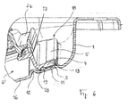
- FIG. 6 an alternative embodiment for gluing the fastening device 2 'into the oil sump 1 is illustrated.
- Fig. 6 also shows an alternative embodiment of the oil filter unit 6 '.
- the same parts as in the embodiments described above are provided with the same reference numerals.
- the oil filter unit 6 ' is composed of the filter top shell 7b, a bottom region 16 of the oil pan 1 and a carrier frame 17 which tightly connects the filter top shell 7b and the bottom region 16 of the oil pan 1 educated.
- the carrier frame 17 is connected to the metallic oil sump 1 along the entire circumference of the upper filter shell 7b via a crimping frame 18, which has the base part 3, fold 4 and holding part 5 as described above.
- a filter medium is arranged (not shown).
- Carrier frame 17 and filter top shell 7b are each made of plastic and tightly connected to each other in a known manner.
- the hemming frame 18 is welded to the oil pan 1 via its base part 3. Behind the free end of the base part 3 and parallel thereto, a groove 19 in the base part is present, which is open to the base area 11.
- the groove 19 is bounded on the side facing away from the base 3 by an edge 20 which rests on the base area 11 adjacent to the bead 12.
- Oil-tight adhesive is introduced into the area formed by the groove 19, the edge 16 and the base area 11, so that the base part 3 closes tightly to the base area 11 over the entire length of the beading frame 18.
- the bead 12 in turn serves on the one hand for prefixing and pre-positioning of the support frame 17 and on the other hand it prevents undesired penetration of adhesive into the interior of the oil filter unit 6 '.
Landscapes
- Engineering & Computer Science (AREA)
- Mechanical Engineering (AREA)
- General Engineering & Computer Science (AREA)
- Lubrication Details And Ventilation Of Internal Combustion Engines (AREA)
- Food-Manufacturing Devices (AREA)
- General Details Of Gearings (AREA)
- Connection Of Plates (AREA)
Applications Claiming Priority (1)
| Application Number | Priority Date | Filing Date | Title |
|---|---|---|---|
| DE102005025726A DE102005025726A1 (de) | 2005-06-04 | 2005-06-04 | Befestigungsvorrichtung und Verfahren zur Befestigung eines Bauteils in einer Ölwanne |
Publications (4)
| Publication Number | Publication Date |
|---|---|
| EP1728982A2 true EP1728982A2 (fr) | 2006-12-06 |
| EP1728982A3 EP1728982A3 (fr) | 2010-08-04 |
| EP1728982B1 EP1728982B1 (fr) | 2012-01-18 |
| EP1728982B9 EP1728982B9 (fr) | 2012-04-25 |
Family
ID=37027663
Family Applications (1)
| Application Number | Title | Priority Date | Filing Date |
|---|---|---|---|
| EP06002968A Expired - Lifetime EP1728982B9 (fr) | 2005-06-04 | 2006-02-14 | Dispositif et méthode pour monter un composant dans un carter d'huile |
Country Status (7)
| Country | Link |
|---|---|
| US (1) | US7383809B2 (fr) |
| EP (1) | EP1728982B9 (fr) |
| JP (1) | JP2006336657A (fr) |
| KR (1) | KR100783220B1 (fr) |
| CN (1) | CN1877091B (fr) |
| AT (1) | ATE542028T1 (fr) |
| DE (1) | DE102005025726A1 (fr) |
Cited By (1)
| Publication number | Priority date | Publication date | Assignee | Title |
|---|---|---|---|---|
| DE102008053279A1 (de) | 2008-10-27 | 2010-05-06 | Zf Friedrichshafen Ag | Ölbehälter mit integriertem Ölfilter |
Families Citing this family (20)
| Publication number | Priority date | Publication date | Assignee | Title |
|---|---|---|---|---|
| CA2597613C (fr) * | 2006-08-28 | 2011-05-03 | Honda Motor Co., Ltd. | Structure de filtre a huile et structure d'ecoulement d'huile de moteur |
| DE102007023641B4 (de) * | 2007-05-22 | 2015-04-02 | Ibs Filtran Kunststoff-/ Metallerzeugnisse Gmbh | Ölfiltervorrichtung |
| CN101688610B (zh) * | 2007-07-09 | 2013-05-01 | 阿拉暮株式会社 | 食品加工设备用密封填料件、使用了该密封填料件的食品加工设备用配管接头结构体以及食品加工设备用o型密封圈 |
| US20090139922A1 (en) * | 2007-12-04 | 2009-06-04 | Gm Global Technology Operations, Inc. | Transmission Filter System |
| DE102008014416B4 (de) | 2008-03-14 | 2014-12-18 | Ibs Filtran Kunststoff-/ Metallerzeugnisse Gmbh | Ölfiltervorrichtung |
| DE102008027662A1 (de) | 2008-06-10 | 2009-12-17 | Ibs Filtran Kunststoff- / Metallerzeugnisse Gmbh | Ölwanne mit Ölfilter |
| DE102008038958B4 (de) | 2008-08-13 | 2017-11-02 | Ibs Filtran Kunststoff-/ Metallerzeugnisse Gmbh | Ölwanne mit Ölfilter an Trägereinheit |
| US20100229821A1 (en) * | 2009-03-13 | 2010-09-16 | Filtrauto | Plastic Structural Oil Sump with Fitted-on Bottom for a Combustion Engine and Method of Fabricating such a Sump |
| DE102009036852B4 (de) * | 2009-08-10 | 2015-04-16 | Ibs Filtran Kunststoff-/ Metallerzeugnisse Gmbh | Ölwanne mit einer daran befestigten Ölfiltereinheit |
| DE102010041559A1 (de) * | 2010-09-28 | 2012-03-29 | Siemens Aktiengesellschaft | Vorrichtung zur Filterung von Schmierstoffen in einem Getriebe |
| FR2969695B1 (fr) * | 2010-12-23 | 2012-12-21 | Renault Sa | Carter d'huile pour moteur thermique |
| USD821445S1 (en) * | 2016-05-10 | 2018-06-26 | Ibs Filtran Kunststoff-/Metallerzeugnisse Gmbh | Oil pan with integrated suction filter |
| DE102016121863A1 (de) * | 2016-11-15 | 2018-05-17 | Boge Elastmetall Gmbh | Saugölfilter für ein Getriebe oder Verbrennungsmotor |
| CN109306884A (zh) * | 2017-07-28 | 2019-02-05 | 福特环球技术公司 | 具有结合的滤油器的油底壳组件 |
| US11028741B1 (en) | 2020-08-24 | 2021-06-08 | Apq Development, Llc | Oil pick-up assembly |
| US11078958B1 (en) | 2020-08-24 | 2021-08-03 | Apq Development, Llc | Compression limiter |
| USD916152S1 (en) | 2020-08-24 | 2021-04-13 | Apq Development, Llc | Compression limiter |
| USD921045S1 (en) | 2020-08-24 | 2021-06-01 | Apq Development, Llc | Oil pick-up assembly |
| DE102021114927A1 (de) | 2021-06-10 | 2022-12-15 | Schaeffler Technologies AG & Co. KG | Ölgehäusewanne mit Ölfilterelement |
| DE102023133537A1 (de) * | 2023-11-30 | 2025-06-05 | Bayerische Motoren Werke Aktiengesellschaft | Befestigungseinrichtung und Verfahren zum Befestigen des ersten Bauteils an einem zweiten Bauteil, insbesondere eines Kraftfahrzeugs, sowie Verwendung einer solchen Befestigungseinrichtung |
Citations (2)
| Publication number | Priority date | Publication date | Assignee | Title |
|---|---|---|---|---|
| US20020059763A1 (en) | 2000-05-19 | 2002-05-23 | Wong Tin Cheung | Pre-fabricated bathroom |
| WO2002046584A1 (fr) | 2000-12-08 | 2002-06-13 | Ibs Filtran Kunststoff-/Metallerzeugnisse Gmbh | Carter d'huile metallique a filtre a huile integre |
Family Cites Families (15)
| Publication number | Priority date | Publication date | Assignee | Title |
|---|---|---|---|---|
| JPS5453142U (fr) * | 1977-09-22 | 1979-04-12 | ||
| KR850000205B1 (ko) * | 1979-11-01 | 1985-03-05 | 컴민스 엔진컴파니 인코오포레이티드 | 수유기(受油器)조립체 |
| US4615314A (en) * | 1979-11-01 | 1986-10-07 | Cummins Engine Company, Inc. | Reversible oil pan assembly |
| JPS6224805Y2 (fr) * | 1981-04-25 | 1987-06-25 | ||
| JPS5962398U (ja) * | 1982-10-20 | 1984-04-24 | トヨタ自動車株式会社 | 変速機へのマグネツト体取付構造 |
| JP2531119Y2 (ja) * | 1989-08-23 | 1997-04-02 | 日野自動車工業株式会社 | オイルパンの部品取付装置 |
| DE19619977C2 (de) * | 1996-05-17 | 1998-07-02 | Daimler Benz Ag | Ölwanne für eine Brennkraftmaschine |
| US6359912B1 (en) * | 1999-09-21 | 2002-03-19 | Lucent Technologies, Inc. | Multiple wavelength laser having a reduced number of wavelength controls |
| US6488844B2 (en) * | 2001-01-23 | 2002-12-03 | Federal-Mogul World Wide, Inc. | Oil pan including a snap-fit cover and removable oil filter element |
| JP4836356B2 (ja) * | 2001-06-11 | 2011-12-14 | アイシン・エィ・ダブリュ株式会社 | オイルポンプのストレーナ及びそれを用いた車輌 |
| ATE508257T1 (de) * | 2002-01-11 | 2011-05-15 | Ibs Filtran Kunststoff Metall | Saugölfilter für getriebe oder motoren mit beweglicher ansaugtube |
| EP1333160B1 (fr) * | 2002-01-30 | 2004-10-13 | IBS Filtran Kunststoff-/Metallerzeugnisse GmbH | Carter d'huile ayant un filtre integré |
| ATE304652T1 (de) * | 2002-10-12 | 2005-09-15 | Ibs Filtran Kunststoff Metall | Verfahren zur herstellung einer kunststoffölwanne mit integriertem ölfilter |
| DE10313447B4 (de) * | 2003-03-26 | 2005-02-10 | Pierburg Gmbh | Befestigungsmittel |
| KR100598538B1 (ko) * | 2004-06-28 | 2006-07-10 | 현대자동차주식회사 | 오일필터 역류방지밸브의 장착구조 |
-
2005
- 2005-06-04 DE DE102005025726A patent/DE102005025726A1/de not_active Withdrawn
-
2006
- 2006-02-14 EP EP06002968A patent/EP1728982B9/fr not_active Expired - Lifetime
- 2006-02-14 AT AT06002968T patent/ATE542028T1/de active
- 2006-06-02 KR KR1020060049862A patent/KR100783220B1/ko not_active Expired - Fee Related
- 2006-06-04 CN CN2006101060537A patent/CN1877091B/zh not_active Expired - Fee Related
- 2006-06-05 JP JP2006156403A patent/JP2006336657A/ja active Pending
- 2006-06-05 US US11/446,361 patent/US7383809B2/en not_active Expired - Fee Related
Patent Citations (2)
| Publication number | Priority date | Publication date | Assignee | Title |
|---|---|---|---|---|
| US20020059763A1 (en) | 2000-05-19 | 2002-05-23 | Wong Tin Cheung | Pre-fabricated bathroom |
| WO2002046584A1 (fr) | 2000-12-08 | 2002-06-13 | Ibs Filtran Kunststoff-/Metallerzeugnisse Gmbh | Carter d'huile metallique a filtre a huile integre |
Cited By (1)
| Publication number | Priority date | Publication date | Assignee | Title |
|---|---|---|---|---|
| DE102008053279A1 (de) | 2008-10-27 | 2010-05-06 | Zf Friedrichshafen Ag | Ölbehälter mit integriertem Ölfilter |
Also Published As
| Publication number | Publication date |
|---|---|
| KR20060126398A (ko) | 2006-12-07 |
| DE102005025726A1 (de) | 2006-12-07 |
| EP1728982A3 (fr) | 2010-08-04 |
| EP1728982B1 (fr) | 2012-01-18 |
| CN1877091A (zh) | 2006-12-13 |
| US7383809B2 (en) | 2008-06-10 |
| US20070017745A1 (en) | 2007-01-25 |
| JP2006336657A (ja) | 2006-12-14 |
| ATE542028T1 (de) | 2012-02-15 |
| KR100783220B1 (ko) | 2007-12-06 |
| CN1877091B (zh) | 2010-05-26 |
| EP1728982B9 (fr) | 2012-04-25 |
Similar Documents
| Publication | Publication Date | Title |
|---|---|---|
| EP1728982B9 (fr) | Dispositif et méthode pour monter un composant dans un carter d'huile | |
| EP2225452B1 (fr) | Couvercle de culasse | |
| DE102008027662A1 (de) | Ölwanne mit Ölfilter | |
| DE102007063255A1 (de) | Lagereinrichtung | |
| WO2012104242A1 (fr) | Dispositif destiné à modifier la position angulaire relative d' un arbre à cames par rapport au vilebrequin d'un moteur à combustion interne | |
| EP2374518A1 (fr) | Elément de filtre et soupape de distribution pour un système de réglage d'arbres à cames | |
| DE202008005603U1 (de) | Verbindungsanordnung für luftführende Bauelemente in einem Fahrzeug | |
| DE102007063257A1 (de) | Lagereinrichtung | |
| EP3077624B1 (fr) | Moteur électrique pourvu d'une première et d'une deuxième partie de carter | |
| DE102015216719A1 (de) | Kühlplatte eines Batteriekühlers | |
| EP3179060A1 (fr) | Capot de culasse | |
| EP2331805B1 (fr) | Dispositif de filtration pour moteurs à combustion interne | |
| EP3454965B1 (fr) | Module de filtrage de liquide | |
| DE102005018581A1 (de) | Zahnriemenscheibe mit einer an dieser befestigten Bordscheibe | |
| EP1288485A1 (fr) | Tuyau d'admission avec bride de fixation et insert pour renforcer la bride | |
| EP2702290B1 (fr) | Maître-cylindre et procédé de montage d'un maître-cylindre | |
| WO2009036819A2 (fr) | Module de transmission par chaîne à glissière de serrage ou de glissement permettant un blocage | |
| EP2808506A1 (fr) | Filtre à huile/module de lubrification | |
| DE20102217U1 (de) | Filter für Flüssigkeiten, insbesondere Kraftstoffe | |
| DE102010001729A1 (de) | Flachdichtung und Verfahren zur Herstellung der Flachdichtung sowie Verwendung der Flachdichtung | |
| EP1105691B1 (fr) | Echangeur de chaleur comportant un element de raccordement | |
| DE19744378B4 (de) | Wischeranlage für ein Fahrzeug | |
| EP1530695B1 (fr) | Procede pour obturer une tubulure de papillon des gaz | |
| EP2963264B1 (fr) | Soupape de regulation modulaire | |
| DE102020210907A1 (de) | Kolben für eine Brennkraftmaschine |
Legal Events
| Date | Code | Title | Description |
|---|---|---|---|
| PUAI | Public reference made under article 153(3) epc to a published international application that has entered the european phase |
Free format text: ORIGINAL CODE: 0009012 |
|
| AK | Designated contracting states |
Kind code of ref document: A2 Designated state(s): AT BE BG CH CY CZ DE DK EE ES FI FR GB GR HU IE IS IT LI LT LU LV MC NL PL PT RO SE SI SK TR |
|
| AX | Request for extension of the european patent |
Extension state: AL BA HR MK YU |
|
| PUAL | Search report despatched |
Free format text: ORIGINAL CODE: 0009013 |
|
| AK | Designated contracting states |
Kind code of ref document: A3 Designated state(s): AT BE BG CH CY CZ DE DK EE ES FI FR GB GR HU IE IS IT LI LT LU LV MC NL PL PT RO SE SI SK TR |
|
| AX | Request for extension of the european patent |
Extension state: AL BA HR MK YU |
|
| 17P | Request for examination filed |
Effective date: 20100915 |
|
| AKX | Designation fees paid |
Designated state(s): AT BE BG CH CY CZ DE DK EE ES FI FR GB GR HU IE IS IT LI LT LU LV MC NL PL PT RO SE SI SK TR |
|
| RIC1 | Information provided on ipc code assigned before grant |
Ipc: F01M 11/00 20060101AFI20110711BHEP |
|
| GRAP | Despatch of communication of intention to grant a patent |
Free format text: ORIGINAL CODE: EPIDOSNIGR1 |
|
| GRAS | Grant fee paid |
Free format text: ORIGINAL CODE: EPIDOSNIGR3 |
|
| GRAA | (expected) grant |
Free format text: ORIGINAL CODE: 0009210 |
|
| AK | Designated contracting states |
Kind code of ref document: B1 Designated state(s): AT BE BG CH CY CZ DE DK EE ES FI FR GB GR HU IE IS IT LI LT LU LV MC NL PL PT RO SE SI SK TR |
|
| REG | Reference to a national code |
Ref country code: GB Ref legal event code: FG4D Free format text: NOT ENGLISH |
|
| REG | Reference to a national code |
Ref country code: CH Ref legal event code: EP |
|
| REG | Reference to a national code |
Ref country code: IE Ref legal event code: FG4D Free format text: LANGUAGE OF EP DOCUMENT: GERMAN Ref country code: AT Ref legal event code: REF Ref document number: 542028 Country of ref document: AT Kind code of ref document: T Effective date: 20120215 |
|
| REG | Reference to a national code |
Ref country code: DE Ref legal event code: R096 Ref document number: 502006010862 Country of ref document: DE Effective date: 20120322 |
|
| REG | Reference to a national code |
Ref country code: NL Ref legal event code: VDEP Effective date: 20120118 |
|
| LTIE | Lt: invalidation of european patent or patent extension |
Effective date: 20120118 |
|
| PG25 | Lapsed in a contracting state [announced via postgrant information from national office to epo] |
Ref country code: BG Free format text: LAPSE BECAUSE OF FAILURE TO SUBMIT A TRANSLATION OF THE DESCRIPTION OR TO PAY THE FEE WITHIN THE PRESCRIBED TIME-LIMIT Effective date: 20120418 Ref country code: NL Free format text: LAPSE BECAUSE OF FAILURE TO SUBMIT A TRANSLATION OF THE DESCRIPTION OR TO PAY THE FEE WITHIN THE PRESCRIBED TIME-LIMIT Effective date: 20120118 Ref country code: IS Free format text: LAPSE BECAUSE OF FAILURE TO SUBMIT A TRANSLATION OF THE DESCRIPTION OR TO PAY THE FEE WITHIN THE PRESCRIBED TIME-LIMIT Effective date: 20120518 Ref country code: LT Free format text: LAPSE BECAUSE OF FAILURE TO SUBMIT A TRANSLATION OF THE DESCRIPTION OR TO PAY THE FEE WITHIN THE PRESCRIBED TIME-LIMIT Effective date: 20120118 |
|
| REG | Reference to a national code |
Ref country code: IE Ref legal event code: FD4D |
|
| BERE | Be: lapsed |
Owner name: IBS FILTRAN KUNSTSTOFF-/METALLERZEUGNISSE G.M.B.H. Effective date: 20120228 |
|
| PG25 | Lapsed in a contracting state [announced via postgrant information from national office to epo] |
Ref country code: PT Free format text: LAPSE BECAUSE OF FAILURE TO SUBMIT A TRANSLATION OF THE DESCRIPTION OR TO PAY THE FEE WITHIN THE PRESCRIBED TIME-LIMIT Effective date: 20120518 Ref country code: FI Free format text: LAPSE BECAUSE OF FAILURE TO SUBMIT A TRANSLATION OF THE DESCRIPTION OR TO PAY THE FEE WITHIN THE PRESCRIBED TIME-LIMIT Effective date: 20120118 Ref country code: GR Free format text: LAPSE BECAUSE OF FAILURE TO SUBMIT A TRANSLATION OF THE DESCRIPTION OR TO PAY THE FEE WITHIN THE PRESCRIBED TIME-LIMIT Effective date: 20120419 Ref country code: LV Free format text: LAPSE BECAUSE OF FAILURE TO SUBMIT A TRANSLATION OF THE DESCRIPTION OR TO PAY THE FEE WITHIN THE PRESCRIBED TIME-LIMIT Effective date: 20120118 Ref country code: PL Free format text: LAPSE BECAUSE OF FAILURE TO SUBMIT A TRANSLATION OF THE DESCRIPTION OR TO PAY THE FEE WITHIN THE PRESCRIBED TIME-LIMIT Effective date: 20120118 |
|
| PG25 | Lapsed in a contracting state [announced via postgrant information from national office to epo] |
Ref country code: CY Free format text: LAPSE BECAUSE OF FAILURE TO SUBMIT A TRANSLATION OF THE DESCRIPTION OR TO PAY THE FEE WITHIN THE PRESCRIBED TIME-LIMIT Effective date: 20120118 Ref country code: MC Free format text: LAPSE BECAUSE OF NON-PAYMENT OF DUE FEES Effective date: 20120229 |
|
| REG | Reference to a national code |
Ref country code: CH Ref legal event code: PL |
|
| PG25 | Lapsed in a contracting state [announced via postgrant information from national office to epo] |
Ref country code: DK Free format text: LAPSE BECAUSE OF FAILURE TO SUBMIT A TRANSLATION OF THE DESCRIPTION OR TO PAY THE FEE WITHIN THE PRESCRIBED TIME-LIMIT Effective date: 20120118 Ref country code: RO Free format text: LAPSE BECAUSE OF FAILURE TO SUBMIT A TRANSLATION OF THE DESCRIPTION OR TO PAY THE FEE WITHIN THE PRESCRIBED TIME-LIMIT Effective date: 20120118 Ref country code: IE Free format text: LAPSE BECAUSE OF FAILURE TO SUBMIT A TRANSLATION OF THE DESCRIPTION OR TO PAY THE FEE WITHIN THE PRESCRIBED TIME-LIMIT Effective date: 20120118 Ref country code: CH Free format text: LAPSE BECAUSE OF NON-PAYMENT OF DUE FEES Effective date: 20120229 Ref country code: LI Free format text: LAPSE BECAUSE OF NON-PAYMENT OF DUE FEES Effective date: 20120229 Ref country code: CZ Free format text: LAPSE BECAUSE OF FAILURE TO SUBMIT A TRANSLATION OF THE DESCRIPTION OR TO PAY THE FEE WITHIN THE PRESCRIBED TIME-LIMIT Effective date: 20120118 Ref country code: SI Free format text: LAPSE BECAUSE OF FAILURE TO SUBMIT A TRANSLATION OF THE DESCRIPTION OR TO PAY THE FEE WITHIN THE PRESCRIBED TIME-LIMIT Effective date: 20120118 Ref country code: SE Free format text: LAPSE BECAUSE OF FAILURE TO SUBMIT A TRANSLATION OF THE DESCRIPTION OR TO PAY THE FEE WITHIN THE PRESCRIBED TIME-LIMIT Effective date: 20120118 Ref country code: EE Free format text: LAPSE BECAUSE OF FAILURE TO SUBMIT A TRANSLATION OF THE DESCRIPTION OR TO PAY THE FEE WITHIN THE PRESCRIBED TIME-LIMIT Effective date: 20120118 |
|
| PLBE | No opposition filed within time limit |
Free format text: ORIGINAL CODE: 0009261 |
|
| REG | Reference to a national code |
Ref country code: FR Ref legal event code: ST Effective date: 20121031 |
|
| STAA | Information on the status of an ep patent application or granted ep patent |
Free format text: STATUS: NO OPPOSITION FILED WITHIN TIME LIMIT |
|
| PG25 | Lapsed in a contracting state [announced via postgrant information from national office to epo] |
Ref country code: SK Free format text: LAPSE BECAUSE OF FAILURE TO SUBMIT A TRANSLATION OF THE DESCRIPTION OR TO PAY THE FEE WITHIN THE PRESCRIBED TIME-LIMIT Effective date: 20120118 Ref country code: IT Free format text: LAPSE BECAUSE OF FAILURE TO SUBMIT A TRANSLATION OF THE DESCRIPTION OR TO PAY THE FEE WITHIN THE PRESCRIBED TIME-LIMIT Effective date: 20120118 |
|
| 26N | No opposition filed |
Effective date: 20121019 |
|
| GBPC | Gb: european patent ceased through non-payment of renewal fee |
Effective date: 20120418 |
|
| PG25 | Lapsed in a contracting state [announced via postgrant information from national office to epo] |
Ref country code: BE Free format text: LAPSE BECAUSE OF NON-PAYMENT OF DUE FEES Effective date: 20120228 |
|
| PG25 | Lapsed in a contracting state [announced via postgrant information from national office to epo] |
Ref country code: GB Free format text: LAPSE BECAUSE OF NON-PAYMENT OF DUE FEES Effective date: 20120418 Ref country code: FR Free format text: LAPSE BECAUSE OF NON-PAYMENT OF DUE FEES Effective date: 20120319 |
|
| REG | Reference to a national code |
Ref country code: DE Ref legal event code: R097 Ref document number: 502006010862 Country of ref document: DE Effective date: 20121019 |
|
| REG | Reference to a national code |
Ref country code: AT Ref legal event code: MM01 Ref document number: 542028 Country of ref document: AT Kind code of ref document: T Effective date: 20120214 |
|
| PG25 | Lapsed in a contracting state [announced via postgrant information from national office to epo] |
Ref country code: ES Free format text: LAPSE BECAUSE OF FAILURE TO SUBMIT A TRANSLATION OF THE DESCRIPTION OR TO PAY THE FEE WITHIN THE PRESCRIBED TIME-LIMIT Effective date: 20120429 |
|
| PG25 | Lapsed in a contracting state [announced via postgrant information from national office to epo] |
Ref country code: AT Free format text: LAPSE BECAUSE OF NON-PAYMENT OF DUE FEES Effective date: 20120214 |
|
| PG25 | Lapsed in a contracting state [announced via postgrant information from national office to epo] |
Ref country code: TR Free format text: LAPSE BECAUSE OF FAILURE TO SUBMIT A TRANSLATION OF THE DESCRIPTION OR TO PAY THE FEE WITHIN THE PRESCRIBED TIME-LIMIT Effective date: 20120118 |
|
| PG25 | Lapsed in a contracting state [announced via postgrant information from national office to epo] |
Ref country code: LU Free format text: LAPSE BECAUSE OF NON-PAYMENT OF DUE FEES Effective date: 20120214 |
|
| REG | Reference to a national code |
Ref country code: DE Ref legal event code: R082 Ref document number: 502006010862 Country of ref document: DE Representative=s name: KIERDORF RITSCHEL PATENTANWAELTE PARTG MBB, DE Ref country code: DE Ref legal event code: R082 Ref document number: 502006010862 Country of ref document: DE Representative=s name: KIERDORF RITSCHEL RICHLY PATENTANWAELTE PARTG , DE Ref country code: DE Ref legal event code: R082 Ref document number: 502006010862 Country of ref document: DE Representative=s name: RICHLY & RITSCHEL PATENTANWAELTE PARTG MBB, DE |
|
| PG25 | Lapsed in a contracting state [announced via postgrant information from national office to epo] |
Ref country code: HU Free format text: LAPSE BECAUSE OF FAILURE TO SUBMIT A TRANSLATION OF THE DESCRIPTION OR TO PAY THE FEE WITHIN THE PRESCRIBED TIME-LIMIT Effective date: 20060214 |
|
| PGFP | Annual fee paid to national office [announced via postgrant information from national office to epo] |
Ref country code: DE Payment date: 20150203 Year of fee payment: 10 |
|
| REG | Reference to a national code |
Ref country code: DE Ref legal event code: R119 Ref document number: 502006010862 Country of ref document: DE |
|
| PG25 | Lapsed in a contracting state [announced via postgrant information from national office to epo] |
Ref country code: DE Free format text: LAPSE BECAUSE OF NON-PAYMENT OF DUE FEES Effective date: 20160901 |