EP1729054A2 - Vorrichtung zur schrittweisen Einstellung einer modularen Werkzeugkupplung - Google Patents
Vorrichtung zur schrittweisen Einstellung einer modularen Werkzeugkupplung Download PDFInfo
- Publication number
- EP1729054A2 EP1729054A2 EP06090092A EP06090092A EP1729054A2 EP 1729054 A2 EP1729054 A2 EP 1729054A2 EP 06090092 A EP06090092 A EP 06090092A EP 06090092 A EP06090092 A EP 06090092A EP 1729054 A2 EP1729054 A2 EP 1729054A2
- Authority
- EP
- European Patent Office
- Prior art keywords
- coupling member
- spacer
- contoured surface
- respect
- teeth
- Prior art date
- Legal status (The legal status is an assumption and is not a legal conclusion. Google has not performed a legal analysis and makes no representation as to the accuracy of the status listed.)
- Withdrawn
Links
Images


Classifications
-
- F—MECHANICAL ENGINEERING; LIGHTING; HEATING; WEAPONS; BLASTING
- F16—ENGINEERING ELEMENTS AND UNITS; GENERAL MEASURES FOR PRODUCING AND MAINTAINING EFFECTIVE FUNCTIONING OF MACHINES OR INSTALLATIONS; THERMAL INSULATION IN GENERAL
- F16M—FRAMES, CASINGS OR BEDS OF ENGINES, MACHINES OR APPARATUS, NOT SPECIFIC TO ENGINES, MACHINES OR APPARATUS PROVIDED FOR ELSEWHERE; STANDS; SUPPORTS
- F16M13/00—Other supports for positioning apparatus or articles; Means for steadying hand-held apparatus or articles
- F16M13/02—Other supports for positioning apparatus or articles; Means for steadying hand-held apparatus or articles for supporting on, or attaching to, an object, e.g. tree, gate, window-frame, cycle
- F16M13/022—Other supports for positioning apparatus or articles; Means for steadying hand-held apparatus or articles for supporting on, or attaching to, an object, e.g. tree, gate, window-frame, cycle repositionable
-
- F—MECHANICAL ENGINEERING; LIGHTING; HEATING; WEAPONS; BLASTING
- F16—ENGINEERING ELEMENTS AND UNITS; GENERAL MEASURES FOR PRODUCING AND MAINTAINING EFFECTIVE FUNCTIONING OF MACHINES OR INSTALLATIONS; THERMAL INSULATION IN GENERAL
- F16C—SHAFTS; FLEXIBLE SHAFTS; ELEMENTS OR CRANKSHAFT MECHANISMS; ROTARY BODIES OTHER THAN GEARING ELEMENTS; BEARINGS
- F16C11/00—Pivots; Pivotal connections
- F16C11/04—Pivotal connections
- F16C11/10—Arrangements for locking
-
- F—MECHANICAL ENGINEERING; LIGHTING; HEATING; WEAPONS; BLASTING
- F16—ENGINEERING ELEMENTS AND UNITS; GENERAL MEASURES FOR PRODUCING AND MAINTAINING EFFECTIVE FUNCTIONING OF MACHINES OR INSTALLATIONS; THERMAL INSULATION IN GENERAL
- F16M—FRAMES, CASINGS OR BEDS OF ENGINES, MACHINES OR APPARATUS, NOT SPECIFIC TO ENGINES, MACHINES OR APPARATUS PROVIDED FOR ELSEWHERE; STANDS; SUPPORTS
- F16M11/00—Stands or trestles as supports for apparatus or articles placed thereon ; Stands for scientific apparatus such as gravitational force meters
- F16M11/02—Heads
- F16M11/04—Means for attachment of apparatus; Means allowing adjustment of the apparatus relatively to the stand
- F16M11/06—Means for attachment of apparatus; Means allowing adjustment of the apparatus relatively to the stand allowing pivoting
- F16M11/12—Means for attachment of apparatus; Means allowing adjustment of the apparatus relatively to the stand allowing pivoting in more than one direction
-
- F—MECHANICAL ENGINEERING; LIGHTING; HEATING; WEAPONS; BLASTING
- F16—ENGINEERING ELEMENTS AND UNITS; GENERAL MEASURES FOR PRODUCING AND MAINTAINING EFFECTIVE FUNCTIONING OF MACHINES OR INSTALLATIONS; THERMAL INSULATION IN GENERAL
- F16M—FRAMES, CASINGS OR BEDS OF ENGINES, MACHINES OR APPARATUS, NOT SPECIFIC TO ENGINES, MACHINES OR APPARATUS PROVIDED FOR ELSEWHERE; STANDS; SUPPORTS
- F16M2200/00—Details of stands or supports
- F16M2200/02—Locking means
- F16M2200/021—Locking means for rotational movement
- F16M2200/024—Locking means for rotational movement by positive interaction, e.g. male-female connections
-
- Y—GENERAL TAGGING OF NEW TECHNOLOGICAL DEVELOPMENTS; GENERAL TAGGING OF CROSS-SECTIONAL TECHNOLOGIES SPANNING OVER SEVERAL SECTIONS OF THE IPC; TECHNICAL SUBJECTS COVERED BY FORMER USPC CROSS-REFERENCE ART COLLECTIONS [XRACs] AND DIGESTS
- Y10—TECHNICAL SUBJECTS COVERED BY FORMER USPC
- Y10T—TECHNICAL SUBJECTS COVERED BY FORMER US CLASSIFICATION
- Y10T403/00—Joints and connections
- Y10T403/32—Articulated members
- Y10T403/32254—Lockable at fixed position
- Y10T403/32262—At selected angle
- Y10T403/32319—At selected angle including pivot stud
- Y10T403/32327—At selected angle including pivot stud including radially spaced detent or latch component
Definitions
- the present invention relates to an apparatus for incrementally adjusting a modular tooling coupling, and in particular, an apparatus having a spacer element placed between a pair of modular tooling coupling members wherein misaligned mating contoured surfaces between the spacer and the modular tooling coupling members provide a multitude of incremental adjustment.
- Previous designs have utilized modular tooling coupling apparatuses whereby opposing serrated teeth are utilized to provide rotational adjustment of a first and second coupling about an axis.
- the serrated teeth provide a quick and predetermined rotational adjustment of the first and second couplings relative to one another while assuring that the couplings will not rotate or slip with respect to one another when the serrated teeth are engaged in a tightened position.
- the disadvantage of the serrated teeth is that the couplings are limited to predetermined positions based on the position of the mating teeth. For instance, if the serrated teeth were spaced at a 7.5° angle, then the serrated teeth would allow for forty-eight (48) different positions of the first coupling relative to the second coupling.
- the serrated teeth do not allow for the first and second coupling to be adjusted to a position between the serrated teeth, i.e., any position other than every 7.5o.
- Another disadvantage to the previous designs is that if the serrated teeth are subjected to an intolerable load, the serrated teeth may break or deform, thereby requiring that the entire coupling be replaced. This can be rather costly, thereby decreasing the efficiency of the operations utilizing such tooling. Obviously, such inefficiencies are undesirable in an industrialized environment.
- the present invention provides an apparatus for incrementally adjusting a modular tooling coupling.
- the apparatus includes a first coupling member, a second coupling member, and a spacer for providing incremental angular adjustment of said first coupling member relative to said second coupling member.
- the first coupling member and the second coupling member are adaptable to receive a first portion and a second portion, respectively, of a modular tool for linear and rotational adjustment of said first portion of said modular tool with respect to said first coupling member and said second portion of said modular tool with respect to said second coupling member.
- the first coupling member includes a contoured surface
- the spacer includes a first contoured surface for matingly engaging the contoured surface of the first coupling member.
- the spacer further includes a second contoured surface misaligned with respect to said first contoured surface of said spacer for matingly engaging a contoured surface of the second coupling member.
- the first contoured surface of the spacer and the contoured surface of the first coupling member include a first number of teeth, wherein the first coupling member is rotatably adjustable with respect to the spacer to allow angular adjustment of a first magnitude.
- the second contoured surface of the spacer and the contoured surface of the second coupling member include a second number of teeth, wherein the second coupling member is rotatably adjustable with respect to the spacer to allow angular adjustment of a second magnitude.
- the spacer may be fabricated from a first material having a lesser yielding point than a second material from which the contoured surfaces of the first and second coupling members are fabricated in order to prevent damages to the first coupling member and the second coupling member.
- a reference indicator may be provided on each of the first and second coupling members.
- the reference indicator on the first coupling member is selectively alignable with a first set of indicia corresponding to discrete locations on the first contoured surface of the spacer.
- the reference indicator on the second coupling member is selectively alignable with a second set of indicia corresponding to discrete locations on the second contoured surface of the spacer.
- the first set of indicia may include a plurality of letters corresponding to individual teeth on the first contoured surface of the spacer.
- the second set of indicia may include a plurality of numbers corresponding to individual teeth on the second contoured surface of the spacer.
- first coupling member and the second coupling member are rotatable with respect to the spacer to align the reference indicators with respect to the letters and numbers to define a series of discrete letter-number combinations, wherein each letter-number combination corresponds to a distinct angular relationship between the first coupling member and the second coupling member.
- FIG. 1 illustrates an apparatus 10 for incrementally adjusting a modular tooling coupling 12 of the present invention.
- the modular tooling coupling 12 provides a first coupling member 14 which may be connectable to a splined boom rod 15 or some other form of modular tooling, such as tubing, slide rails, vacuum cups, grippers, clamps, etc.
- the first coupling member 14 engages a spacer 16 which in turn engages a second coupling member 18.
- the second coupling member 18 is connectable to a master boom 19 or some other form of modular tooling, such as a splined boom rod, tubing, slide rails, vacuum cups, grippers, clamps, etc.
- the releasable engagement of the spacer 16 with respect to the first and second coupling members 14, 18, respectively, provides for a multitude of incremental rotational adjustment of the first coupling member 14 relative to the second coupling member 18.
- the first coupling member 14 and the second coupling member 18 each provide a pair of similar, substantially semi-cylindrical clamp portions 20, 22 that are hinged together by a pair of links 24.
- the semi-cylindrical clamp portions 20, 22 each have a boss 25, 27, respectively, at one of their ends with a pair of open-ended slots 29 provided in each boss 25, 27 for receiving the links 24.
- a pair of pivot pins 26 extend through an aperture provided in each boss 25, 27 and in each link 24 to secure the links 24 to the semi-cylindrical clamp portions 20, 22.
- the semi-cylindrical clamp portions 20, 22 provide another set of bosses 28, 30 at the opposite end of the semi-cylindrical clamp portions 20, 22 from bosses 25, 27.
- the bosses 28, 30 are integrally formed on the semi-cylindrical clamp portions 20, 22 of each of the first and second coupling members 14, 18, and each boss 28, 30 has an aperture that extends therethrough.
- the apertures are coaxially aligned for receiving a threaded fastener 31.
- the threaded fasteners 31 may be loosened or tightened to secure the master boom 19 and boom rod 15 to the first and second coupling members 14, 18, respectively.
- the boss 30 on the lower semi-circular clamp portion 22 of each of the first and second coupling members 14, 18 provides a substantially cylindrical base portion 32 that extends integrally from the boss 30.
- the cylindrical base portion 32 has a contoured surface 34 on the bottom surface of the cylindrical base portion 32.
- the contoured surface 34 provides a plurality of integrally formed serrated teeth 36, 37 that extend radially outward from the center of the cylindrical base portion 32.
- the serrated teeth 36 on the first coupling member 14 are equally spaced at 15° degree angles so as to provide for a total of twenty-four (24) serrated teeth 36.
- the serrated teeth 37 on the second coupling member 18 are equally spaced at 14.4° degree angles so as to provide for a total of twenty-five (25) serrated teeth 37.
- the spacer 16 provides a substantially cylindrical segment having a first contoured surface 38 on a first side 40 of the spacer 16 and a second contoured surface 42 on a second side 44 of the spacer 16.
- the first contoured surface 38 of the spacer 16 provides a plurality of equally spaced, integrally formed serrated teeth 46 extending radially outward from the center of the spacer 16.
- the serrated teeth 46 on the first side 40 of the spacer 16 are spaced at 15o angles so as to provide twenty-four (24) teeth which matingly engage the serrated teeth 36 of the first coupling member 14.
- the second contoured surface 42 on the second side 44 of the spacer 16 provides a plurality of equally spaced, integrally formed serrated teeth 48 that also extend radially outward from the center of the spacer 16.
- the serrated teeth 48 on the second side 44 of the spacer 16 are spaced at 14.4o angles, thereby providing a total of twenty-five (25) serrated teeth 48 on the second side 44 of the spacer 16.
- the serrated teeth 48 on the second side 44 of the spacer 16 matingly engage the serrated teeth 37 provided on the cylindrical base portion 32 of the second coupling member 18.
- the serrated teeth 37 on the cylindrical base portion 32 of the second coupling member 18 are similar in that they are also spaced at 14.4o thereby providing twenty-five (25) mating serrated teeth 50.
- the second coupling member provides a post 52 which extends upward from the cylindrical base portion 32 of the second coupling member 18.
- the post 52 extends through a bore 53 of the cylindrical spacer 16 such that the serrated teeth 40 on the second side 44 of the spacer 16 matingly engage the serrated teeth 37 on the cylindrical base portion 32 of the second coupling member 18.
- the post 52 is received within a bore inside the boss 30 of the first coupling member 14 so that the serrated teeth 46 on the first side 40 of the spacer 16 matingly engage the serrated teeth 36 on the cylindrical base portion 32 of the first coupling member 14.
- the threaded fastener 31 in the first coupling member 14 threadingly engages coaxially aligned threaded apertures which extend through the bosses 28, 30 and the cylindrical base portion 32 of the first coupling member 14.
- the threaded fastener 31 extends into a threaded aperture 55 in the post 52 of the second coupling member 18 which is coaxially aligned with the apertures in the first coupling member 14.
- the spacer 16 has alphanumeric indicia 48 formed on the outer surface of the spacer 16.
- the alphanumeric indicia 48 provides a different letter 59 at each root of the serrated teeth 46 provided on the first side 40 of the spacer 16.
- a different number 64 is provided at every root of the serrated teeth 46 on the second side 44 of spacer 16.
- a reference indicator 60, 68 is provided on an outer surface of the cylindrical base portions 32 of the first and second coupling members 14, 18, respectively.
- the reference indicators 60, 68 are fabricated from a narrow piece of raised material attached to the outer surfaces of the cylindrical base portions 32 of the first and second coupling members 14, 18, respectively.
- the apparatus 10 provides for six hundred (600) different incremental rotational adjustments of the first coupling member 14 relative to the second coupling member 18.
- the reference indicator 60 on the first coupling member 14 may be placed on any of the twenty-four (24) letters 59 (letters "I” and “O” have not been used in order to avoid confusion with the numerals) to provide for twenty-four (24) different incremental positions when the reference indicator 68 on the second coupling member 18 is on the number "1.”
- the reference indicator 60 on the first coupling member 14 may be moved to any of the twenty-four (24) letters 59 on the first side 40 of the spacer 16 to provide an additional twenty-four (24) incremental positions.
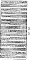
- FIGS. 2A - 2C exhibit a table showing the various angular positions of the first coupling member 14 relative to the second coupling member 18 with respect to each position of the reference indicators 66, 60.
- the apparatus 10 provides a higher degree of adjustment than the prior art while still providing a repeatable and accurate method of adjustment.
- the spacer 16 may be fabricated from a material having a lesser yielding point than the material utilized to form the serrated teeth 36, 37 on the cylindrical base portions 32 of the first and second coupling members 14, 18.
- the spacer 16 will yield or fail as opposed to the serrated teeth 36, 37 on the first and second coupling members 14, 18 yielding or failing or any other portions of the first and second coupling member 14, 18 yielding or failing.
- the yielding or failing of the spacer 16 acts as an indicator that an overload condition has occurred.
- the spacer 16 yields or fails only the spacer 16 need be replaced as opposed to either one or both of the first and second coupling members 14, 18. This reduces the replacement cost of the apparatus 10 thereby increasing the efficiency of the process when utilizing the apparatus 10.
- the second coupling member 18 may first be connected to the master boom 19 by loosening the threaded fastener 31 on the second coupling member 18 and placing the master boom 19 through the semi-circular clamps 20, 22. The threaded fastener 31 is then tightened to secure the second coupling member 18 to the master boom 19. The threaded fastener 31 is loosened to the point of where the spacer 16 may be rotated relative to the first and second coupling members 14, 18. The exact position of the first coupling member 14 relative to the second coupling member 18 may be determined by referencing the chart shown in FIGS. 2A - 2C.
- the spacer 16 When the position is determined, the spacer 16 is rotated such that the reference indicator 68 on the second coupling member 18 is aligned with the appropriate number 64 on the second side 44 of the spacer 16. A first coupling member 14 is then rotated until the reference indicator 66 is aligned with the appropriate letter 59 on the first side 40 of the spacer 16.
- the serrated teeth 36, 3 7, 46, 48 are placed in proper mating engagement, the splined boom rod 15 is placed between the semi-circular clamps 20, 22, and the threaded fastener 31 is tightened. The apparatus 10 is then ready for use.
Landscapes
- Engineering & Computer Science (AREA)
- General Engineering & Computer Science (AREA)
- Mechanical Engineering (AREA)
- Mutual Connection Of Rods And Tubes (AREA)
- Insertion Pins And Rivets (AREA)
Applications Claiming Priority (2)
| Application Number | Priority Date | Filing Date | Title |
|---|---|---|---|
| US68630205P | 2005-06-01 | 2005-06-01 | |
| US11/416,897 US20060285915A1 (en) | 2005-06-01 | 2006-05-04 | Apparatus for incrementally adjusting a modular tooling coupling |
Publications (2)
| Publication Number | Publication Date |
|---|---|
| EP1729054A2 true EP1729054A2 (de) | 2006-12-06 |
| EP1729054A3 EP1729054A3 (de) | 2007-05-16 |
Family
ID=36933495
Family Applications (1)
| Application Number | Title | Priority Date | Filing Date |
|---|---|---|---|
| EP06090092A Withdrawn EP1729054A3 (de) | 2005-06-01 | 2006-05-30 | Vorrichtung zur schrittweisen Einstellung einer modularen Werkzeugkupplung |
Country Status (2)
| Country | Link |
|---|---|
| US (1) | US20060285915A1 (de) |
| EP (1) | EP1729054A3 (de) |
Cited By (3)
| Publication number | Priority date | Publication date | Assignee | Title |
|---|---|---|---|---|
| WO2012109351A1 (en) * | 2011-02-08 | 2012-08-16 | Norgren Automation Solutions, Inc. | Modular tooling apparatus having serrated teeth for orbital and linear adjustment |
| US9095946B2 (en) | 2011-02-08 | 2015-08-04 | Norgren Automation Solutions, Llc | Modular tooling apparatus having serrated teeth for orbital and linear adjustment |
| US11879578B2 (en) * | 2021-12-28 | 2024-01-23 | Lear Corporation | Adjustable cable guide for a flat cable |
Families Citing this family (22)
| Publication number | Priority date | Publication date | Assignee | Title |
|---|---|---|---|---|
| DE102011000205B4 (de) | 2011-01-18 | 2014-07-17 | Illinois Tool Works Inc. | Vorrichtung und Verfahren zum Reffen eines Schlauchfolienabschnitts |
| DE102011075451B4 (de) | 2011-05-06 | 2014-05-08 | Illinois Tool Works Inc. | Verfahren und Vorrichtung zum Aufreffen eines Schlauchfolienabschnitts auf die Refffinger einer Verpackungsanlage |
| FI124180B (fi) * | 2011-09-30 | 2014-04-15 | Illinois Tool Works | Menetelmä käärintäkoneen kuljetustilaan saattamiseksi sekä käärintäkone |
| US9267537B2 (en) * | 2012-04-06 | 2016-02-23 | Koninklijke Philips N.V. | Universal tiltable luminaire support |
| FI125661B (en) | 2012-09-07 | 2015-12-31 | Signode Int Ip Holdings Llc | Method and apparatus for positioning corner guards on a load |
| ES2546857T3 (es) * | 2013-03-15 | 2015-09-29 | Univer S.P.A. | Unión de dos piezas adaptadoras de un dispositivo de soporte de estructura modular |
| US9701009B2 (en) * | 2013-06-13 | 2017-07-11 | The Wooster Brush Company | Tool holder |
| US9808929B2 (en) * | 2013-06-13 | 2017-11-07 | The Wooster Brush Company | Tool holder |
| TWI539819B (zh) * | 2013-09-30 | 2016-06-21 | 鴻海精密工業股份有限公司 | 承載裝置 |
| FI125411B (en) | 2013-10-31 | 2015-10-15 | Signode Internat Ip Holdings Llc | Method and Attachment Device for Attaching the End of a Wrapping Film Web to a Wrapping Machine, and a Wrapping Machine |
| EP2937619B1 (de) * | 2014-04-24 | 2017-03-15 | Ondal Medical Systems GmbH | Drehbare Verbindung mit Drehwinkelbegrenzung |
| US10247352B2 (en) | 2014-04-24 | 2019-04-02 | Ondal Medical Systems Gmbh | Rotatable connection with a rotational angle limitation |
| EP2937618B1 (de) | 2014-04-24 | 2017-09-06 | Ondal Medical Systems GmbH | Drehbare Verbindung mit Drehwinkelbegrenzung |
| EP2937617B1 (de) | 2014-04-24 | 2017-03-01 | Ondal Medical Systems GmbH | Drehbare Verbindung mit Drehwinkelbegrenzung |
| DE102014106365B4 (de) | 2014-05-07 | 2017-06-14 | Lachenmeier Aps | Verpackungsverfahren zum Verpacken eines Gutes |
| DE102015101489A1 (de) | 2015-02-02 | 2016-08-04 | Signode Industrial Group Llc | Verpackungsvorrichtung und Verfahren zum Betrieb derselben |
| US9909538B2 (en) * | 2015-12-09 | 2018-03-06 | Ford Global Technologies, Llc | Vapor blocking valve mounting system |
| US9949565B1 (en) * | 2017-06-15 | 2018-04-24 | Miniwiz Co., Ltd. | Supporting assembly and furniture comprising the same |
| CN108317364A (zh) * | 2018-03-07 | 2018-07-24 | 浙江大华技术股份有限公司 | 一种枪型摄像机支架、枪型摄像机 |
| US11624476B2 (en) * | 2019-04-09 | 2023-04-11 | Tech Rim Standards, LLC | Enclosed pivot unit |
| US20220065395A1 (en) * | 2020-09-02 | 2022-03-03 | Hitachi Cable America Inc. | Orientation Block Assembly |
| US12055180B2 (en) * | 2021-02-12 | 2024-08-06 | Really Right Stuff, Llc | Ball head with anti-rotation self-aligning interface |
Family Cites Families (15)
| Publication number | Priority date | Publication date | Assignee | Title |
|---|---|---|---|---|
| NL29202C (de) * | 1900-01-01 | |||
| US679058A (en) * | 1900-12-24 | 1901-07-23 | George Egbert Mellen | Tripod-stay. |
| US1706215A (en) * | 1926-01-26 | 1929-03-19 | American Safety Device Co | Adjustable coupling means |
| BE793655A (fr) * | 1972-01-10 | 1973-07-04 | Newbould Richard J | Mecanisme diviseur |
| US4186905A (en) * | 1975-06-09 | 1980-02-05 | Dominion Auto Accessories Limited | Retractable truck mirror |
| DE2619200A1 (de) * | 1976-04-30 | 1977-11-10 | Kinski Ernst | Vorrichtung zum beliebigen kuppeln von stahlrohren |
| AU531188B2 (en) * | 1978-10-30 | 1983-08-11 | Hewson, A.J. | Clamp movable in several directions |
| JPS5771758A (en) * | 1980-10-16 | 1982-05-04 | Mitsui Eng & Shipbuild Co Ltd | Angle dividing apparatus for machine tool |
| US4982732A (en) * | 1990-02-06 | 1991-01-08 | Orthopedic Technology, Inc. | Orthopedic rehabilitation knee brace |
| US5133553A (en) * | 1991-02-14 | 1992-07-28 | Divnick Stevan M | Adjustable golf club |
| US5123768A (en) * | 1991-08-06 | 1992-06-23 | Franklin Ronald D | Articulating positioning device for tools |
| FR2717756B1 (fr) * | 1994-03-23 | 1996-05-15 | Journee Paul Sa | Essuie-glace de véhicule automobile comportant des moyens d'orientation de la tête d'entraînement. |
| US5551745A (en) * | 1995-04-04 | 1996-09-03 | Huang; Ming T. | Adjusting device for a hood of a toy stroller |
| US5538245A (en) * | 1995-06-23 | 1996-07-23 | Moore; Donald D. | Golf club with adjustable head |
| ES2212764T3 (es) * | 1999-12-13 | 2004-08-01 | Norgren Automotive Inc. | Aparato de acoplamiento de elementos de utillaje. |
-
2006
- 2006-05-04 US US11/416,897 patent/US20060285915A1/en not_active Abandoned
- 2006-05-30 EP EP06090092A patent/EP1729054A3/de not_active Withdrawn
Cited By (6)
| Publication number | Priority date | Publication date | Assignee | Title |
|---|---|---|---|---|
| WO2012109351A1 (en) * | 2011-02-08 | 2012-08-16 | Norgren Automation Solutions, Inc. | Modular tooling apparatus having serrated teeth for orbital and linear adjustment |
| JP2014511282A (ja) * | 2011-02-08 | 2014-05-15 | ノルグレン オートメーション ソーリューションズ エルエルシー | 軌道及び線形の調整のためのギザギザの歯を有するモジュラ工具装置 |
| US9095946B2 (en) | 2011-02-08 | 2015-08-04 | Norgren Automation Solutions, Llc | Modular tooling apparatus having serrated teeth for orbital and linear adjustment |
| US9395032B2 (en) | 2011-02-08 | 2016-07-19 | Norgren Automation Solutions, Llc | Modular tooling apparatus having serrated teeth for orbital and linear adjustment |
| US9429187B2 (en) | 2011-02-08 | 2016-08-30 | Norgren Automation Solutions, Llc | Modular tooling apparatus having serrated teeth for orbital and linear adjustment |
| US11879578B2 (en) * | 2021-12-28 | 2024-01-23 | Lear Corporation | Adjustable cable guide for a flat cable |
Also Published As
| Publication number | Publication date |
|---|---|
| EP1729054A3 (de) | 2007-05-16 |
| US20060285915A1 (en) | 2006-12-21 |
Similar Documents
| Publication | Publication Date | Title |
|---|---|---|
| EP1729054A2 (de) | Vorrichtung zur schrittweisen Einstellung einer modularen Werkzeugkupplung | |
| EP2673120B1 (de) | Modulare werkzeugvorrichtung mit gezackten zähnen für orbitale und lineare einstellungen | |
| EP1108945B1 (de) | Modulare Werkzeugkupplungsvorrichtung | |
| US9095946B2 (en) | Modular tooling apparatus having serrated teeth for orbital and linear adjustment | |
| JP2014511282A5 (de) | ||
| US8162557B2 (en) | Multi-axis coupling apparatus for adjustably mounting modular tooling members | |
| DE102006017763B4 (de) | Dünnglasgreifer | |
| EP2002926A1 (de) | Turbinenblatthaltevorrichtung und -verfahren | |
| US10124486B2 (en) | Automatically positionable joints and transfer tooling assemblies including automatically positionable joints | |
| US12202127B2 (en) | Adjustable suction gripper | |
| US20150139774A1 (en) | Rotary chuck | |
| EP2197633B1 (de) | Industrierobotervorrichtung, industrieroboter und verfahren zur handhabung von objekten | |
| CN111015733A (zh) | 附装机构、机器人装置和附装方法 | |
| AU2018247589B2 (en) | Support assembly for swivellably supporting hydraulic lines | |
| US20080226427A1 (en) | Apparatus for accurately positioning and supporting modular tooling | |
| CN206925875U (zh) | 夹持装置及具有该夹持装置的机械手 | |
| US20100156126A1 (en) | Modular shovel for use with an adapter assembly | |
| US4848759A (en) | Holding apparatus | |
| AU2017203317A1 (en) | A Tool Attachment | |
| CN1876338A (zh) | 用于增量调节模块化工具联接器的装置 | |
| JPH036395B2 (de) | ||
| CN213224409U (zh) | 一种弧形瓦片加工夹具 | |
| KR20230024029A (ko) | 각도 조절 가능한 핸들을 구비하는 펜치 | |
| CN115870954A (zh) | 一种工业机器人用可调安装底座 | |
| JPWO2024247095A5 (de) |
Legal Events
| Date | Code | Title | Description |
|---|---|---|---|
| PUAI | Public reference made under article 153(3) epc to a published international application that has entered the european phase |
Free format text: ORIGINAL CODE: 0009012 |
|
| 17P | Request for examination filed |
Effective date: 20060530 |
|
| AK | Designated contracting states |
Kind code of ref document: A2 Designated state(s): AT BE BG CH CY CZ DE DK EE ES FI FR GB GR HU IE IS IT LI LT LU LV MC NL PL PT RO SE SI SK TR |
|
| AX | Request for extension of the european patent |
Extension state: AL BA HR MK YU |
|
| PUAL | Search report despatched |
Free format text: ORIGINAL CODE: 0009013 |
|
| AK | Designated contracting states |
Kind code of ref document: A3 Designated state(s): AT BE BG CH CY CZ DE DK EE ES FI FR GB GR HU IE IS IT LI LT LU LV MC NL PL PT RO SE SI SK TR |
|
| AX | Request for extension of the european patent |
Extension state: AL BA HR MK YU |
|
| 17Q | First examination report despatched |
Effective date: 20071228 |
|
| AKX | Designation fees paid |
Designated state(s): AT BE BG CH CY CZ DE DK EE ES FI FR GB GR HU IE IS IT LI LT LU LV MC NL PL PT RO SE SI SK TR |
|
| STAA | Information on the status of an ep patent application or granted ep patent |
Free format text: STATUS: THE APPLICATION IS DEEMED TO BE WITHDRAWN |
|
| 18D | Application deemed to be withdrawn |
Effective date: 20080508 |