EP1729073A1 - Système de radiateur avec plusieures possibilités de montage - Google Patents
Système de radiateur avec plusieures possibilités de montage Download PDFInfo
- Publication number
- EP1729073A1 EP1729073A1 EP05012097A EP05012097A EP1729073A1 EP 1729073 A1 EP1729073 A1 EP 1729073A1 EP 05012097 A EP05012097 A EP 05012097A EP 05012097 A EP05012097 A EP 05012097A EP 1729073 A1 EP1729073 A1 EP 1729073A1
- Authority
- EP
- European Patent Office
- Prior art keywords
- radiator
- overflow
- radiator system
- connection
- plug
- Prior art date
- Legal status (The legal status is an assumption and is not a legal conclusion. Google has not performed a legal analysis and makes no representation as to the accuracy of the status listed.)
- Granted
Links
- 239000012530 fluid Substances 0.000 claims abstract description 14
- 238000010438 heat treatment Methods 0.000 claims description 10
- 238000009434 installation Methods 0.000 claims description 3
- 238000000034 method Methods 0.000 claims description 3
- 238000007789 sealing Methods 0.000 description 27
- 101100390736 Danio rerio fign gene Proteins 0.000 description 9
- 101100390738 Mus musculus Fign gene Proteins 0.000 description 9
- 238000003780 insertion Methods 0.000 description 6
- 230000037431 insertion Effects 0.000 description 6
- 230000007704 transition Effects 0.000 description 3
- 238000013022 venting Methods 0.000 description 3
- 238000003466 welding Methods 0.000 description 3
- 238000004026 adhesive bonding Methods 0.000 description 2
- 238000010276 construction Methods 0.000 description 2
Images


Classifications
-
- F—MECHANICAL ENGINEERING; LIGHTING; HEATING; WEAPONS; BLASTING
- F24—HEATING; RANGES; VENTILATING
- F24D—DOMESTIC- OR SPACE-HEATING SYSTEMS, e.g. CENTRAL HEATING SYSTEMS; DOMESTIC HOT-WATER SUPPLY SYSTEMS; ELEMENTS OR COMPONENTS THEREFOR
- F24D19/00—Details
- F24D19/0002—Means for connecting central heating radiators to circulation pipes
-
- F—MECHANICAL ENGINEERING; LIGHTING; HEATING; WEAPONS; BLASTING
- F24—HEATING; RANGES; VENTILATING
- F24D—DOMESTIC- OR SPACE-HEATING SYSTEMS, e.g. CENTRAL HEATING SYSTEMS; DOMESTIC HOT-WATER SUPPLY SYSTEMS; ELEMENTS OR COMPONENTS THEREFOR
- F24D19/00—Details
- F24D19/0002—Means for connecting central heating radiators to circulation pipes
- F24D19/0026—Places of the inlet on the radiator
- F24D19/0029—Places of the inlet on the radiator on a top corner
-
- F—MECHANICAL ENGINEERING; LIGHTING; HEATING; WEAPONS; BLASTING
- F24—HEATING; RANGES; VENTILATING
- F24D—DOMESTIC- OR SPACE-HEATING SYSTEMS, e.g. CENTRAL HEATING SYSTEMS; DOMESTIC HOT-WATER SUPPLY SYSTEMS; ELEMENTS OR COMPONENTS THEREFOR
- F24D19/00—Details
- F24D19/0002—Means for connecting central heating radiators to circulation pipes
- F24D19/0026—Places of the inlet on the radiator
- F24D19/0034—Places of the inlet on the radiator on a bottom corner
-
- F—MECHANICAL ENGINEERING; LIGHTING; HEATING; WEAPONS; BLASTING
- F24—HEATING; RANGES; VENTILATING
- F24D—DOMESTIC- OR SPACE-HEATING SYSTEMS, e.g. CENTRAL HEATING SYSTEMS; DOMESTIC HOT-WATER SUPPLY SYSTEMS; ELEMENTS OR COMPONENTS THEREFOR
- F24D19/00—Details
- F24D19/0002—Means for connecting central heating radiators to circulation pipes
- F24D19/0039—Places of the outlet on the radiator
- F24D19/0043—Places of the outlet on the radiator on the opposite top corner
-
- F—MECHANICAL ENGINEERING; LIGHTING; HEATING; WEAPONS; BLASTING
- F24—HEATING; RANGES; VENTILATING
- F24D—DOMESTIC- OR SPACE-HEATING SYSTEMS, e.g. CENTRAL HEATING SYSTEMS; DOMESTIC HOT-WATER SUPPLY SYSTEMS; ELEMENTS OR COMPONENTS THEREFOR
- F24D19/00—Details
- F24D19/0002—Means for connecting central heating radiators to circulation pipes
- F24D19/0039—Places of the outlet on the radiator
- F24D19/0046—Places of the outlet on the radiator on the top on the same side
-
- F—MECHANICAL ENGINEERING; LIGHTING; HEATING; WEAPONS; BLASTING
- F24—HEATING; RANGES; VENTILATING
- F24D—DOMESTIC- OR SPACE-HEATING SYSTEMS, e.g. CENTRAL HEATING SYSTEMS; DOMESTIC HOT-WATER SUPPLY SYSTEMS; ELEMENTS OR COMPONENTS THEREFOR
- F24D19/00—Details
- F24D19/0002—Means for connecting central heating radiators to circulation pipes
- F24D19/0039—Places of the outlet on the radiator
- F24D19/0051—Places of the outlet on the radiator on the bottom on the opposite corner
-
- F—MECHANICAL ENGINEERING; LIGHTING; HEATING; WEAPONS; BLASTING
- F24—HEATING; RANGES; VENTILATING
- F24D—DOMESTIC- OR SPACE-HEATING SYSTEMS, e.g. CENTRAL HEATING SYSTEMS; DOMESTIC HOT-WATER SUPPLY SYSTEMS; ELEMENTS OR COMPONENTS THEREFOR
- F24D19/00—Details
- F24D19/0002—Means for connecting central heating radiators to circulation pipes
- F24D19/0039—Places of the outlet on the radiator
- F24D19/0053—Places of the outlet on the radiator on the bottom on the same side
-
- F—MECHANICAL ENGINEERING; LIGHTING; HEATING; WEAPONS; BLASTING
- F24—HEATING; RANGES; VENTILATING
- F24D—DOMESTIC- OR SPACE-HEATING SYSTEMS, e.g. CENTRAL HEATING SYSTEMS; DOMESTIC HOT-WATER SUPPLY SYSTEMS; ELEMENTS OR COMPONENTS THEREFOR
- F24D19/00—Details
- F24D19/0002—Means for connecting central heating radiators to circulation pipes
- F24D19/0073—Means for changing the flow of the fluid inside a radiator
-
- F—MECHANICAL ENGINEERING; LIGHTING; HEATING; WEAPONS; BLASTING
- F24—HEATING; RANGES; VENTILATING
- F24D—DOMESTIC- OR SPACE-HEATING SYSTEMS, e.g. CENTRAL HEATING SYSTEMS; DOMESTIC HOT-WATER SUPPLY SYSTEMS; ELEMENTS OR COMPONENTS THEREFOR
- F24D19/00—Details
- F24D19/0002—Means for connecting central heating radiators to circulation pipes
- F24D19/0078—Plugs
-
- F—MECHANICAL ENGINEERING; LIGHTING; HEATING; WEAPONS; BLASTING
- F28—HEAT EXCHANGE IN GENERAL
- F28D—HEAT-EXCHANGE APPARATUS, NOT PROVIDED FOR IN ANOTHER SUBCLASS, IN WHICH THE HEAT-EXCHANGE MEDIA DO NOT COME INTO DIRECT CONTACT
- F28D1/00—Heat-exchange apparatus having stationary conduit assemblies for one heat-exchange medium only, the media being in contact with different sides of the conduit wall, in which the other heat-exchange medium is a large body of fluid, e.g. domestic or motor car radiators
- F28D1/02—Heat-exchange apparatus having stationary conduit assemblies for one heat-exchange medium only, the media being in contact with different sides of the conduit wall, in which the other heat-exchange medium is a large body of fluid, e.g. domestic or motor car radiators with heat-exchange conduits immersed in the body of fluid
- F28D1/03—Heat-exchange apparatus having stationary conduit assemblies for one heat-exchange medium only, the media being in contact with different sides of the conduit wall, in which the other heat-exchange medium is a large body of fluid, e.g. domestic or motor car radiators with heat-exchange conduits immersed in the body of fluid with plate-like or laminated conduits
- F28D1/0308—Heat-exchange apparatus having stationary conduit assemblies for one heat-exchange medium only, the media being in contact with different sides of the conduit wall, in which the other heat-exchange medium is a large body of fluid, e.g. domestic or motor car radiators with heat-exchange conduits immersed in the body of fluid with plate-like or laminated conduits the conduits being formed by paired plates touching each other
- F28D1/0325—Heat-exchange apparatus having stationary conduit assemblies for one heat-exchange medium only, the media being in contact with different sides of the conduit wall, in which the other heat-exchange medium is a large body of fluid, e.g. domestic or motor car radiators with heat-exchange conduits immersed in the body of fluid with plate-like or laminated conduits the conduits being formed by paired plates touching each other the plates having lateral openings therein for circulation of the heat-exchange medium from one conduit to another
- F28D1/0333—Heat-exchange apparatus having stationary conduit assemblies for one heat-exchange medium only, the media being in contact with different sides of the conduit wall, in which the other heat-exchange medium is a large body of fluid, e.g. domestic or motor car radiators with heat-exchange conduits immersed in the body of fluid with plate-like or laminated conduits the conduits being formed by paired plates touching each other the plates having lateral openings therein for circulation of the heat-exchange medium from one conduit to another the plates having integrated connecting members
-
- F—MECHANICAL ENGINEERING; LIGHTING; HEATING; WEAPONS; BLASTING
- F28—HEAT EXCHANGE IN GENERAL
- F28F—DETAILS OF HEAT-EXCHANGE AND HEAT-TRANSFER APPARATUS, OF GENERAL APPLICATION
- F28F9/00—Casings; Header boxes; Auxiliary supports for elements; Auxiliary members within casings
- F28F9/26—Arrangements for connecting different sections of heat-exchange elements, e.g. of radiators
- F28F9/262—Arrangements for connecting different sections of heat-exchange elements, e.g. of radiators for radiators
-
- F—MECHANICAL ENGINEERING; LIGHTING; HEATING; WEAPONS; BLASTING
- F28—HEAT EXCHANGE IN GENERAL
- F28F—DETAILS OF HEAT-EXCHANGE AND HEAT-TRANSFER APPARATUS, OF GENERAL APPLICATION
- F28F2220/00—Closure means, e.g. end caps on header boxes or plugs on conduits
Definitions
- the present invention relates to a radiator system with a radiator comprising a plurality of interconnected members, each member having at its two ends at least two overflow openings which create a fluid connection between adjacent members.
- Those overflow openings which are formed on the arranged on the outside of the radiator end members and open to the outside of the radiator system, are provided with connection fittings and serve as connection openings, where either the Schufluidvorlauf- or return line can be connected.
- at least two members of the radiator at one of its ends comprise at least one further connection opening for selectively connecting the Schufluidvorlauf- or return line.
- the radiator system normally includes six such ports, two of which are located on each side of the radiator system.
- the end user thus has the free choice of which side of the radiator he wants to connect the Schufluidvorlauftechnisch and on which side he Schufluid Weglauf admir.
- the radiator system can be used flexibly. Depending on the choice of the end user, it may be necessary that a certain overflow between an end member and an adjacent member must be fluid-tightly sealed in order to avoid a hydraulic short circuit during operation of the radiator system.
- the corresponding overflow opening is then sealed in a fluid-tight manner by the customer with a sealing system, wherein normally a sealing body of the sealing system in the overflow opening is used and is pressed sealingly against the edge surrounding the overflow opening.
- Such a sealing system is for example in the EP 1 243 887 A1 described.
- This sealing system comprises at least one sealing body, a pressure element and a sealing pin, wherein the sealing body is designed as a sealing ring with a defined passage opening, the sealing pin has an end face and the pressure element comprises at least a flat area with an opposite the end face of the Abdichtchanes enlarged diameter.
- the pressure element is arranged between the sealing ring and the sealing pin, the sealing pin is introduced through an opening opposite the overflow opening to be sealed, and an axially acting force is applied to the sealing pin in the direction of the overflow opening to be sealed.
- the radiator system comprises a radiator having a plurality of interconnected members, wherein the members are preferably formed in a columnar shape.
- Each member has at least two overflow openings at its two ends, which create a fluid connection between adjacent members.
- Those overflow openings which are connected to an end member of the Radiator are formed and open to a free end of the radiator can be used as connection openings for connecting a Walkerfluidvorlauf- or return line.
- At least two links further include at one end thereof at least one further port which may also be used to connect a heating fluid supply or return line.
- the radiator system according to the invention further comprises a plurality of fastening aids, which are each provided at an overflow opening between an end member and an adjacent member, and a plug member which is positionable on a mounting aid and with the aid of which the corresponding overflow is substantially fluid-tight closed.
- a closure of such overflow opening may be required to prevent a hydraulic short circuit during operation of the radiator system according to the invention, depending on which end overflow or at which connection opening the Schufluidvorlauf- and return line to be connected.
- a plurality of fastening aids are provided, which are each pre-assembled on the radiator system.
- the fastening aids and the plug element are designed such that the plug element can be positioned by the installer in a simple manner at the customer either on one of the overflow opening provided with a fastening aid. Due to the fact that the plug element can be optionally arranged at different overflow openings, different connection combinations for the Schufluidvorlauf- and return line can be easily realized in which a corresponding sealing an overflow is required. Since the mounting aids are pre-assembled, the plug element can be easily used on site during installation of the radiator system at the customer of the installer in the appropriate overflow.
- the fastening aids are perforated disks into which either a plug element can be inserted in a substantially fluid-tight manner.
- the perforated disc may comprise an internal thread into which an external thread of the plug element can be screwed.
- a seal is advantageously fluid-tight positioned between the plug member and perforated disc, for example, a set around the plug member sealing ring, which is then clamped fluid-tight between the perforated disc and a stopper of the plug member.
- the plug member is advantageously formed substantially rod-shaped to improve the handling of the plug member during insertion into an overflow.
- a rod-shaped plug element can be kept easier during the insertion process through an end overflow opening in the corresponding adjacent overflow.
- the plug element preferably has a portion on which an assembly tool can engage.
- This section has, for example, a recess into which a screwdriver can engage, leading edges for a wrench or the like.
- the plug element is advantageously designed such that it is completely retractable in the interior of the radiator system in the state in which it closes an overflow opening between an end member and an adjacently arranged member.
- conventional closure elements can be used to fluid-tightly close the end overflow after insertion of the plug member in the mounting aid.
- Such conventional closure elements can then also for closing all remaining, not yet closed end overflow, to which no Schufluidvorlauf- or return line is connected, can be used.
- a valve element may also be employed.
- the radiator system according to the invention with the preassembled mounting aids has the advantage that with the aid of a plug element, a plurality of conventional closure elements and possibly a valve element substantially any connection variants of Schufluidvorlauf- and return line are possible, which can be realized on site at the end user by the installer are.
- the number of components required for assembly can be reduced to a minimum.
- the sale of Radiator systems can be completely ex-warehouse, as no factory adjustment of the radiator systems to customer requirements is required.
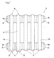
- Fig. 1 is a front view of a conventional radiator 10 belonging to the prior art.
- the radiator 10 comprises a plurality of members 12 which are arranged in series next to each other.
- Each member has two hub-like ends 14 and 16, in each of which two opposing circular overflow openings 18 are formed, which are not shown in Fig. 1.
- the members 12 are connected to each other liquid-tight. This can, for example, by welding, screwing or the like.
- an overflow opening 18 remains in the connection area, through which a fluid exchange between the individual members 12 can take place.
- end-side members 12 a and 12 b which are arranged on the outer sides of the radiator 10, remain end-overflow openings 18 a to 18 d, which point to the outside of the radiator 10 and make no fluid connection between two adjacent members 12.
- connecting fittings 20 are arranged, to which either a Schufluidvorlauf- or return line is connected.
- each at the lower end each have a further connection opening 22 is provided.
- this connection openings 22 also a Rothfluidvorlauf- or return line can also be connected optionally.
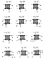
- the Fign. 2A to 2L are schematic views showing the possible connection variants of a Schufluidvorlauf- and return line to the radiator 10 shown in Fig. 1.
- the Schufluidvorlauf and return is shown by arrows.
- a closure element may also be a suitable valve element which regulates the flow of the heating medium through the radiator 10, or a closure element with a E: itlmodalung for venting the radiator 10 are arranged.
- connection variant shown in Fig. 2A it is not necessary to close an overflow, since in this connection variant no hydraulic short circuit is to be feared.
- an overflow port can be closed with various known sealing systems.
- these known sealing systems are designed such that they can be installed only at the factory, since the installation is relatively expensive.
- this has the consequence that the known radiators are not available directly from stock, as soon as the customer is selected a connection variant in which an overflow must be closed because before delivery to the customer, the appropriate sealing system must still be mounted. Accordingly, the order processing in this regard is quite problematic.
- FIG. 3 is a cross-sectional view of one embodiment of a radiator 30 of the radiator system according to the invention.
- the radiator 30 has substantially the same construction as the conventional radiator 10 shown in FIG.
- the radiator 30 according to the invention comprises a plurality of members 12 which are arranged in series next to each other and connected to each other.
- Each member 12 has two hub-like ends 14 and 16, in which two opposing circular overflow openings 18 are formed. About these overflow openings 18, the juxtaposed members 12 are fluidly interconnected.
- the connection of the individual members 12 can be done by welding, gluing, screwing or the like.
- the end-side members 12a and 12b have at their hub-like ends 14 and 16 each have an overflow 18a, b, c and d, which opens to the outside of the radiator 30 and does not serve as a fluid connection between two members 12.
- a connection fitting 20 is arranged, to which a Schufluidvorlauf- or return line is selectively connectable, which will not be explained in detail at this point.
- the end-side member 12a and the adjacently arranged member 12 each comprise at its hub-like end 14, a further connection opening 22, to which also optionally a Schufluidvorlauf- or return line is connected.
- the radiator 30 according to the invention corresponds to the conventional radiator 10 shown in FIG. 1.
- radiator 30 Unlike the conventional radiator 10 is in the radiator 30 according to the invention at the two overflow openings 18, which connect the end-side member 12 a and the adjacently disposed member 12 fluidly together, in each case a mounting aid 32 pre-assembled.
- This attachment aid 32 is fixedly attached to one of the two members 12a or 12, in Fig. 3 at the end-side member 12a.
- the attachment can be done by gluing, welding, screws or the like, wherein the transition between the mounting aid 32 and the corresponding member 12 or 12a is formed fluid-tight.
- the fastening aids 32 are used for fastening a plug element or a valve element which is inserted during assembly of the radiator 30 at the end user by the installer through the end overflow opening 18 a or 18 b in the radiator 30 and inserted into the corresponding mounting aid 32.
- FIG. 4 is a cross-sectional view showing an enlarged view of one of the attachment aids 32 shown in FIG. 3.
- the attachment aid 32 is presently formed hole plate similar and bent along its inner diameter to form a hollow cylindrical projection 34 away.
- the projection 34 includes an internal thread 36 into which a corresponding external thread of a plug element or a valve element can be screwed, which is explained in more detail below.
- Fig. 5 is a partially sectioned front view of one embodiment of a plug element 38 of the radiator system according to the invention.
- the plug member 38 is substantially rod-shaped and has a circular cross-section.
- the one end, with which the plug member 38 is insertable into the mounting aid 32, has a chamfer 40, which facilitates the insertion of the plug member 38 into the cylindrical opening of the mounting aid 32.
- a slot 42 is provided for receiving a screwdriver.
- the plug member 38 Adjacent to the chamfer 40, the plug member 38 includes an external thread 44 that can be brought into engagement with the internal thread 36 of the mounting aid 32.
- a shoulder 46 connects, which serves as a stop when inserting the plug member 38 in the mounting aid 32.
- the shoulder 46 includes an annular recess 48 in which a sealing ring can be arranged to fluid-tightly close the transition between the plug member 38 and the mounting aid 32.
- Fig. 6 is a partially cutaway front view of one embodiment of a valve element of the radiator system according to the present invention.
- the valve element 50 does not differ in its function from conventional valve elements, which is why will not be discussed in detail below.
- the valve element 50 is substantially rod-shaped and has a circular cross-section.
- a hollow cylindrical seal 54 is arranged, which projects beyond the free end 52 of the plug element 38 on one side.
- the other end of the hollow cylindrical seal 54 abuts a shoulder-shaped stop 56, which prevents movement of the hollow cylindrical seal 54 in the direction of the other free end 58 of the plug member 38.
- the hollow cylindrical seal 54 is in the state in which the valve element 50 is inserted into the heating element 30 according to the invention, pressed under the action of an axial force against a mounting aid 32, whereby a fluid-tight press connection between the valve element 50 and the mounting aid 32 is generated.
- the valve element 50 comprises an external thread 60 which can be screwed into a corresponding internal thread of a connection fitting 20 of the radiator 30 according to the invention.
- the valve member 50 For sealing the valve element 50 relative to the connection fitting 20th the valve member 50 includes near its free end 58 a shoulder 62 which has an annular recess 64 in the direction of the free end 52 of the valve element 50 into which a sealing ring 66 can be inserted.
- Fig. 7 is a side view showing an embodiment of a shutter member 70 of the radiator system according to the present invention.
- the closure member 70 is substantially cylindrical and comprises at one end a helical portion 72 on which a wrench can attack, next to a stop 74 in the form of a paragraph and a subsequent to the stop 74 and to the other end of the closure element 70th extending external thread 76 which is screwed into a corresponding internal thread of a connection fitting 20 of the radiator 30 according to the invention.
- Fig. 7 is a side view of another embodiment of a closure element 80 with integrated vent.
- the closure member 80 comprises a helical portion 72, a stop 74 and an external thread 76.
- the closure member 80 comprises a venting device 82, the structure and function of which are already known in the art and are therefore not further explained.
- the in Figs. 3 to 8 illustrated embodiment of the radiator system according to the invention thus comprises, briefly summarized, the radiator 30 according to the invention, at the end overflow openings 18a to d and at its connection openings 22 each connection fittings 20 and arranged at the overflow openings 18 which the fluid connection between the end-side member 12a and produce the corresponding adjacent member 12, according to the invention mounting aids 32 are pre-assembled.
- this embodiment of the radiator system comprises a plug element 38 and a valve element 50, which can be used in each case in one of the preassembled mounting aids 32, wherein the transition between the plug member 38 and between the valve member 50 and the mounting aid 32 is closed fluid-tight in the inserted state , Finally, closure elements 70 and / or closure elements 80 provided with which the connection fittings 20 are optionally closed fluid-tight.
- FIG. 9 is an enlarged fragmentary cross-sectional view of the embodiment of the heater 30 of the present invention shown in FIG. 3, showing the plug member 38 shown in FIG. 5 when installed.
- the plug element 38 is arranged as follows: The plug element 38 is guided through the end overflow opening 18b of the radiator 30 and inserted with the chamfer 40 ahead through the hollow cylindrical projection 34 of the mounting aid 32 until the external thread 44 of the plug member 38 with the internal thread 36 of the mounting aid 32 comes into engagement.
- a screwdriver is attached to the slot 42 of the plug element 38 and the external thread 44 of the plug member 38 is screwed into the internal thread 36 of the mounting aid 32, wherein during the threaded engagement an annular seal 86 which is arranged in the annular recess 48 of the plug member 38, between the Paragraph 46 of the plug member 38 and the mounting aid 32 is compressed to produce in this way a fluid-tight connection between the mounting aid 32 and the plug member 38.
- the external thread 76 of the closure element 70 is screwed into the corresponding internal thread of the connection fitting 20 and thus the end-side overflow 18b closed fluid-tight.
- valve element 50 is guided with its free end 52 ahead through the opening of the connection fitting 20 until the external thread 60 of the valve element 50 engages with the corresponding internal thread of the connection fitting 20.
- the valve member 50 is further threaded into the port fitting 20 creating an axial force which, supported by the stop 56, presses the hollow cylindrical seal 54 of the valve member 50 against the mounting aid 32 creating a fluid tight connection between the mounting aid 32 and the valve member 50.
- Fig. 11 is a front cross-sectional view of the radiator system according to the invention showing a particular connection variant.
- the radiator 30 according to the invention is shown as shown in Fig. 3 delivered pre-assembled to the end user, in which the radiator system according to the invention to be installed.
- a connection variant is now to be realized in which Bankfluidvor- and return line should be made on opposite sides of the radiator 30 of the invention at the same height, in Fig. 11 so bottom left and bottom right, which is shown by the corresponding arrows.
- the lower overflow opening 18 In order to prevent the heating fluid from flowing directly from the end-side overflow opening 18b through the lower hub-like ends 14 to the end-side overflow opening 18d, ie to prevent a hydraulic short circuit, the lower overflow opening 18 must be closed in a fluid-tight manner between the two connection openings 22. Accordingly, in this overflow opening 18, as shown in Fig. 9, the plug member 38 is used. Furthermore, the two connection openings 22 and the end-side overflow opening 18a are closed fluid-tight with corresponding closure elements 70 by the closure elements are screwed into the respective connection fittings 20. In the connection fitting 20, which is arranged at the end overflow opening 18 c, a closure element 80 is provided with integrated vent. Due to the arrangement of the plug member 38, the heating element 30 according to the invention is uniformly flowed through by the heating fluid, which is shown schematically by the arrows.
- Fig. 12 is a cross-sectional view of the radiator system according to the invention, showing a further connection variant.
- the Schufluidvor- and return line are realized side by side at the connection openings 22.
- the plug element 38 is again inserted into the lower fastening aid 32 between the two connection openings 22.
- a valve element 50 is disposed on the upper attachment aid 32.
- the connection fittings 20 at the end-side overflow openings 18b and 18d are fluid-tight with closure elements 70 locked.
- a closure element 80 is provided with integrated vent.
- the Fign. 13A to 13L are cross-sectional views of the radiator system according to the invention showing the possible connection variants.
- the in this Fign. shown connection options correspond to those connection options, which are shown in Fig. 2 for a conventional radiator.
- the main advantage of the radiator system according to the invention is that all of the in Figs. 13A to 13L connection variants shown by the installer in the assembly of the radiator system according to the invention at the end user can be realized without a workshop-side adjustment of the heating system is required in relation to the customer.
- the radiator system according to the invention comprises only a few components, namely the radiator 30 with the preassembled connection fittings 20, connection openings 22 and fastening aids 32, a plug element 38, a valve element 50 as desired, a corresponding number of closure elements 70 and, if desired, a closure element 80.
- valve elements 50 are shown in the Fign. 13A to L. It should be understood, however, that a closure member 70 may be replaced with a corresponding valve member 50 as desired.
- the heating element 30, the connection fittings 20, the connection opening 22, the mounting aid 32, the plug element 38, the Valve element 50, the closure element 70 and the closure element 80 be configured differently than it is in the Fign. is shown.
Landscapes
- Engineering & Computer Science (AREA)
- Physics & Mathematics (AREA)
- Thermal Sciences (AREA)
- Mechanical Engineering (AREA)
- General Engineering & Computer Science (AREA)
- Chemical & Material Sciences (AREA)
- Combustion & Propulsion (AREA)
- Steam Or Hot-Water Central Heating Systems (AREA)
Priority Applications (2)
| Application Number | Priority Date | Filing Date | Title |
|---|---|---|---|
| PL05012097T PL1729073T3 (pl) | 2005-06-04 | 2005-06-04 | Układ grzejnika z możliwością wielokrotnego przyłączenia |
| EP05012097.1A EP1729073B1 (fr) | 2005-06-04 | 2005-06-04 | Système de radiateur avec plusieures possibilités de montage |
Applications Claiming Priority (1)
| Application Number | Priority Date | Filing Date | Title |
|---|---|---|---|
| EP05012097.1A EP1729073B1 (fr) | 2005-06-04 | 2005-06-04 | Système de radiateur avec plusieures possibilités de montage |
Publications (2)
| Publication Number | Publication Date |
|---|---|
| EP1729073A1 true EP1729073A1 (fr) | 2006-12-06 |
| EP1729073B1 EP1729073B1 (fr) | 2017-08-09 |
Family
ID=35134764
Family Applications (1)
| Application Number | Title | Priority Date | Filing Date |
|---|---|---|---|
| EP05012097.1A Expired - Lifetime EP1729073B1 (fr) | 2005-06-04 | 2005-06-04 | Système de radiateur avec plusieures possibilités de montage |
Country Status (2)
| Country | Link |
|---|---|
| EP (1) | EP1729073B1 (fr) |
| PL (1) | PL1729073T3 (fr) |
Cited By (6)
| Publication number | Priority date | Publication date | Assignee | Title |
|---|---|---|---|---|
| WO2010021003A1 (fr) * | 2008-08-20 | 2010-02-25 | Omec Dl Codenotti & C. S.N.C. | Kit permettant de fermer le moyeu d’un élément terminal d’un radiateur |
| RU2396492C1 (ru) * | 2008-03-08 | 2010-08-10 | Данфосс А/С | Секционный радиатор |
| DE102009011150A1 (de) | 2009-02-28 | 2010-09-09 | Danfoss A/S | Gliederheizkörpertrennelement und Gliederheizkörper |
| EP2098801A3 (fr) * | 2008-03-07 | 2013-09-25 | Zehnder Verkaufs- und Verwaltungs AG | Radiateur ayant plusieurs possibilités de raccordement |
| WO2015136500A1 (fr) * | 2014-03-14 | 2015-09-17 | Fondital S.P.A. | Kit de raccordement pour raccorder un radiateur de chauffage à un système de plomberie |
| IT202100028895A1 (it) * | 2021-11-15 | 2023-05-15 | Cordivari S R L | Kit di ghiera flottante per testine di radiatore da interni, testina per radiatore e relativo processo. |
Citations (5)
| Publication number | Priority date | Publication date | Assignee | Title |
|---|---|---|---|---|
| DE1679429A1 (de) * | 1967-04-29 | 1972-03-16 | Schaefer Kg Fritz | Umlenkverschluss fuer Heizungsradiatoren |
| DE29502860U1 (de) * | 1995-02-21 | 1995-04-06 | HKF Heizkörperfertigung Meiningen GmbH, 98617 Meiningen | Röhrenradiator |
| EP0735338A1 (fr) * | 1995-03-25 | 1996-10-02 | Zehnder Verkaufs- und Verwaltungs AG | Radiateur |
| DE19818209A1 (de) * | 1997-04-26 | 1998-11-05 | Siegfried Von Der Heyden | Universal-Gliederheizkörper |
| EP1243887A1 (fr) | 2001-03-21 | 2002-09-25 | Zehnder Verkaufs- und Verwaltungs AG | Système d'étanchéité pour radiateur |
-
2005
- 2005-06-04 EP EP05012097.1A patent/EP1729073B1/fr not_active Expired - Lifetime
- 2005-06-04 PL PL05012097T patent/PL1729073T3/pl unknown
Patent Citations (5)
| Publication number | Priority date | Publication date | Assignee | Title |
|---|---|---|---|---|
| DE1679429A1 (de) * | 1967-04-29 | 1972-03-16 | Schaefer Kg Fritz | Umlenkverschluss fuer Heizungsradiatoren |
| DE29502860U1 (de) * | 1995-02-21 | 1995-04-06 | HKF Heizkörperfertigung Meiningen GmbH, 98617 Meiningen | Röhrenradiator |
| EP0735338A1 (fr) * | 1995-03-25 | 1996-10-02 | Zehnder Verkaufs- und Verwaltungs AG | Radiateur |
| DE19818209A1 (de) * | 1997-04-26 | 1998-11-05 | Siegfried Von Der Heyden | Universal-Gliederheizkörper |
| EP1243887A1 (fr) | 2001-03-21 | 2002-09-25 | Zehnder Verkaufs- und Verwaltungs AG | Système d'étanchéité pour radiateur |
Cited By (8)
| Publication number | Priority date | Publication date | Assignee | Title |
|---|---|---|---|---|
| EP2098801A3 (fr) * | 2008-03-07 | 2013-09-25 | Zehnder Verkaufs- und Verwaltungs AG | Radiateur ayant plusieurs possibilités de raccordement |
| RU2396492C1 (ru) * | 2008-03-08 | 2010-08-10 | Данфосс А/С | Секционный радиатор |
| WO2010021003A1 (fr) * | 2008-08-20 | 2010-02-25 | Omec Dl Codenotti & C. S.N.C. | Kit permettant de fermer le moyeu d’un élément terminal d’un radiateur |
| DE102009011150A1 (de) | 2009-02-28 | 2010-09-09 | Danfoss A/S | Gliederheizkörpertrennelement und Gliederheizkörper |
| RU2427777C1 (ru) * | 2009-02-28 | 2011-08-27 | Данфосс А/С | Разделительный элемент для секционного радиатора и секционный радиатор |
| DE102009011150B4 (de) | 2009-02-28 | 2020-08-06 | Danfoss A/S | Gliederheizkörpertrennelement und Gliederheizkörper |
| WO2015136500A1 (fr) * | 2014-03-14 | 2015-09-17 | Fondital S.P.A. | Kit de raccordement pour raccorder un radiateur de chauffage à un système de plomberie |
| IT202100028895A1 (it) * | 2021-11-15 | 2023-05-15 | Cordivari S R L | Kit di ghiera flottante per testine di radiatore da interni, testina per radiatore e relativo processo. |
Also Published As
| Publication number | Publication date |
|---|---|
| PL1729073T3 (pl) | 2018-01-31 |
| EP1729073B1 (fr) | 2017-08-09 |
Similar Documents
| Publication | Publication Date | Title |
|---|---|---|
| DE19614330C1 (de) | Mehrlagiger Plattenheizkörper mit integrierter Ventilgarnitur | |
| EP3286415B1 (fr) | Refroidisseur d'huile | |
| DE19506355A1 (de) | Selbsttätiger Türschließer und Verfahren zur Montage desselben | |
| DE102007020627B3 (de) | Anschlusselement für einen Heizkörper | |
| EP1729073B1 (fr) | Système de radiateur avec plusieures possibilités de montage | |
| DE2527132A1 (de) | Anschlussvorrichtung fuer einen heizkoerper | |
| DE20104315U1 (de) | Anschlußteil für einen Heizkörper sowie Heizkörperanordnung | |
| DE4325738C2 (de) | Ventilanordnung für die Armatur eines Kompaktheizkörpers | |
| DE7723352U1 (de) | Filter | |
| DE2829216C2 (de) | Heizmittelverteiler | |
| DE3545393C2 (fr) | ||
| EP0667458B1 (fr) | Unité de soupape à aimant proportionnel | |
| DE2449443A1 (de) | Rueckschlagventil | |
| DE3526581C2 (de) | Wechselventil | |
| EP1212563A1 (fr) | Soupape a encastrer pour un radiateur a elements multiples | |
| DE4011111C1 (en) | Panel radiator connection - has feed and return connections joined to connection piece linking two radiator panels and screwed in place | |
| DE202010005456U1 (de) | Anschlussteil eines Heizkörpers | |
| DE29915384U1 (de) | Kombination aus einer Haupteinheit und wenigstens einer Anbau-Funktionseinheit | |
| EP0519185B1 (fr) | Vérin commandé par un fluide sous pression | |
| EP2402638B1 (fr) | Agencement de liaison destiné à la liaison de deux composants | |
| DE102009014113A1 (de) | Rotationsvorrichtung für Schmelze in einem Verteiler | |
| EP1348899B1 (fr) | Soupape coaxiale | |
| DE19812044C1 (de) | Gewindeeinsatz | |
| DE102006029823B3 (de) | Fluidventil für Heiz- und/oder Kühlanlagen | |
| DE2255493C3 (de) | Heizkörperanschlußvorrichtung zum Anschluß mehrlagiger Plattenheizkörper an Einrohranlagen |
Legal Events
| Date | Code | Title | Description |
|---|---|---|---|
| PUAI | Public reference made under article 153(3) epc to a published international application that has entered the european phase |
Free format text: ORIGINAL CODE: 0009012 |
|
| 17P | Request for examination filed |
Effective date: 20060503 |
|
| AK | Designated contracting states |
Kind code of ref document: A1 Designated state(s): AT BE BG CH CY CZ DE DK EE ES FI FR GB GR HU IE IS IT LI LT LU MC NL PL PT RO SE SI SK TR |
|
| AX | Request for extension of the european patent |
Extension state: AL BA HR LV MK YU |
|
| AKX | Designation fees paid |
Designated state(s): AT BE BG CH CY CZ DE DK EE ES FI FR GB GR HU IE IS IT LI LT LU MC NL PL PT RO SE SI SK TR |
|
| 17Q | First examination report despatched |
Effective date: 20090220 |
|
| RAP1 | Party data changed (applicant data changed or rights of an application transferred) |
Owner name: ZEHNDER GROUP INTERNATIONAL AG |
|
| STAA | Information on the status of an ep patent application or granted ep patent |
Free format text: STATUS: EXAMINATION IS IN PROGRESS |
|
| GRAP | Despatch of communication of intention to grant a patent |
Free format text: ORIGINAL CODE: EPIDOSNIGR1 |
|
| STAA | Information on the status of an ep patent application or granted ep patent |
Free format text: STATUS: GRANT OF PATENT IS INTENDED |
|
| INTG | Intention to grant announced |
Effective date: 20170424 |
|
| GRAS | Grant fee paid |
Free format text: ORIGINAL CODE: EPIDOSNIGR3 |
|
| GRAA | (expected) grant |
Free format text: ORIGINAL CODE: 0009210 |
|
| STAA | Information on the status of an ep patent application or granted ep patent |
Free format text: STATUS: THE PATENT HAS BEEN GRANTED |
|
| AK | Designated contracting states |
Kind code of ref document: B1 Designated state(s): AT BE BG CH CY CZ DE DK EE ES FI FR GB GR HU IE IS IT LI LT LU MC NL PL PT RO SE SI SK TR |
|
| REG | Reference to a national code |
Ref country code: GB Ref legal event code: FG4D Free format text: NOT ENGLISH |
|
| REG | Reference to a national code |
Ref country code: DE Ref legal event code: R082 Ref document number: 502005015660 Country of ref document: DE Representative=s name: BRINKMANN & PARTNER PATENTANWAELTE PARTNERSCHA, DE Ref country code: DE Ref legal event code: R082 Ref document number: 502005015660 Country of ref document: DE Representative=s name: RAUSCH. WANISCHECK. BRINKMANN., DE Ref country code: DE Ref legal event code: R082 Ref document number: 502005015660 Country of ref document: DE Representative=s name: RAUSCH WANISCHECK-BERGMANN BRINKMANN PARTNERSC, DE |
|
| REG | Reference to a national code |
Ref country code: CH Ref legal event code: EP Ref country code: CH Ref legal event code: NV Representative=s name: E. BLUM AND CO. AG PATENT- UND MARKENANWAELTE , CH Ref country code: AT Ref legal event code: REF Ref document number: 917282 Country of ref document: AT Kind code of ref document: T Effective date: 20170815 |
|
| REG | Reference to a national code |
Ref country code: IE Ref legal event code: FG4D Free format text: LANGUAGE OF EP DOCUMENT: GERMAN |
|
| REG | Reference to a national code |
Ref country code: DE Ref legal event code: R096 Ref document number: 502005015660 Country of ref document: DE |
|
| REG | Reference to a national code |
Ref country code: NL Ref legal event code: FP |
|
| REG | Reference to a national code |
Ref country code: LT Ref legal event code: MG4D |
|
| PG25 | Lapsed in a contracting state [announced via postgrant information from national office to epo] |
Ref country code: LT Free format text: LAPSE BECAUSE OF FAILURE TO SUBMIT A TRANSLATION OF THE DESCRIPTION OR TO PAY THE FEE WITHIN THE PRESCRIBED TIME-LIMIT Effective date: 20170809 Ref country code: SE Free format text: LAPSE BECAUSE OF FAILURE TO SUBMIT A TRANSLATION OF THE DESCRIPTION OR TO PAY THE FEE WITHIN THE PRESCRIBED TIME-LIMIT Effective date: 20170809 Ref country code: FI Free format text: LAPSE BECAUSE OF FAILURE TO SUBMIT A TRANSLATION OF THE DESCRIPTION OR TO PAY THE FEE WITHIN THE PRESCRIBED TIME-LIMIT Effective date: 20170809 |
|
| PG25 | Lapsed in a contracting state [announced via postgrant information from national office to epo] |
Ref country code: ES Free format text: LAPSE BECAUSE OF FAILURE TO SUBMIT A TRANSLATION OF THE DESCRIPTION OR TO PAY THE FEE WITHIN THE PRESCRIBED TIME-LIMIT Effective date: 20170809 Ref country code: IS Free format text: LAPSE BECAUSE OF FAILURE TO SUBMIT A TRANSLATION OF THE DESCRIPTION OR TO PAY THE FEE WITHIN THE PRESCRIBED TIME-LIMIT Effective date: 20171209 Ref country code: GR Free format text: LAPSE BECAUSE OF FAILURE TO SUBMIT A TRANSLATION OF THE DESCRIPTION OR TO PAY THE FEE WITHIN THE PRESCRIBED TIME-LIMIT Effective date: 20171110 Ref country code: BG Free format text: LAPSE BECAUSE OF FAILURE TO SUBMIT A TRANSLATION OF THE DESCRIPTION OR TO PAY THE FEE WITHIN THE PRESCRIBED TIME-LIMIT Effective date: 20171109 |
|
| PG25 | Lapsed in a contracting state [announced via postgrant information from national office to epo] |
Ref country code: DK Free format text: LAPSE BECAUSE OF FAILURE TO SUBMIT A TRANSLATION OF THE DESCRIPTION OR TO PAY THE FEE WITHIN THE PRESCRIBED TIME-LIMIT Effective date: 20170809 Ref country code: RO Free format text: LAPSE BECAUSE OF FAILURE TO SUBMIT A TRANSLATION OF THE DESCRIPTION OR TO PAY THE FEE WITHIN THE PRESCRIBED TIME-LIMIT Effective date: 20170809 Ref country code: CZ Free format text: LAPSE BECAUSE OF FAILURE TO SUBMIT A TRANSLATION OF THE DESCRIPTION OR TO PAY THE FEE WITHIN THE PRESCRIBED TIME-LIMIT Effective date: 20170809 |
|
| REG | Reference to a national code |
Ref country code: DE Ref legal event code: R097 Ref document number: 502005015660 Country of ref document: DE |
|
| PG25 | Lapsed in a contracting state [announced via postgrant information from national office to epo] |
Ref country code: EE Free format text: LAPSE BECAUSE OF FAILURE TO SUBMIT A TRANSLATION OF THE DESCRIPTION OR TO PAY THE FEE WITHIN THE PRESCRIBED TIME-LIMIT Effective date: 20170809 Ref country code: IT Free format text: LAPSE BECAUSE OF FAILURE TO SUBMIT A TRANSLATION OF THE DESCRIPTION OR TO PAY THE FEE WITHIN THE PRESCRIBED TIME-LIMIT Effective date: 20170809 Ref country code: SK Free format text: LAPSE BECAUSE OF FAILURE TO SUBMIT A TRANSLATION OF THE DESCRIPTION OR TO PAY THE FEE WITHIN THE PRESCRIBED TIME-LIMIT Effective date: 20170809 |
|
| PLBE | No opposition filed within time limit |
Free format text: ORIGINAL CODE: 0009261 |
|
| STAA | Information on the status of an ep patent application or granted ep patent |
Free format text: STATUS: NO OPPOSITION FILED WITHIN TIME LIMIT |
|
| REG | Reference to a national code |
Ref country code: FR Ref legal event code: PLFP Year of fee payment: 14 |
|
| 26N | No opposition filed |
Effective date: 20180511 |
|
| PG25 | Lapsed in a contracting state [announced via postgrant information from national office to epo] |
Ref country code: SI Free format text: LAPSE BECAUSE OF FAILURE TO SUBMIT A TRANSLATION OF THE DESCRIPTION OR TO PAY THE FEE WITHIN THE PRESCRIBED TIME-LIMIT Effective date: 20170809 |
|
| REG | Reference to a national code |
Ref country code: IE Ref legal event code: MM4A |
|
| PG25 | Lapsed in a contracting state [announced via postgrant information from national office to epo] |
Ref country code: MC Free format text: LAPSE BECAUSE OF FAILURE TO SUBMIT A TRANSLATION OF THE DESCRIPTION OR TO PAY THE FEE WITHIN THE PRESCRIBED TIME-LIMIT Effective date: 20170809 |
|
| PG25 | Lapsed in a contracting state [announced via postgrant information from national office to epo] |
Ref country code: IE Free format text: LAPSE BECAUSE OF NON-PAYMENT OF DUE FEES Effective date: 20180604 |
|
| REG | Reference to a national code |
Ref country code: AT Ref legal event code: MM01 Ref document number: 917282 Country of ref document: AT Kind code of ref document: T Effective date: 20180604 |
|
| PG25 | Lapsed in a contracting state [announced via postgrant information from national office to epo] |
Ref country code: AT Free format text: LAPSE BECAUSE OF NON-PAYMENT OF DUE FEES Effective date: 20180604 |
|
| PG25 | Lapsed in a contracting state [announced via postgrant information from national office to epo] |
Ref country code: HU Free format text: LAPSE BECAUSE OF FAILURE TO SUBMIT A TRANSLATION OF THE DESCRIPTION OR TO PAY THE FEE WITHIN THE PRESCRIBED TIME-LIMIT; INVALID AB INITIO Effective date: 20050604 Ref country code: PT Free format text: LAPSE BECAUSE OF FAILURE TO SUBMIT A TRANSLATION OF THE DESCRIPTION OR TO PAY THE FEE WITHIN THE PRESCRIBED TIME-LIMIT Effective date: 20170809 |
|
| PG25 | Lapsed in a contracting state [announced via postgrant information from national office to epo] |
Ref country code: CY Free format text: LAPSE BECAUSE OF FAILURE TO SUBMIT A TRANSLATION OF THE DESCRIPTION OR TO PAY THE FEE WITHIN THE PRESCRIBED TIME-LIMIT Effective date: 20170809 |
|
| PGFP | Annual fee paid to national office [announced via postgrant information from national office to epo] |
Ref country code: FR Payment date: 20200619 Year of fee payment: 16 Ref country code: TR Payment date: 20200602 Year of fee payment: 16 Ref country code: LU Payment date: 20200618 Year of fee payment: 16 Ref country code: DE Payment date: 20200618 Year of fee payment: 16 Ref country code: CH Payment date: 20200618 Year of fee payment: 16 |
|
| PGFP | Annual fee paid to national office [announced via postgrant information from national office to epo] |
Ref country code: PL Payment date: 20200522 Year of fee payment: 16 Ref country code: GB Payment date: 20200625 Year of fee payment: 16 Ref country code: NL Payment date: 20200625 Year of fee payment: 16 Ref country code: BE Payment date: 20200625 Year of fee payment: 16 |
|
| REG | Reference to a national code |
Ref country code: DE Ref legal event code: R119 Ref document number: 502005015660 Country of ref document: DE |
|
| REG | Reference to a national code |
Ref country code: CH Ref legal event code: PL |
|
| REG | Reference to a national code |
Ref country code: NL Ref legal event code: MM Effective date: 20210701 |
|
| GBPC | Gb: european patent ceased through non-payment of renewal fee |
Effective date: 20210604 |
|
| REG | Reference to a national code |
Ref country code: BE Ref legal event code: MM Effective date: 20210630 |
|
| PG25 | Lapsed in a contracting state [announced via postgrant information from national office to epo] |
Ref country code: LU Free format text: LAPSE BECAUSE OF NON-PAYMENT OF DUE FEES Effective date: 20210604 |
|
| PG25 | Lapsed in a contracting state [announced via postgrant information from national office to epo] |
Ref country code: LI Free format text: LAPSE BECAUSE OF NON-PAYMENT OF DUE FEES Effective date: 20210630 Ref country code: GB Free format text: LAPSE BECAUSE OF NON-PAYMENT OF DUE FEES Effective date: 20210604 Ref country code: DE Free format text: LAPSE BECAUSE OF NON-PAYMENT OF DUE FEES Effective date: 20220101 Ref country code: CH Free format text: LAPSE BECAUSE OF NON-PAYMENT OF DUE FEES Effective date: 20210630 |
|
| PG25 | Lapsed in a contracting state [announced via postgrant information from national office to epo] |
Ref country code: NL Free format text: LAPSE BECAUSE OF NON-PAYMENT OF DUE FEES Effective date: 20210701 Ref country code: FR Free format text: LAPSE BECAUSE OF NON-PAYMENT OF DUE FEES Effective date: 20210630 |
|
| PG25 | Lapsed in a contracting state [announced via postgrant information from national office to epo] |
Ref country code: BE Free format text: LAPSE BECAUSE OF NON-PAYMENT OF DUE FEES Effective date: 20210630 |
|
| PG25 | Lapsed in a contracting state [announced via postgrant information from national office to epo] |
Ref country code: PL Free format text: LAPSE BECAUSE OF NON-PAYMENT OF DUE FEES Effective date: 20210604 |