EP1729361A2 - Feststoffpolyelekrotlytbrennstoffzelle - Google Patents
Feststoffpolyelekrotlytbrennstoffzelle Download PDFInfo
- Publication number
- EP1729361A2 EP1729361A2 EP06003385A EP06003385A EP1729361A2 EP 1729361 A2 EP1729361 A2 EP 1729361A2 EP 06003385 A EP06003385 A EP 06003385A EP 06003385 A EP06003385 A EP 06003385A EP 1729361 A2 EP1729361 A2 EP 1729361A2
- Authority
- EP
- European Patent Office
- Prior art keywords
- solid polyelectrolyte
- film
- gas diffusion
- polyelectrolyte film
- electrode
- Prior art date
- Legal status (The legal status is an assumption and is not a legal conclusion. Google has not performed a legal analysis and makes no representation as to the accuracy of the status listed.)
- Withdrawn
Links
- 229920000867 polyelectrolyte Polymers 0.000 title claims abstract description 318
- 239000007787 solid Substances 0.000 title claims abstract description 318
- 239000000446 fuel Substances 0.000 title claims abstract description 119
- 238000009792 diffusion process Methods 0.000 claims abstract description 158
- 230000002093 peripheral effect Effects 0.000 claims abstract description 87
- 230000006866 deterioration Effects 0.000 claims abstract description 61
- 239000007789 gas Substances 0.000 claims description 200
- MHAJPDPJQMAIIY-UHFFFAOYSA-N Hydrogen peroxide Chemical compound OO MHAJPDPJQMAIIY-UHFFFAOYSA-N 0.000 claims description 114
- XLYOFNOQVPJJNP-UHFFFAOYSA-N water Substances O XLYOFNOQVPJJNP-UHFFFAOYSA-N 0.000 claims description 55
- 239000003112 inhibitor Substances 0.000 claims description 33
- QVGXLLKOCUKJST-UHFFFAOYSA-N atomic oxygen Chemical compound [O] QVGXLLKOCUKJST-UHFFFAOYSA-N 0.000 claims description 22
- 239000001301 oxygen Substances 0.000 claims description 22
- 229910052760 oxygen Inorganic materials 0.000 claims description 22
- 239000000565 sealant Substances 0.000 claims description 11
- 239000007795 chemical reaction product Substances 0.000 description 43
- 238000007086 side reaction Methods 0.000 description 43
- 238000006243 chemical reaction Methods 0.000 description 23
- 238000000354 decomposition reaction Methods 0.000 description 22
- 239000002737 fuel gas Substances 0.000 description 21
- 238000010586 diagram Methods 0.000 description 18
- 125000006850 spacer group Chemical group 0.000 description 17
- 230000003197 catalytic effect Effects 0.000 description 15
- 239000002184 metal Substances 0.000 description 15
- 229910052751 metal Inorganic materials 0.000 description 15
- 229920005989 resin Polymers 0.000 description 13
- 239000011347 resin Substances 0.000 description 13
- 239000000463 material Substances 0.000 description 9
- -1 polytetrafluoroethylene Polymers 0.000 description 8
- OKTJSMMVPCPJKN-UHFFFAOYSA-N Carbon Chemical compound [C] OKTJSMMVPCPJKN-UHFFFAOYSA-N 0.000 description 6
- UFHFLCQGNIYNRP-UHFFFAOYSA-N Hydrogen Chemical compound [H][H] UFHFLCQGNIYNRP-UHFFFAOYSA-N 0.000 description 6
- 230000003252 repetitive effect Effects 0.000 description 6
- YCKRFDGAMUMZLT-UHFFFAOYSA-N Fluorine atom Chemical compound [F] YCKRFDGAMUMZLT-UHFFFAOYSA-N 0.000 description 5
- 229910052731 fluorine Inorganic materials 0.000 description 5
- 239000011737 fluorine Substances 0.000 description 5
- 229910052748 manganese Inorganic materials 0.000 description 5
- 230000035699 permeability Effects 0.000 description 5
- 229910002848 Pt–Ru Inorganic materials 0.000 description 4
- 239000002210 silicon-based material Substances 0.000 description 4
- 230000000694 effects Effects 0.000 description 3
- 229920001343 polytetrafluoroethylene Polymers 0.000 description 3
- 239000004810 polytetrafluoroethylene Substances 0.000 description 3
- 229910052721 tungsten Inorganic materials 0.000 description 3
- BVKZGUZCCUSVTD-UHFFFAOYSA-L Carbonate Chemical compound [O-]C([O-])=O BVKZGUZCCUSVTD-UHFFFAOYSA-L 0.000 description 2
- 229920002284 Cellulose triacetate Polymers 0.000 description 2
- 229920000219 Ethylene vinyl alcohol Polymers 0.000 description 2
- 229910019142 PO4 Inorganic materials 0.000 description 2
- 239000004698 Polyethylene Substances 0.000 description 2
- 239000004642 Polyimide Substances 0.000 description 2
- 239000004734 Polyphenylene sulfide Substances 0.000 description 2
- 239000004743 Polypropylene Substances 0.000 description 2
- 239000004372 Polyvinyl alcohol Substances 0.000 description 2
- 229910052769 Ytterbium Inorganic materials 0.000 description 2
- NNLVGZFZQQXQNW-ADJNRHBOSA-N [(2r,3r,4s,5r,6s)-4,5-diacetyloxy-3-[(2s,3r,4s,5r,6r)-3,4,5-triacetyloxy-6-(acetyloxymethyl)oxan-2-yl]oxy-6-[(2r,3r,4s,5r,6s)-4,5,6-triacetyloxy-2-(acetyloxymethyl)oxan-3-yl]oxyoxan-2-yl]methyl acetate Chemical compound O([C@@H]1O[C@@H]([C@H]([C@H](OC(C)=O)[C@H]1OC(C)=O)O[C@H]1[C@@H]([C@@H](OC(C)=O)[C@H](OC(C)=O)[C@@H](COC(C)=O)O1)OC(C)=O)COC(=O)C)[C@@H]1[C@@H](COC(C)=O)O[C@@H](OC(C)=O)[C@H](OC(C)=O)[C@H]1OC(C)=O NNLVGZFZQQXQNW-ADJNRHBOSA-N 0.000 description 2
- 229920006026 co-polymeric resin Polymers 0.000 description 2
- 229920001971 elastomer Polymers 0.000 description 2
- 230000005611 electricity Effects 0.000 description 2
- 239000005038 ethylene vinyl acetate Substances 0.000 description 2
- 238000003475 lamination Methods 0.000 description 2
- NBIIXXVUZAFLBC-UHFFFAOYSA-K phosphate Chemical compound [O-]P([O-])([O-])=O NBIIXXVUZAFLBC-UHFFFAOYSA-K 0.000 description 2
- 239000010452 phosphate Substances 0.000 description 2
- 229920002493 poly(chlorotrifluoroethylene) Polymers 0.000 description 2
- 229920001200 poly(ethylene-vinyl acetate) Polymers 0.000 description 2
- 229920002492 poly(sulfone) Polymers 0.000 description 2
- 229920002239 polyacrylonitrile Polymers 0.000 description 2
- 239000005023 polychlorotrifluoroethylene (PCTFE) polymer Substances 0.000 description 2
- 229920000573 polyethylene Polymers 0.000 description 2
- 229920000139 polyethylene terephthalate Polymers 0.000 description 2
- 239000005020 polyethylene terephthalate Substances 0.000 description 2
- 229920001721 polyimide Polymers 0.000 description 2
- 229920001955 polyphenylene ether Polymers 0.000 description 2
- 229920000069 polyphenylene sulfide Polymers 0.000 description 2
- 229920001155 polypropylene Polymers 0.000 description 2
- 229920002451 polyvinyl alcohol Polymers 0.000 description 2
- 229910052709 silver Inorganic materials 0.000 description 2
- PBYZMCDFOULPGH-UHFFFAOYSA-N tungstate Chemical compound [O-][W]([O-])(=O)=O PBYZMCDFOULPGH-UHFFFAOYSA-N 0.000 description 2
- 229920001780 ECTFE Polymers 0.000 description 1
- 229920002449 FKM Polymers 0.000 description 1
- 239000002033 PVDF binder Substances 0.000 description 1
- 229920012266 Poly(ether sulfone) PES Polymers 0.000 description 1
- 239000004721 Polyphenylene oxide Substances 0.000 description 1
- 229920001577 copolymer Polymers 0.000 description 1
- 239000000806 elastomer Substances 0.000 description 1
- 239000004715 ethylene vinyl alcohol Substances 0.000 description 1
- 238000004519 manufacturing process Methods 0.000 description 1
- 229910021645 metal ion Inorganic materials 0.000 description 1
- 238000012986 modification Methods 0.000 description 1
- 230000004048 modification Effects 0.000 description 1
- 150000002825 nitriles Chemical class 0.000 description 1
- 239000004417 polycarbonate Substances 0.000 description 1
- 229920000515 polycarbonate Polymers 0.000 description 1
- 229920000570 polyether Polymers 0.000 description 1
- 239000011116 polymethylpentene Substances 0.000 description 1
- 229920002635 polyurethane Polymers 0.000 description 1
- 239000004814 polyurethane Substances 0.000 description 1
- 229920002620 polyvinyl fluoride Polymers 0.000 description 1
- 239000005033 polyvinylidene chloride Substances 0.000 description 1
- 229920002981 polyvinylidene fluoride Polymers 0.000 description 1
- 238000010248 power generation Methods 0.000 description 1
- 238000007789 sealing Methods 0.000 description 1
- 229920002379 silicone rubber Polymers 0.000 description 1
Images






Classifications
-
- H—ELECTRICITY
- H01—ELECTRIC ELEMENTS
- H01M—PROCESSES OR MEANS, e.g. BATTERIES, FOR THE DIRECT CONVERSION OF CHEMICAL ENERGY INTO ELECTRICAL ENERGY
- H01M8/00—Fuel cells; Manufacture thereof
- H01M8/02—Details
- H01M8/0202—Collectors; Separators, e.g. bipolar separators; Interconnectors
- H01M8/023—Porous and characterised by the material
- H01M8/0241—Composites
- H01M8/0245—Composites in the form of layered or coated products
-
- H—ELECTRICITY
- H01—ELECTRIC ELEMENTS
- H01M—PROCESSES OR MEANS, e.g. BATTERIES, FOR THE DIRECT CONVERSION OF CHEMICAL ENERGY INTO ELECTRICAL ENERGY
- H01M8/00—Fuel cells; Manufacture thereof
- H01M8/02—Details
- H01M8/0202—Collectors; Separators, e.g. bipolar separators; Interconnectors
- H01M8/0258—Collectors; Separators, e.g. bipolar separators; Interconnectors characterised by the configuration of channels, e.g. by the flow field of the reactant or coolant
-
- H—ELECTRICITY
- H01—ELECTRIC ELEMENTS
- H01M—PROCESSES OR MEANS, e.g. BATTERIES, FOR THE DIRECT CONVERSION OF CHEMICAL ENERGY INTO ELECTRICAL ENERGY
- H01M8/00—Fuel cells; Manufacture thereof
- H01M8/02—Details
- H01M8/0271—Sealing or supporting means around electrodes, matrices or membranes
-
- H—ELECTRICITY
- H01—ELECTRIC ELEMENTS
- H01M—PROCESSES OR MEANS, e.g. BATTERIES, FOR THE DIRECT CONVERSION OF CHEMICAL ENERGY INTO ELECTRICAL ENERGY
- H01M8/00—Fuel cells; Manufacture thereof
- H01M8/02—Details
- H01M8/0271—Sealing or supporting means around electrodes, matrices or membranes
- H01M8/0276—Sealing means characterised by their form
-
- H—ELECTRICITY
- H01—ELECTRIC ELEMENTS
- H01M—PROCESSES OR MEANS, e.g. BATTERIES, FOR THE DIRECT CONVERSION OF CHEMICAL ENERGY INTO ELECTRICAL ENERGY
- H01M8/00—Fuel cells; Manufacture thereof
- H01M8/04—Auxiliary arrangements, e.g. for control of pressure or for circulation of fluids
- H01M8/04223—Auxiliary arrangements, e.g. for control of pressure or for circulation of fluids during start-up or shut-down; Depolarisation or activation, e.g. purging; Means for short-circuiting defective fuel cells
-
- H—ELECTRICITY
- H01—ELECTRIC ELEMENTS
- H01M—PROCESSES OR MEANS, e.g. BATTERIES, FOR THE DIRECT CONVERSION OF CHEMICAL ENERGY INTO ELECTRICAL ENERGY
- H01M8/00—Fuel cells; Manufacture thereof
- H01M8/10—Fuel cells with solid electrolytes
- H01M8/1004—Fuel cells with solid electrolytes characterised by membrane-electrode assemblies [MEA]
-
- Y—GENERAL TAGGING OF NEW TECHNOLOGICAL DEVELOPMENTS; GENERAL TAGGING OF CROSS-SECTIONAL TECHNOLOGIES SPANNING OVER SEVERAL SECTIONS OF THE IPC; TECHNICAL SUBJECTS COVERED BY FORMER USPC CROSS-REFERENCE ART COLLECTIONS [XRACs] AND DIGESTS
- Y02—TECHNOLOGIES OR APPLICATIONS FOR MITIGATION OR ADAPTATION AGAINST CLIMATE CHANGE
- Y02E—REDUCTION OF GREENHOUSE GAS [GHG] EMISSIONS, RELATED TO ENERGY GENERATION, TRANSMISSION OR DISTRIBUTION
- Y02E60/00—Enabling technologies; Technologies with a potential or indirect contribution to GHG emissions mitigation
- Y02E60/30—Hydrogen technology
- Y02E60/50—Fuel cells
Definitions
- the present invention relates to a solid polyelectrolyte fuel cell.
- Fig. 10 shows a schematic diagram of a main part of a conventional solid polyelectrolyte fuel cell.
- a fuel electrode film 112 is attached, which contains catalytic metal such as Pt-Ru and has conductivity and gas permeability.
- an oxide electrode film 113 is attached, which contains catalytic metal such as Pt and has conductivity and gas permeability.
- a first gas diffusion layer 114 having conductivity and gas diffusivity is attached so as to surround and cover the fuel electrode film 112.
- the first gas diffusion layer 114 which is larger than the fuel electrode film 112, is attached so as to come into direct contact with the solid polyelectrolyte film 111 as well as the fuel electrode film 112.
- a second gas diffusion layer 115 having conductivity and gas diffusivity is attached so as to surround and cover the oxide electrode film 113.
- the second gas diffusion layer 115 which is larger than the oxide electrode film 113, is attached so as to come into direct contact with the solid polyelectrolyte film 111 as well as the oxide electrode film 113.
- separators 116 having conductivity are provided, respectively. Specifically, in the separator 116 provided on the one side of the cell, a fuel gas passage for hydrogen gas and the like is formed. Moreover, in the separator 116 provided on the other side of the cell, an oxide gas passage for air, oxygen and the like is formed.
- the gas diffusion layers 114 and 115 are closely attached to end faces of the electrode films 112 and 113 without having spaces between the end faces thereof and the layers.
- the gas diffusion layers 114 and 115 may be attached so as to come into direct contact with the solid polyelectrolyte film 111 while having spaces between the end faces of the electrode films 112 and 113 and the layers.
- the inventors of the present invention have studied such deterioration of the solid polyelectrolyte film 111 due to the radical and found out that the deterioration mostly occurs in the periphery of the solid polyelectrolyte film 111.
- a first aspect of the present invention in order to solve the problems described above, is a solid polyelectrolyte fuel cell including: a solid polyelectrolyte film electrode conjugate in which electrode films are provided on one side and the other side of a solid polyelectrolyte film, respectively; a first gas diffusion layer provided so as to cover the electrode film on one side of the solid polyelectrolyte film electrode conjugate; a second gas diffusion layer provided so as to cover the electrode film on the other side of the solid polyelectrolyte film electrode conjugate; and separators provided on the one side and the other side of the solid polyelectrolyte film electrode conjugate, respectively, with the gas diffusion layers interposed therebetween.
- the solid polyelectrolyte fuel cell includes a first deterioration inhibitor which is provided between the solid polyelectrolyte film of the solid polyelectrolyte film electrode conjugate and at least one of the first and second gas diffusion layers so as to prevent direct contact between the solid polyelectrolyte film and at least one of the first and second gas diffusion layers, and inhibits generation of radicals between the solid polyelectrolyte film and at least one of the first and second gas diffusion layers.
- a second aspect of the present invention is a solid polyelectrolyte fuel cell including: a solid polyelectrolyte film electrode conjugate in which electrode films are provided on one side and the other side of a solid polyelectrolyte film, respectively; a first gas diffusion layer provided so as to cover the electrode film on one side of the solid polyelectrolyte film electrode conjugate; a second gas diffusion layer provided so as to cover the electrode film on the other side of the solid polyelectrolyte film electrode conjugate; and separators provided on the one side and the other side of the solid polyelectrolyte film electrode conjugate, respectively, with the gas diffusion layers interposed therebetween.
- the first and second gas diffusion layers is provided only on the electrode film without coming into contact with the solid polyelectrolyte film of the solid polyelectrolyte film electrode conjugate.
- a third aspect of the present invention is a solid polyelectrolyte fuel cell including: a solid polyelectrolyte film electrode conjugate in which electrode films are provided on one side and the other side of a solid polyelectrolyte film, respectively; a first gas diffusion layer provided so as to cover the electrode film on one side of the solid polyelectrolyte film electrode conjugate; a second gas diffusion layer provided so as to cover the electrode film on the other side of the solid polyelectrolyte film electrode conjugate; and separators provided on the one side and the other side of the solid polyelectrolyte film electrode conjugate, respectively, with the gas diffusion layers interposed therebetween.
- a peripheral side of the solid polyelectrolyte film exposed from the electrode films in the solid polyelectrolyte film electrode conjugate contains a deterioration inhibitor for suppressing generation of radicals by decomposing hydrogen peroxide into water and oxygen.
- a fourth aspect of the present invention is the solid polyelectrolyte fuel cell according to one of the first and second aspects of the present invention, including a second deterioration inhibitor which is provided in peripheral ends of the solid polyelectrolyte film of the solid polyelectrolyte film electrode conjugate and at least one of the first and second gas diffusion layers so as to prevent direct contact between the solid polyelectrolyte film and at least one of the first and second gas diffusion layers, and inhibits generation of radicals between the solid polyelectrolyte film and at least one of the first and second gas diffusion layers.
- a second deterioration inhibitor which is provided in peripheral ends of the solid polyelectrolyte film of the solid polyelectrolyte film electrode conjugate and at least one of the first and second gas diffusion layers so as to prevent direct contact between the solid polyelectrolyte film and at least one of the first and second gas diffusion layers, and inhibits generation of radicals between the solid polyelectrolyte film and at least one of the first
- a fifth aspect of the present invention is the solid polyelectrolyte fuel cell according to any of the first to third aspects of the present invention, in which spaces are provided between the solid polyelectrolyte film of the solid polyelectrolyte film electrode conjugate and the separators.
- a sixth aspect of the present invention is the solid polyelectrolyte fuel cell according to the fifth aspect of the present invention, including a third deterioration inhibitor which is provided in each of the spaces so as to prevent direct contact between the solid polyelectrolyte film of the solid polyelectrolyte film electrode conjugate and the separators, and inhibits generation of radicals between the solid polyelectrolyte film and the separators.
- a seventh aspect of the present invention is the solid polyelectrolyte fuel cell according to any of the first, fourth and sixth aspects of the present invention, in which the deterioration inhibitor has electrical insulating properties.
- An eighth aspect of the present invention is the solid polyelectrolyte fuel cell according to any of the first, fourth and sixth aspects of the present invention, in which the deterioration inhibitor decomposes hydrogen peroxide into water and oxygen.
- a ninth aspect of the present invention is the solid polyelectrolyte fuel cell according to any of the first, fourth and sixth aspects of the present invention, in which the deterioration inhibitor is a periphery of the electrode film, which is extended more than a periphery of at least one of the first and second gas diffusion layers.
- a tenth aspect of the present invention is the solid polyelectrolyte fuel cell according to the sixth aspect of the present invention, in which the third deterioration inhibitor is a sealant which seals between peripheries of the separators adjacent to each other.
- the inventors of the present invention have conducted a test for deterioration of the solid polyelectrolyte film due to the radicals as described above. As a result, it has been found out that the deterioration occurs more often in a periphery of the solid polyelectrolyte film (a spot where the solid polyelectrolyte film comes into contact with the gas diffusion layers) than in a center of the solid polyelectrolyte film (a spot where the solid polyelectrolyte film comes into contact with the electrode films).
- the side reaction product such as hydrogen peroxide (H 2 O 2 ) generated when the fuel gas and the oxide gas are supplied into the cell, in the reactions described above or the like is decomposed into water and oxygen by catalytic metal in the oxide electrode film between the solid polyelectrolyte film and the oxide electrode film before generation of radicals such as a hydroxy radical ( ⁇ OH).
- radicals such as a hydroxy radical ( ⁇ OH).
- the solid polyelectrolyte fuel cell according to the present invention achieves the following by having the configuration described above. Specifically, in the periphery of the solid polyelectrolyte film, supply of electrons from the gas diffusion layers is prevented on interfaces between the solid polyelectrolyte film and the gas diffusion layers. Thus, the reaction of the above formula (2) on the gas diffusion layers is suppressed. Moreover, between the solid polyelectrolyte film and the gas diffusion layers, generation of radicals such as a hydroxy radical ( ⁇ OH) from the side reaction product such as hydrogen peroxide (H 2 O 2 ) is prevented.
- radicals such as a hydroxy radical ( ⁇ OH) from the side reaction product such as hydrogen peroxide (H 2 O 2 ) is prevented.
- the side reaction product such as hydrogen peroxide (H 2 O 2 ) generated between the solid polyelectrolyte film and the gas diffusion layers
- the side reaction product such as hydrogen peroxide (H 2 O 2 ) is decomposed into water and oxygen.
- the reaction of the formula (1) between the solid polyelectrolyte film and the gas diffusion layers is accelerated.
- the reaction of the formula (2) is suppressed to prevent generation of the radicals such as the hydroxy radical ( ⁇ OH) from the side reaction product such as hydrogen peroxide (H 2 O 2 ) between the solid polyelectrolyte film and the gas diffusion layers.
- the solid polyelectrolyte fuel cell of the present invention it is possible to significantly suppress generation of radicals such as the hydroxy radical ( ⁇ OH) from the side reaction product such as hydrogen peroxide (H 2 O 2 ) generated when the fuel gas and the oxide gas are supplied, in the reactions described above or the like.
- radicals such as the hydroxy radical ( ⁇ OH)
- H 2 O 2 hydrogen peroxide
- FIG. 1 is a schematic diagram of a main part of the solid polyelectrolyte fuel cell.
- a fuel electrode film 12 is attached, which contains catalytic metal such as Pt-Ru and has conductivity and gas permeability.
- an oxide electrode film 13 is attached, which contains catalytic metal such as Pt and has conductivity and gas permeability.
- a first gas diffusion layer 14 having conductivity and gas diffusivity is attached so as to surround and cover the fuel electrode film 12.
- the first gas diffusion layer 14 which is larger than the fuel electrode film 12, is attached to the fuel electrode film 12 so as to be positioned on the fuel electrode film 12 and the solid polyelectrolyte film 11.
- the first gas diffusion layer 14 is attached so as to also come into direct contact with the solid polyelectrolyte film 11.
- a second gas diffusion layer 15 having conductivity and gas diffusivity is attached so as to surround and cover the oxide electrode film 13.
- the second gas diffusion layer 15, which is larger than the oxide electrode film 13 is attached to the oxide electrode film 13 so as to be positioned on the oxide electrode film 13 and the solid polyelectrolyte film 11.
- separators 16 having conductivity are provided, respectively. Specifically, in the separator 16 provided on the one side of the cell, a fuel gas passage for hydrogen gas and the like is formed. Moreover, in the separator 16 provided on the other side of the cell, an oxide gas passage for air, oxygen and the like is formed.
- first insulating layers 18 are provided, which are first deterioration inhibitors having electrical insulating properties.
- second insulating layers 19 are provided, which are second deterioration inhibitors having electrical insulating properties.
- buffer spaces 10a are provided between the solid polyelectrolyte film 11 and the separators 16 between the sealants 17 and the second insulating layers 19.
- the gas diffusion layers 14 and 15 are closely attached to end faces of the electrode films 12 and 13 without having spaces between the end faces thereof and the layers.
- the gas diffusion layers 14 and 15 may be attached to the solid polyelectrolyte film 11 with the insulating layers 18 and 19 interposed therebetween so as to be positioned on the solid polyelectrolyte film 11 while having spaces between the end faces of the electrode films 12 and 13 and the layers.
- the resins include: fluorine resins such as a polytetrafluoroethylene (PTFE) resin, a poly vinyl fluoride resin, a poly vinylidene fluoride resin, a polytetrafluoroethylene-perfluoro-alkylvinylether copolymer resin (PFA), an ethylene-polytetrafluoroethylene copolymer (FTFE), a polytetrafluoroethylene-ethylene hexafluoride copolymer (FEP), a polytetrafluoroethylene-propylene hexafluoride copolymer resin (PFEP), a polychlorotrifluoroethylene (PCTFE) resin, a polychlorotrifluoroethylene- ethylene copolymer (ECTFE) and a polytetrafluoroethylene-perfluoro-dioxol copolymer (PTFE) resin, a polytetrafluoroethylene-perfluoro-dioxol
- electrons (e - ) generated from the hydrogen gas on the fuel electrode film 12 side flow toward the oxide electrode film 13 through the separator 16 and the second gas diffusion layer 15 from the first gas diffusion layer 14 and the separator 16 via an external electric circuit.
- electricity can be generated while generating water by allowing oxygen to react with the protons and the electrons on the oxide electrode film 13 side.
- radicals such as a hydroxy radical ( ⁇ OH) are generated from the side reaction product such as hydrogen peroxide in the conventional solid polyelectrolyte fuel cell 110.
- the radicals may deteriorate the solid polyelectrolyte film 111 and cause a gas leak between the fuel electrode film 112 side and the oxide electrode film 113 side.
- the inventors of the present invention have conducted a test for deterioration of the solid polyelectrolyte film due to the radicals as described above. As a result, it has been found out that the deterioration occurs more often in a periphery of the solid polyelectrolyte film 111 (a spot where the solid polyelectrolyte film comes into contact with the gas diffusion layers 114 and 115) than in a center of the solid polyelectrolyte film 111 (a spot where the solid polyelectrolyte film comes into contact with the electrode films 112 and 113).
- the side reaction product such as hydrogen peroxide (H 2 O 2 ) generated when the fuel gas and the oxide gas are supplied into the cell, in the reactions described above or the like is decomposed into water and oxygen by catalytic metal in the oxide electrode film 113 between the solid polyelectrolyte film 111 and the oxide electrode film 113 before generation of radicals such as a hydroxy radical ( ⁇ OH).
- radicals such as a hydroxy radical ( ⁇ OH).
- the insulating layers 18 are provided between the solid polyelectrolyte film 11 and the gas diffusion layers 14 and 15 positioned above the solid polyelectrolyte film 11 so as to prevent direct contact between the solid polyelectrolyte film 11 and the gas diffusion layers 14 and 15.
- supply of electrons from the gas diffusion layers 14 and 15 is prevented on contact surfaces (interfaces) between the solid polyelectrolyte film 11 and the gas diffusion layers 14 and 15.
- the reaction of the above formula (2) on the gas diffusion layers 14 and 15 is suppressed.
- generation of radicals such as a hydroxy radical ( ⁇ OH) from the side reaction product such as hydrogen peroxide (H 2 O 2 ) is prevented.
- the gas leak between the fuel electrode film 12 side and the oxide electrode film 13 side can be prevented by suppressing the deterioration of the solid polyelectrolyte film 11 on its peripheral side.
- the buffer spaces 10a are provided between the solid polyelectrolyte film 11 and the separators 16 between the sealants 17 and the second insulating layers 19.
- the peripheral side of the solid polyelectrolyte film 11 can be relaxed.
- generation of winkles in the solid polyelectrolyte film 11 between the solid polyelectrolyte film 11 and the electrode films 12 and 13 can be suppressed. Thus, lowering of power generation efficiency can be prevented.
- FIG. 2 is a schematic diagram of a main part of the solid polyelectrolyte fuel cell. Note that, as to the same parts as those in the case of the first embodiment described above, repetitive description of the items described in the first embodiment described above will be omitted by using the same reference numerals as those used in the above description of the first embodiment.
- a first hydrogen peroxide decomposition layer 28a is provided, which is a first deterioration inhibitor containing catalytic metal such as Pt-Ru.
- a second hydrogen peroxide decomposition layer 29a is provided, which is a second deterioration inhibitor containing catalytic metal such as Pt-Ru.
- a first hydrogen peroxide decomposition layer 28b is provided, which is a first deterioration inhibitor containing catalytic metal such as Pt.
- a second hydrogen peroxide decomposition layer 29b is provided, which is a second deterioration inhibitor containing catalytic metal such as Pt.
- the insulating layers 18 and 19 having electrical insulating properties are provided between the solid polyelectrolyte film 11 and the gas diffusion layers 14 and 15 positioned above the solid polyelectrolyte film 11 and on the peripheral edges of the gas diffusion layers 14 and 15 so as to prevent direct contact between the solid polyelectrolyte film 11 and the gas diffusion layers 14 and 15.
- the hydrogen peroxide decomposition layers 28a, 28b, 29a and 29b which decompose hydrogen peroxide into water and oxygen are provided between the solid polyelectrolyte film 11 and the gas diffusion layers 14 and 15 positioned above the solid polyelectrolyte film 11 and on the peripheral edges of the gas diffusion layers 14 and 15 so as to prevent direct contact between the solid polyelectrolyte film 11 and the gas diffusion layers 14 and 15.
- deterioration of the solid polyelectrolyte film due to the radicals occurs more often in a periphery of the solid polyelectrolyte film (a spot where the solid polyelectrolyte film comes into contact with the gas diffusion layers) than in a center of the solid polyelectrolyte film (a spot where the solid polyelectrolyte film comes into contact with the electrode films).
- the side reaction product such as hydrogen peroxide (H 2 O 2 ) is decomposed into water and oxygen by the catalytic metal in the electrode films between the solid polyelectrolyte film and the electrode films before generation of radicals such as a hydroxy radical ( ⁇ OH) (see the formula (1)).
- the hydrogen peroxide decomposition layers 28a and 28b are provided between the solid polyelectrolyte film 11 and the gas diffusion layers 14 and 15 positioned above the solid polyelectrolyte film 11. Accordingly, before generation of the radicals such as a hydroxy radical ( ⁇ OH) from the side reaction product such as hydrogen peroxide (H 2 O 2 ) generated between the solid polyelectrolyte film 11 and the gas diffusion layers 14 and 15, the side reaction product such as hydrogen peroxide (H 2 O 2 ) is decomposed into water and oxygen. Thus, the reaction of the formula (1) between the solid polyelectrolyte film 11 and the gas diffusion layers 14 and 15 is accelerated.
- ⁇ OH hydroxy radical
- the reaction of the formula (2) is suppressed to prevent generation of the radicals such as a hydroxy radical ( ⁇ OH) from the side reaction product such as hydrogen peroxide (H 2 O 2 ) between the solid polyelectrolyte film 11 and the gas diffusion layers 14 and 15.
- the radicals such as a hydroxy radical ( ⁇ OH)
- the side reaction product such as hydrogen peroxide (H 2 O 2 ) between the solid polyelectrolyte film 11 and the gas diffusion layers 14 and 15.
- the side reaction product such as hydrogen peroxide (H 2 O 2 ) is decomposed into water and oxygen before generation of the radicals such as a hydroxy radical ( ⁇ OH) from the side reaction product such as hydrogen peroxide (H 2 O 2 ) generated between the peripheral side of the solid polyelectrolyte film 11 and the peripheral edges of the gas diffusion layers 14 and 15.
- the reaction of the formula (2) between the peripheral side of the solid polyelectrolyte film 11 and the peripheral edges of the gas diffusion layers 14 and 15 is suppressed.
- the generation of radicals can be prevented between the peripheral side of the solid polyelectrolyte film 11 and the peripheral edges of the gas diffusion layers 14 and 15.
- the hydrogen peroxide decomposition layers 28a, 28b, 29a and 29b one containing catalytic metal, activated carbon or the like, which accelerates decomposition of hydrogen peroxide into water and oxygen, may be used.
- one containing at least one kind of oxide, carbonate or phosphate among Ce, T1, Mn, Ag, Yb and W may be used.
- one containing at least one kind of tungstate and the like among Ce, T1, Mn, Ag and Yb may be used.
- conductivity, gas permeability and the like are not particularly required.
- the hydrogen peroxide decomposition layers 28a, 28b, 29a and 29b which are made of the same materials as those of the electrode films 12 and 13 are preferable since manufacturing can be simplified.
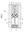
- FIG. 3 is a schematic diagram of a main part of the solid polyelectrolyte fuel cell. Note that, as to the same parts as those in the cases of the first and second embodiments described above, repetitive description of the items described in the first and second embodiments described above will be omitted by using the same reference numerals as those used in the above description of the first and second embodiments.
- a first gas diffusion layer 34 having conductivity and gas diffusivity is attached so as to cover only a surface of the fuel electrode film 12, which is opposite to a contact surface with a solid polyelectrolyte film 11.
- a second gas diffusion layer 35 having conductivity and gas diffusivity is attached so as to cover only a surface of the oxide electrode film 13, which is opposite to a contact surface with the solid polyelectrolyte film 11.
- spacers 39 which are second deterioration inhibitors having electrical insulating properties are provided so as to hold the solid polyelectrolyte film 11 positioned between the electrode films 12 and 13 and sealants 17.
- the same fluorine resins as those in the case of the insulating layers 18 and 19, other resins, silicon materials and the like are cited. However, the material is not limited to those described above.
- the gas diffusion layers 14 and 15 are positioned on the electrode films 12 and 13 and above the solid polyelectrolyte film 11, in other words, the gas diffusion layers 14 and 15 are larger than the electrode films 12 and 13.
- the insulating layers 18 and 19 are provided between the solid polyelectrolyte film 11 and the gas diffusion layers 14 and 15 positioned above the solid polyelectrolyte film 11 and on the peripheral edges of the gas diffusion layers 14 and 15.
- the gas diffusion layers 34 and 35 are not positioned on the solid polyelectrolyte film 11 but exist only on the electrode films 12 and 13, in other words, the gas diffusion layers 34 and 35 having the same size as the electrode films 12 and 13 are adopted.
- the spacers 39 are provided so as to be interposed between the peripheral side of the solid polyelectrolyte film 11 and the peripheral edges of the gas diffusion layers 34 and 35.
- the spacers 39 are interposed between the peripheral side of the solid polyelectrolyte film 11 and the peripheral edges of the gas diffusion layers 34 and 35, supply of electrons from the edges of the gas diffusion layers 34 and 35 is prevented between (on interfaces between) the peripheral side of the solid polyelectrolyte film 11 and the peripheral edges of the gas diffusion layers 34 and 35. Accordingly, the reaction of the formula (2) on the peripheral edges of the gas diffusion layers 34 and 35 is suppressed. Thus, the generation of radicals can be prevented between the peripheral side of the solid polyelectrolyte film 11 and the peripheral edges of the gas diffusion layers 34 and 35.
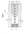
- FIG. 4 is a schematic diagram of a main part of the solid polyelectrolyte fuel cell. Note that, as to the same parts as those in the cases of the first to third embodiments described above, repetitive description of the items described in the first to third embodiments described above will be omitted by using the same reference numerals as those used in the above description of the first to third embodiments.
- a size thereof in a planar direction perpendicular to a lamination direction is larger than that of a first gas diffusion layer 44.
- a size thereof in the planar direction perpendicular to the lamination direction is larger than that of a second gas diffusion layer 45.
- the electrode films 12 and 13 and the gas diffusion layers 34 and 35 have the same size.
- the gas diffusion layers 44 and 45 are smaller than the electrode films 42 and 43. In other words, peripheries of the electrode films 42 and 43 are extended more than those of the gas diffusion layers 44 and 45.
- deterioration of the solid polyelectrolyte film due to the radicals occurs more often in a periphery of the solid polyelectrolyte film (a spot where the solid polyelectrolyte film comes into contact with the gas diffusion layers) than in a center of the solid polyelectrolyte film (a spot where the solid polyelectrolyte film comes into contact with the electrode films).
- the side reaction product such as hydrogen peroxide (H 2 O 2 ) is decomposed into water and oxygen by the catalytic metal in the electrode films between the solid polyelectrolyte film and the electrode films before generation of radicals such as a hydroxy radical ( ⁇ OH) (see the formula (1)).
- the peripheries of the electrode films 42 and 43 are extended more than those of the gas diffusion layers 44 and 45.
- the peripheries of the electrode films 42 and 43 are set to be first deterioration inhibitors.
- the radicals such as a hydroxy radical ( ⁇ OH) from the side reaction product such as hydrogen peroxide (H 2 O 2 )
- the side reaction product such as hydrogen peroxide (H 2 O 2 ) is decomposed into water and oxygen.
- the peripheral side of the solid polyelectrolyte film 11 is relaxed and the peripheral edges of the gas diffusion layers 44 and 45 come into contact with the peripheral side of the solid polyelectrolyte film 11, the peripheral edges of the gas diffusion layers 44 and 45 and the peripheral side of the solid polyelectrolyte film 11 can be prevented from coming into contact with each other since the peripheries of the electrode films 42 and 43 are extended more than those of the gas diffusion layers 44 and 45.
- FIG. 5 is a schematic diagram of a main part of the solid polyelectrolyte fuel cell. Note that, as to the same parts as those in the cases of the first to fourth embodiments described above, repetitive description of the items described in the first to fourth embodiments described above will be omitted by using the same reference numerals as those used in the above description of the first to fourth embodiments.
- spacers 59 which are second deterioration inhibitors having electrical insulating properties are provided so as to be positioned between extended electrode films 42 and 43 and separators 16.
- the spacers 59 As a material of the spacers 59, the same fluorine resins as those in the case of the insulating layers 18 and 19, other resins, silicon materials and the like are cited. However, the material is not limited to those described above.
- the solid polyelectrolyte fuel cell 50 according to this embodiment is one obtained by providing the spacers 59 on the peripheral edges of the gas diffusion layers 44 and 45, as in the case of the third embodiment described above, in the solid polyelectrolyte fuel cell 40 according to the fourth embodiment described above.
- FIG. 6 is a schematic diagram of a main part of the solid polyelectrolyte fuel cell. Note that, as to the same parts as those in the cases of the first to fifth embodiments described above, repetitive description of the items described in the first to fifth embodiments described above will be omitted by using the same reference numerals as those used in the above description of the first to fifth embodiments.
- third insulating layers 69 which are third deterioration inhibitors having electrical insulating properties are provided so as to be adjacent to separators 16.
- the same fluorine resins as those in the case of the insulating layers 18 and 19, other resins, silicon materials and the like are cited. However, the material is not limited to those described above.
- the solid polyelectrolyte fuel cell 60 according to this embodiment is one obtained by providing the third insulating layers 69 adjacent to the separators 16 in the buffer spaces 10a so as to separate between the solid polyelectrolyte film 11 and the separators 16 in the solid polyelectrolyte fuel cell 10 according to the first embodiment described above.
- the third insulating layers 69 are provided on the separators 16 in the buffer spaces 10a so as to separate between the solid polyelectrolyte film 11 and the separators 16.
- supply of electrons from the separators 16 is prevented between the solid polyelectrolyte film 11 and the separators 16.
- the reaction of the formula (2) on the solid polyelectrolyte film 11 is suppressed. Consequently, generation of the radicals can be prevented between the solid polyelectrolyte film 11 and the separators 16.
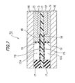
- FIG. 7 is a schematic diagram of a main part of the solid polyelectrolyte fuel cell. Note that, as to the same parts as those in the cases of the first to sixth embodiments described above, repetitive description of the items described in the first to sixth embodiments described above will be omitted by using the same reference numerals as those used in the above description of the first to sixth embodiments.
- third insulating layers 79 which are third deterioration inhibitors having electrical insulating properties are provided so as to be adjacent to a solid polyelectrolyte film 11.
- the third insulating layers 69 are provided adjacent to the separators 16 in the buffer spaces 10a so as to separate between the solid polyelectrolyte film 11 and the separators 16.
- the third insulating layers 79 are provided adjacent to the solid polyelectrolyte film 11 in the buffer spaces 10a so as to separate between the solid polyelectrolyte film 11 and the separators 16.
- the spacers 39 and 59 having electrical insulating properties are used.
- spacers which are second deterioration inhibitors containing catalytic metal, activated carbon or the like for accelerating decomposition of hydrogen peroxide into water and oxygen are used.
- the side reaction product such as hydrogen peroxide (H 2 O 2 ) is decomposed into water and oxygen before generation of radicals such as a hydroxy radical ( ⁇ OH) from the side reaction product such as hydrogen peroxide (H 2 O 2 ) generated between the peripheral side of the solid polyelectrolyte film 11 and the peripheral edges of the gas diffusion layers 34, 35, 44 and 45.
- the reaction of the formula (2) is suppressed between the peripheral side of the solid polyelectrolyte film 11 and the peripheral edges of the gas diffusion layers 34, 35, 44 and 45.
- the radicals such as a hydroxy radical ( ⁇ OH) from the side reaction product such as hydrogen peroxide (H 2 O 2 ) between the peripheral side of the solid polyelectrolyte film 11 and the peripheral edges of the gas diffusion layers 34, 35, 44 and 45.
- the third insulating layers 69 and 79 having electrical insulating properties are used.
- third hydrogen peroxide decomposition layers are used, which are third deterioration inhibitors containing catalytic metal, activated carbon or the like which acclelerates decomposition of hydrogen peroxide into water and oxygen, or at least one kind of oxide, carbonate or phosphate among Ce, T1, Mn, Ag, Yb and W or at least one kind of tungstate and the like among Ce, T1, Mn, Ag and Yb may be used.
- radicals such as a hydroxy radical ( ⁇ OH) from the side reaction product such as hydrogen peroxide (H 2 O 2 ).
- a solid polyelectrolyte fuel cell 80 in which a sealant 87b extended to the separator 16 portion in the buffer space 10a so as to separate between the solid polyelectrolyte film 11 and the separator 16 is adopted as one of the third deterioration inhibitors, for example, instead of one of the third insulating layers 69 and 79, as shown in Fig. 8.
- a sealant 87a having a thickness larger than that of the sealant 87b is adopted as the other third deterioration inhibitor.
- sealants 87a and 87b silicon rubber, fluorine rubber (for example, "Viton (registered trademark)” manufactured by DuPont Dow Elastomer Japan Co. Ltd.) and the like with electrical insulating properties and sealing properties can be used.
- the insulating layers 19, the hydrogen peroxide decomposition layers 29a and 29b or the spacers 39 are provided at the peripheral edges of the gas diffusion layers 14, 15, 34 and 35.
- the insulating layers 18, 19, 69 and 79, the hydrogen peroxide decomposition layers 28a, 28b, 29a and 29b, or the spacers 39 and 59 are provided on the both sides of the fuel electrode films 12 and 42 and the oxide electrode films 13 and 43.
- the gas diffusion layers 34, 35, 44 and 45 which have the same size as the electrode films 12 and 13 or are smaller than the electrode films 42 and 43, are adopted.
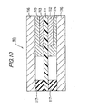
- a solid polyelectrolyte fuel cell 90 in which a peripheral portion 91a of a solid polyelectrolyte film 91 exposed from the electrode films 12 and 13 in the cell contains a deterioration inhibitor (for example, at least one kind of metal ion among Ce, Tl, Mn, Ag, Yb and W) which suppresses generation of radicals by decomposing hydrogen peroxide into water and oxygen.
- a deterioration inhibitor for example, at least one kind of metal ion among Ce, Tl, Mn, Ag, Yb and W
- a solid polyelectrolyte fuel cell according to the present invention can be very effectively utilized in various industries.
Landscapes
- Chemical & Material Sciences (AREA)
- Life Sciences & Earth Sciences (AREA)
- Engineering & Computer Science (AREA)
- Manufacturing & Machinery (AREA)
- Sustainable Development (AREA)
- Sustainable Energy (AREA)
- Chemical Kinetics & Catalysis (AREA)
- Electrochemistry (AREA)
- General Chemical & Material Sciences (AREA)
- Composite Materials (AREA)
- Fuel Cell (AREA)
- Inert Electrodes (AREA)
Applications Claiming Priority (2)
| Application Number | Priority Date | Filing Date | Title |
|---|---|---|---|
| JP2005162469 | 2005-06-02 | ||
| JP2005301234A JP5166690B2 (ja) | 2005-06-02 | 2005-10-17 | 固体高分子電解質形燃料電池 |
Publications (2)
| Publication Number | Publication Date |
|---|---|
| EP1729361A2 true EP1729361A2 (de) | 2006-12-06 |
| EP1729361A3 EP1729361A3 (de) | 2008-01-09 |
Family
ID=36866891
Family Applications (1)
| Application Number | Title | Priority Date | Filing Date |
|---|---|---|---|
| EP06003385A Withdrawn EP1729361A3 (de) | 2005-06-02 | 2006-02-20 | Feststoffpolyelekrotlytbrennstoffzelle |
Country Status (4)
| Country | Link |
|---|---|
| US (1) | US7670708B2 (de) |
| EP (1) | EP1729361A3 (de) |
| JP (1) | JP5166690B2 (de) |
| CA (1) | CA2536731A1 (de) |
Cited By (4)
| Publication number | Priority date | Publication date | Assignee | Title |
|---|---|---|---|---|
| EP2525429A4 (de) * | 2010-01-14 | 2014-01-01 | Honda Motor Co Ltd | Brennstoffzelle |
| WO2014011153A1 (en) | 2012-07-10 | 2014-01-16 | United Technologies Corporation | Fuel cell electrode assembly |
| EP2808929A4 (de) * | 2012-01-27 | 2015-07-08 | Nissan Motor | Brennstoffzelle |
| FR3056337A1 (fr) * | 2016-09-22 | 2018-03-23 | Commissariat A L'energie Atomique Et Aux Energies Alternatives | Reacteur d'electrolyse de l'eau (soec) ou pile a combustible (sofc) a taux d'utilisation de vapeur d'eau ou respectivement de combustible augmente |
Families Citing this family (13)
| Publication number | Priority date | Publication date | Assignee | Title |
|---|---|---|---|---|
| JP2010118284A (ja) * | 2008-11-14 | 2010-05-27 | Mitsubishi Heavy Ind Ltd | 固体高分子形燃料電池発電システム |
| JP2010170892A (ja) * | 2009-01-23 | 2010-08-05 | Panasonic Corp | 燃料電池 |
| JP5365326B2 (ja) * | 2009-04-22 | 2013-12-11 | トヨタ自動車株式会社 | 燃料電池用膜電極接合体の製造方法 |
| KR102353489B1 (ko) | 2011-01-25 | 2022-01-19 | 에베 그룹 에. 탈너 게엠베하 | 웨이퍼들의 영구적 결합을 위한 방법 |
| KR101794390B1 (ko) | 2011-04-08 | 2017-12-01 | 에베 그룹 에. 탈너 게엠베하 | 웨이퍼 영구 접합 방법 |
| EP2709198A1 (de) * | 2011-05-12 | 2014-03-19 | Panasonic Corporation | Polymerelektrolyt-brennstoffzelle und verfahren zur herstellung davon |
| JP5936889B2 (ja) * | 2012-03-09 | 2016-06-22 | 本田技研工業株式会社 | 燃料電池 |
| JP6104096B2 (ja) * | 2012-08-14 | 2017-03-29 | 本田技研工業株式会社 | 燃料電池 |
| JP5987759B2 (ja) * | 2013-04-04 | 2016-09-07 | トヨタ自動車株式会社 | 燃料電池 |
| WO2016016254A1 (de) * | 2014-08-01 | 2016-02-04 | Siemens Aktiengesellschaft | Brennstoffzellenanordnung und verfahren zum betreiben einer brennstoffzellenanordnung |
| DE102017221769A1 (de) | 2017-12-04 | 2019-06-06 | Bayerische Motoren Werke Aktiengesellschaft | Batteriemodul für eine Hochvoltbatterie eines Kraftfahrzeugs, Hochvoltbatterie sowie Kraftfahrzeug |
| JP2021099953A (ja) * | 2019-12-23 | 2021-07-01 | トヨタ自動車株式会社 | 燃料電池単位セル |
| CN113149162A (zh) * | 2021-05-31 | 2021-07-23 | 北京纳米能源与系统研究所 | 羟基自由基产生方法、有机废水处理方法及装置 |
Citations (4)
| Publication number | Priority date | Publication date | Assignee | Title |
|---|---|---|---|---|
| US6335112B1 (en) | 1998-09-30 | 2002-01-01 | Aisin Seiki Kabushiki Kaisha | Solid polymer electrolyte fuel cell |
| JP3271410B2 (ja) | 1993-12-29 | 2002-04-02 | トヨタ自動車株式会社 | 燃料電池とその固体高分子電解質膜および電極 |
| JP3345240B2 (ja) | 1995-11-27 | 2002-11-18 | 三洋電機株式会社 | 固体高分子型燃料電池及びその製造方法 |
| JP2003123777A (ja) | 2001-10-19 | 2003-04-25 | Matsushita Electric Ind Co Ltd | 高分子電解質型燃料電池 |
Family Cites Families (33)
| Publication number | Priority date | Publication date | Assignee | Title |
|---|---|---|---|---|
| AU664703B2 (en) * | 1991-06-04 | 1995-11-30 | Ballard Power Systems Inc. | Gasketed membrane electrode assembly for electrochemical fuel cells |
| JP3271801B2 (ja) | 1992-09-22 | 2002-04-08 | 田中貴金属工業株式会社 | 高分子固体電解質型燃料電池、該燃料電池の加湿方法、及び製造方法 |
| JPH07220742A (ja) * | 1994-01-27 | 1995-08-18 | Matsushita Electric Ind Co Ltd | 固体高分子電解質型燃料電池及び該燃料電池の電極−イオン交換膜接合体の製造方法 |
| JPH0845517A (ja) * | 1994-07-28 | 1996-02-16 | Tanaka Kikinzoku Kogyo Kk | 高分子電解質型燃料電池用シール構造及びその製造方法 |
| US6149810A (en) | 1994-11-23 | 2000-11-21 | Lynntech, Inc. | Membrane with supported internal passages |
| JPH11233128A (ja) * | 1998-02-17 | 1999-08-27 | Honda Motor Co Ltd | 燃料電池 |
| JP2001015133A (ja) * | 1999-07-01 | 2001-01-19 | Mitsubishi Plastics Ind Ltd | 固体高分子型燃料電池 |
| JP3925764B2 (ja) | 1999-10-19 | 2007-06-06 | 株式会社豊田中央研究所 | 高耐久性固体高分子電解質 |
| WO2002037586A1 (en) | 2000-10-31 | 2002-05-10 | Matsushita Electric Industrial Co., Ltd. | High polymer electrolyte fuel cell |
| AU2001260606B2 (en) * | 2000-11-21 | 2006-10-19 | Nok Corporation | Constituent part for fuel cell |
| JP3690682B2 (ja) | 2001-01-31 | 2005-08-31 | 松下電器産業株式会社 | 高分子電解質型燃料電池およびその電解質膜−ガスケット組立体 |
| ATE447775T1 (de) * | 2001-03-07 | 2009-11-15 | Panasonic Corp | Polymer-elektrolyttyp-brennstoffzelle und verfahren zur herstellung |
| US6916575B2 (en) | 2001-03-08 | 2005-07-12 | Matsushita Electric Industrial Co., Ltd. | Polymer electrolyte type fuel cell |
| JP3786185B2 (ja) * | 2001-06-22 | 2006-06-14 | 信越化学工業株式会社 | 固体高分子型燃料電池セパレータシール用ゴム組成物及びこれを用いたシール材並びに固体高分子型燃料電池セパレータ |
| DE10130828A1 (de) | 2001-06-27 | 2003-01-16 | Basf Ag | Brennstoffzelle |
| EP1298751A3 (de) | 2001-09-27 | 2006-04-26 | Matsushita Electric Industrial Co., Ltd. | Polymer-Electrolyt-Brennstoffzelle und ihr Herstellugsverfahren |
| JP3816369B2 (ja) * | 2001-10-22 | 2006-08-30 | 本田技研工業株式会社 | 電解質膜・電極構造体及び燃料電池 |
| JP3952139B2 (ja) * | 2001-11-22 | 2007-08-01 | Nok株式会社 | 燃料電池 |
| KR100933647B1 (ko) * | 2002-01-15 | 2009-12-23 | 스미또모 가가꾸 가부시끼가이샤 | 고분자 전해질 조성물 및 이의 용도 |
| EP1472751A2 (de) | 2002-01-22 | 2004-11-03 | E.I. du Pont de Nemours and Company | Verbundene membranelektrodeneinheit und deren herstellung |
| JP4160328B2 (ja) * | 2002-07-03 | 2008-10-01 | 本田技研工業株式会社 | 燃料電池用セパレータの製造方法 |
| US6991871B2 (en) | 2002-08-27 | 2006-01-31 | Honda Giken Kogyo Kabushiki Kaisha | Fuel cell |
| US6861173B2 (en) * | 2002-10-08 | 2005-03-01 | Sompalli Bhaskar | Catalyst layer edge protection for enhanced MEA durability in PEM fuel cells |
| US7470483B2 (en) | 2002-12-11 | 2008-12-30 | Panasonic Corporation | Electrolyte membrane-electrode assembly for fuel cell and operation method of fuel cell using the same |
| JP4739685B2 (ja) * | 2003-03-14 | 2011-08-03 | パナソニック株式会社 | 高分子電解質型燃料電池 |
| ATE541330T1 (de) | 2003-06-24 | 2012-01-15 | Asahi Glass Co Ltd | Membran-elektrodenbaugruppe für eine festpolymer- brennstoffzelle und herstellungsverfahren dafür |
| JP4326271B2 (ja) * | 2003-06-26 | 2009-09-02 | 株式会社豊田中央研究所 | 遷移金属酸化物含有固体高分子電解質 |
| JP4845077B2 (ja) * | 2003-08-19 | 2011-12-28 | 株式会社豊田中央研究所 | 固体高分子型燃料電池用電解質膜電極接合体および固体高分子型燃料電池 |
| JP4979179B2 (ja) | 2003-08-22 | 2012-07-18 | 株式会社豊田中央研究所 | 固体高分子型燃料電池およびその製造方法 |
| WO2005035247A2 (en) | 2003-08-29 | 2005-04-21 | E.I. Dupont De Nemours And Company | Unitized membrane electrode assembly and process for its preparation |
| JP4582689B2 (ja) * | 2004-03-16 | 2010-11-17 | 株式会社豊田中央研究所 | 固体高分子型燃料電池 |
| EP1842259A4 (de) * | 2004-12-28 | 2008-05-28 | Utc Fuel Cells Llc | Mea-dichtungsstruktur mit katalysierter schicht |
| JP2006294293A (ja) * | 2005-04-06 | 2006-10-26 | Toyota Motor Corp | 燃料電池 |
-
2005
- 2005-10-17 JP JP2005301234A patent/JP5166690B2/ja not_active Expired - Fee Related
-
2006
- 2006-02-16 US US11/355,185 patent/US7670708B2/en not_active Expired - Fee Related
- 2006-02-16 CA CA002536731A patent/CA2536731A1/en not_active Abandoned
- 2006-02-20 EP EP06003385A patent/EP1729361A3/de not_active Withdrawn
Patent Citations (4)
| Publication number | Priority date | Publication date | Assignee | Title |
|---|---|---|---|---|
| JP3271410B2 (ja) | 1993-12-29 | 2002-04-02 | トヨタ自動車株式会社 | 燃料電池とその固体高分子電解質膜および電極 |
| JP3345240B2 (ja) | 1995-11-27 | 2002-11-18 | 三洋電機株式会社 | 固体高分子型燃料電池及びその製造方法 |
| US6335112B1 (en) | 1998-09-30 | 2002-01-01 | Aisin Seiki Kabushiki Kaisha | Solid polymer electrolyte fuel cell |
| JP2003123777A (ja) | 2001-10-19 | 2003-04-25 | Matsushita Electric Ind Co Ltd | 高分子電解質型燃料電池 |
Cited By (8)
| Publication number | Priority date | Publication date | Assignee | Title |
|---|---|---|---|---|
| EP2525429A4 (de) * | 2010-01-14 | 2014-01-01 | Honda Motor Co Ltd | Brennstoffzelle |
| EP2808929A4 (de) * | 2012-01-27 | 2015-07-08 | Nissan Motor | Brennstoffzelle |
| WO2014011153A1 (en) | 2012-07-10 | 2014-01-16 | United Technologies Corporation | Fuel cell electrode assembly |
| EP2873106A4 (de) * | 2012-07-10 | 2016-02-24 | Audi Ag | Brennstoffzellenelektrodenbaugruppe |
| US10205186B2 (en) | 2012-07-10 | 2019-02-12 | Audi Ag | Fuel cell electrode assembly |
| FR3056337A1 (fr) * | 2016-09-22 | 2018-03-23 | Commissariat A L'energie Atomique Et Aux Energies Alternatives | Reacteur d'electrolyse de l'eau (soec) ou pile a combustible (sofc) a taux d'utilisation de vapeur d'eau ou respectivement de combustible augmente |
| WO2018055011A1 (fr) * | 2016-09-22 | 2018-03-29 | Commissariat A L'energie Atomique Et Aux Energies Alternatives | Réacteur d'électrolyse de l'eau (soec) ou pile à combustible (sofc) à taux d'utilisation de vapeur d'eau ou respectivement de combustible augmenté |
| US10991956B2 (en) | 2016-09-22 | 2021-04-27 | Commissariat A L'energie Atomique Et Aux Energies Alternatives | Water electrolysis reactor (SOEC) or fuel cell (SOFC) with an increased rate of water vapour use or fuel use, respectively |
Also Published As
| Publication number | Publication date |
|---|---|
| US7670708B2 (en) | 2010-03-02 |
| JP5166690B2 (ja) | 2013-03-21 |
| CA2536731A1 (en) | 2006-12-02 |
| US20060275650A1 (en) | 2006-12-07 |
| EP1729361A3 (de) | 2008-01-09 |
| JP2007012583A (ja) | 2007-01-18 |
Similar Documents
| Publication | Publication Date | Title |
|---|---|---|
| US7670708B2 (en) | Solid polyelectrolyte fuel cell | |
| US7445866B2 (en) | Fuel cell stack | |
| US8283087B2 (en) | Seal structure adopted in membrane electrode assembly for fuel cell | |
| JP4562501B2 (ja) | 燃料電池 | |
| CN113299964B (zh) | 燃料电池堆 | |
| US20060210859A1 (en) | Pump having noise-proof and vibration-proof structure and fuel cell system using the same | |
| JP2009199741A (ja) | 燃料電池及び加湿器 | |
| JP4813766B2 (ja) | 燃料電池スタック | |
| JP5101824B2 (ja) | 燃料電池 | |
| JP6315845B2 (ja) | 燃料電池スタック | |
| JP6204328B2 (ja) | 燃料電池スタック | |
| CN100418259C (zh) | 固体高分子电解质型燃料电池 | |
| JP4360118B2 (ja) | 燃料電池セル | |
| JP6104103B2 (ja) | 燃料電池 | |
| JP5714462B2 (ja) | 燃料電池 | |
| JP5291613B2 (ja) | 固体高分子形燃料電池 | |
| JP6315844B2 (ja) | 燃料電池スタック | |
| KR20220075691A (ko) | 연료전지 인클로저 | |
| JP5364278B2 (ja) | 燃料電池のシール構造 | |
| JP2008235188A (ja) | 燃料電池セル及び燃料電池積層体 | |
| JP2021099953A (ja) | 燃料電池単位セル | |
| US20070190394A1 (en) | Fuel cell | |
| JP2006048936A (ja) | 燃料電池 | |
| JP5802181B2 (ja) | 燃料電池 | |
| JP2016085820A (ja) | 燃料電池 |
Legal Events
| Date | Code | Title | Description |
|---|---|---|---|
| PUAI | Public reference made under article 153(3) epc to a published international application that has entered the european phase |
Free format text: ORIGINAL CODE: 0009012 |
|
| 17P | Request for examination filed |
Effective date: 20060220 |
|
| AK | Designated contracting states |
Kind code of ref document: A2 Designated state(s): AT BE BG CH CY CZ DE DK EE ES FI FR GB GR HU IE IS IT LI LT LU LV MC NL PL PT RO SE SI SK TR |
|
| AX | Request for extension of the european patent |
Extension state: AL BA HR MK YU |
|
| PUAL | Search report despatched |
Free format text: ORIGINAL CODE: 0009013 |
|
| AK | Designated contracting states |
Kind code of ref document: A3 Designated state(s): AT BE BG CH CY CZ DE DK EE ES FI FR GB GR HU IE IS IT LI LT LU LV MC NL PL PT RO SE SI SK TR |
|
| AX | Request for extension of the european patent |
Extension state: AL BA HR MK YU |
|
| AKX | Designation fees paid |
Designated state(s): DE FR GB IT |
|
| 17Q | First examination report despatched |
Effective date: 20130326 |
|
| GRAJ | Information related to disapproval of communication of intention to grant by the applicant or resumption of examination proceedings by the epo deleted |
Free format text: ORIGINAL CODE: EPIDOSDIGR1 |
|
| GRAP | Despatch of communication of intention to grant a patent |
Free format text: ORIGINAL CODE: EPIDOSNIGR1 |
|
| RIC1 | Information provided on ipc code assigned before grant |
Ipc: H01M 8/04 20060101ALI20140310BHEP Ipc: H01M 8/10 20060101ALI20140310BHEP Ipc: H01M 8/02 20060101AFI20140310BHEP |
|
| INTG | Intention to grant announced |
Effective date: 20140415 |
|
| RIN1 | Information on inventor provided before grant (corrected) |
Inventor name: TOYODA, ICHIRO Inventor name: WATANABE, SATORU Inventor name: YAMADA, AKIHIKO Inventor name: TSURUMAKI, SHIGERU Inventor name: MORIGA, TAKUYA Inventor name: ITO, HIDEKI |
|
| STAA | Information on the status of an ep patent application or granted ep patent |
Free format text: STATUS: THE APPLICATION IS DEEMED TO BE WITHDRAWN |
|
| 18D | Application deemed to be withdrawn |
Effective date: 20140826 |