EP1729376A2 - Verriegelungshebelmechanismus für Verbinder - Google Patents
Verriegelungshebelmechanismus für Verbinder Download PDFInfo
- Publication number
- EP1729376A2 EP1729376A2 EP06290728A EP06290728A EP1729376A2 EP 1729376 A2 EP1729376 A2 EP 1729376A2 EP 06290728 A EP06290728 A EP 06290728A EP 06290728 A EP06290728 A EP 06290728A EP 1729376 A2 EP1729376 A2 EP 1729376A2
- Authority
- EP
- European Patent Office
- Prior art keywords
- locking lever
- locking
- plugging
- cam path
- lever
- Prior art date
- Legal status (The legal status is an assumption and is not a legal conclusion. Google has not performed a legal analysis and makes no representation as to the accuracy of the status listed.)
- Granted
Links
Images


Classifications
-
- H—ELECTRICITY
- H01—ELECTRIC ELEMENTS
- H01R—ELECTRICALLY-CONDUCTIVE CONNECTIONS; STRUCTURAL ASSOCIATIONS OF A PLURALITY OF MUTUALLY-INSULATED ELECTRICAL CONNECTING ELEMENTS; COUPLING DEVICES; CURRENT COLLECTORS
- H01R13/00—Details of coupling devices of the kinds covered by groups H01R12/70 or H01R24/00 - H01R33/00
- H01R13/62—Means for facilitating engagement or disengagement of coupling parts or for holding them in engagement
- H01R13/629—Additional means for facilitating engagement or disengagement of coupling parts, e.g. aligning or guiding means, levers, gas pressure electrical locking indicators, manufacturing tolerances
- H01R13/62933—Comprising exclusively pivoting lever
- H01R13/62938—Pivoting lever comprising own camming means
Definitions
- the present invention relates to a connector locking lever.
- the present invention relates in particular, although not limited to, a locking lever for the rapid connection and disconnection of electronic boxes in an aircraft, the electronic boxes being used for example for video and / or audio applications .
- contact elements of a first plug-in part which is in the form of a cable harness plug, are removably coupled to contact elements opposite one another.
- plugging part which is in the form of a plug contained in an electronic box.
- connection or disconnection operations of such interlocking elements can be difficult to perform when the mechanical stresses during connection are important.
- a poor connection may result in false contacts or even damage to the contact elements.
- the electronic boxes are arranged under the seats of an aircraft. This has the disadvantage that the passenger, sitting on the seat, can act on the electronic box.
- the first and second plugging portions may move relative to each other, which may cause disconnection of the electronic unit. Such a connection therefore poses problems of reliability and security.
- the object of the present invention is to propose a locking lever for a connector which avoids at least some of the aforementioned drawbacks, which allows connection and disconnection. simpler two plugging parts, and that keeps the two plugging parts in the connected position.
- the subject of the invention is a locking lever for a connector, said connector comprising a first plug-in part, fixed, and a second plug-in part capable of being connected to said first plug-in part by a translation in a connection direction, said locking lever having two end portions adapted to be pivotably attached, along an axis substantially perpendicular to said connection direction, on two opposite faces of said first insertion part, characterized in each of said end portions comprises a cam path, said locking lever being pivotable between a release position, in which an open end of each of said cam paths is adapted to be positioned at a stub of said second plugging part, and a locking position in which each of said pins is able to position itself in a locking portion of said cam path, said end portion being resiliently deformable to allow said pin to penetrate said locking portion and exert a compressive force between said first plug portion and said second portion of said cam portion; plugging.
- each of said end portions comprises a groove extending along a portion of said corresponding cam path, one end of said groove opening at an end of said cam path, so as to that said cam path defines with said groove a tongue adapted to be deformed elastically to allow deformation of said portion terminal in response to a pressing force exerted on said tongue of said cam path.
- said tongue is able to elastically assume a stable position once said pin has positioned in said notch to maintain the connection force.
- said second plugging part is connected to an electronic box, said first plugging part being connected to an electronic device integrated in a vehicle, said first plugging part being fixed to said vehicle .
- the locking lever comprises two lateral branches interconnected by a transverse spacer, said lateral branches being able to extend along two opposite faces of said electronic unit when said locking lever is in said locking position.
- said spacer is able to extend substantially parallel to a face of said electronic housing when said locking lever is in said locking position, at least a handle portion of said spacer being offset from said face of said housing.
- said vehicle is an aircraft, said electronic box being disposed under the seat of a seat of said aircraft, so that, when said locking lever is in said locking position, said lever locking is substantially parallel to the plane of said seat, said seat being able to press on said locking lever to maintain said locking lever in said locking position.
- a connector 1 having a first plugging portion 2 and a second plugging portion 3, intended to be assembled to one another by interlocking.
- the first one Part 2 is connected to an electronic device (not shown), for example integrated in a structure of an aircraft, the first part 2 being fixed relative to the structure.
- the second part 3 is connected to an electronic box 4.
- the electronic box is intended to be disposed under the seat of a seat (not shown) of the aircraft.
- the second part 3 can be connected to the first part 2 by a translation in an X connection direction.
- the second part 3 comprises for example, as contact elements (not shown), a multiplicity of plug sockets arranged in line.
- the plug sockets are intended to surround, in the connected position, opposite contact elements (not shown) of the first part 2, for example pins.
- Such a connector is known per se.
- the connector 1 comprises a U-shaped locking lever 5.
- the lever 5 comprises two substantially identical lateral branches 6, connected together by a transverse spacer 8.
- the lateral branches 6 extend parallel to each other.
- the free ends 9 of the branches 6 are pivotally attached to pivot elements 11 arranged on two opposite lateral faces 12 of the first part 2.
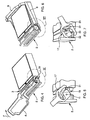
- the locking lever 5 can thus pivot with respect to the first part 2 around a Y axis substantially orthogonal to the X axis, between a rest position ( Figure 1) and a locking position (Figure 8).
- the spacer 8 has a central portion 13 serving as a handle during the manipulation of the lever 5, as will be described in detail below.
- Each branch 6 has, starting from the spacer 8, a rectilinear central portion 16 arranged to form a right angle with the corresponding end portion 15. At the free end 9, each branch 6 has an end portion 17.
- Each end portion 17 is substantially planar and disposed in the same plane as the middle portion 16.
- Each end portion 17 has a groove 18 defining a cam path, the curvature of the cam path 18 being directed so that the cam path 18 is wound around the pivot 11.
- the distance of the cam path 18 to the pivot 11 decreases from its end 19 towards the opposite end 24 of the cam path 18.
- a groove 21 extends along a portion 22 of the cam path 18, one end 23 of the groove 21 opening at the end 24.
- the cam path 18 defines with the groove 21 a tongue 25 adapted to be elastically deformed in response to a pressing force exerted on the tab 25 of the cam path 18, as will be described in detail below.
- the second part 3 comprises, on each of two opposite lateral faces 30 corresponding to the faces 12, a lug 31 adapted to engage in the cam path 18.
- the lugs 31 are arranged so that, when the second portion 3 is in position. abutting against the first part 2, each lug 31 is at one of the openings 20.
- the tongue 25 In the vicinity of the end 24, the tongue 25 has a rounded notch which defines a recess 32 adapted to receive the pin 31 in the locking position of the lever 5.
- each pin 31 slides in the corresponding cam path 18, towards the end 24.
- the second part 3 under the effect of the cam tracks 18 acting on the pins 31, engages in the first part 2.
- the tongue 25 begins to deform by elasticity, due to the pressing force exerted by the lug 31 on the tongue 25.
- the tongue 25 assumes a stable position by elasticity, which causes the creation of a hard point 33 to maintain the lug 31 in the recess 32 and exert a force of compression between parts 2 and 3. This allows in particular to compensate for the tolerance intervals of the coupling. In this position, the contact elements of the first and second parts 2 and 3 are correctly connected.
- the central portion 13 of the spacer 8 extends parallel to the upper face 34 of the housing 4, substantially parallel to the axis Y.
- End portions 15 of the spacer 8 are extend along the opposite side faces 35 of the housing, substantially perpendicular to the axis X.
- the branches 6 extend along the side faces 35, substantially parallel to the axis X.
- the lever 5, when in the locked position, is substantially parallel to the casing 4. This allows the casing 4 to be placed under the seat of a seat of the aircraft substantially parallel to the plane of the seat. sitting, that is to say horizontally.
- the support of the seat on the lever 5 helps maintain the lever 5 in its horizontal position, that is to say in its locking position, which prevents inadvertent disconnection of the housing 4.
- a passenger can not access the housing 4, the latter being disposed under the seat of his seat.
- the cam paths 18 of the lever 5 thus make it possible to ensure good distribution of the forces during the connection and disconnection operations, which facilitates these operations for the user.
- the lever also makes it possible to define the insertion depth and to ensure the guidance along the X axis of the second part 3 with respect to the first part 2, which avoids twisting or breaking contact elements.
Landscapes
- Details Of Connecting Devices For Male And Female Coupling (AREA)
Applications Claiming Priority (1)
| Application Number | Priority Date | Filing Date | Title |
|---|---|---|---|
| FR0505505A FR2886474A1 (fr) | 2005-05-31 | 2005-05-31 | Levier de verrouillage pour connecteur |
Publications (3)
| Publication Number | Publication Date |
|---|---|
| EP1729376A2 true EP1729376A2 (de) | 2006-12-06 |
| EP1729376A3 EP1729376A3 (de) | 2007-10-03 |
| EP1729376B1 EP1729376B1 (de) | 2009-09-23 |
Family
ID=35708645
Family Applications (1)
| Application Number | Title | Priority Date | Filing Date |
|---|---|---|---|
| EP06290728A Expired - Lifetime EP1729376B1 (de) | 2005-05-31 | 2006-05-05 | Verriegelungshebelmechanismus für Verbinder |
Country Status (8)
| Country | Link |
|---|---|
| US (1) | US7335038B2 (de) |
| EP (1) | EP1729376B1 (de) |
| JP (1) | JP2006339154A (de) |
| CA (1) | CA2548636C (de) |
| DE (1) | DE602006009337D1 (de) |
| ES (1) | ES2333899T3 (de) |
| FR (1) | FR2886474A1 (de) |
| MX (1) | MXPA06005971A (de) |
Cited By (5)
| Publication number | Priority date | Publication date | Assignee | Title |
|---|---|---|---|---|
| WO2008138613A1 (de) * | 2007-05-15 | 2008-11-20 | Phoenix Contact Gmbh & Co. Kg | Verriegelungsbügel für steckverbindergehäuse |
| EP2133959A3 (de) * | 2008-06-13 | 2013-12-18 | Harting Electric GmbH & Co. KG | Verriegelungsvorrichtung für Steckverbindergehäuse |
| EP3012922A1 (de) * | 2014-10-20 | 2016-04-27 | Multi-Holding AG | Schwenkhebelanordnung für Gehäuseanordnung |
| EP2451021B1 (de) * | 2010-11-05 | 2018-08-01 | Lapp Engineering & Co. | Verriegelungseinrichtung und Gehäuse für einen Steckverbinder mit dieser Verriegelungseinrichtung |
| CN108695646A (zh) * | 2017-04-04 | 2018-10-23 | 泰连德国有限公司 | 插头连接器和产生插头连接的方法 |
Families Citing this family (15)
| Publication number | Priority date | Publication date | Assignee | Title |
|---|---|---|---|---|
| DE102004033911B3 (de) * | 2004-07-14 | 2005-12-01 | Bernd Lenz | Vorrichtung zur Aufnahme eines tragbaren Computers (Notebooks, Laptops) |
| JP5102519B2 (ja) | 2007-03-15 | 2012-12-19 | Dowaメタルマイン株式会社 | 砒素含有固形物およびその製法 |
| US7344394B1 (en) * | 2007-10-16 | 2008-03-18 | International Business Machines Corporation | Multiple location latch mechanism with single actuation |
| EP2180558A1 (de) | 2008-10-23 | 2010-04-28 | Tyco Electronics AMP GmbH | Verbinder mit Selbsthaltefeststellvorrichtung |
| JP5419224B2 (ja) | 2010-04-13 | 2014-02-19 | 日立金属株式会社 | レバー式コネクタ |
| JP4947181B2 (ja) * | 2010-04-13 | 2012-06-06 | 日立電線株式会社 | レバー式コネクタ |
| JP5666180B2 (ja) | 2010-07-06 | 2015-02-12 | 矢崎総業株式会社 | レバー式コネクタ |
| EP2559596B1 (de) * | 2011-08-17 | 2015-10-07 | Harman Becker Automotive Systems GmbH | Rahmen mit Schnellverbindung für ein Fahrzeug |
| US20170005444A1 (en) * | 2014-04-11 | 2017-01-05 | HARTING Electronics GmbH | Plug-in connector |
| DE102016120929B4 (de) * | 2016-11-03 | 2018-10-31 | Harting Electric Gmbh & Co. Kg | Verriegelungsbügel für ein Steckverbindergehäuse |
| US10490938B2 (en) * | 2017-10-20 | 2019-11-26 | Lear Corporation | Electrical connector with assist lever |
| US10270207B1 (en) * | 2017-10-20 | 2019-04-23 | Lear Corporation | Electrical connector with assist lever |
| US10601177B1 (en) * | 2018-09-07 | 2020-03-24 | Lear Corporation | Electrical connector lock with reverse stop |
| USD937068S1 (en) * | 2019-07-08 | 2021-11-30 | Harting Electric Gmbh & Co. Kg | Locking device |
| JP7025464B2 (ja) * | 2020-02-28 | 2022-02-24 | 矢崎総業株式会社 | コネクタ |
Family Cites Families (5)
| Publication number | Priority date | Publication date | Assignee | Title |
|---|---|---|---|---|
| JP2595402B2 (ja) * | 1992-03-17 | 1997-04-02 | 矢崎総業株式会社 | コネクタの結合装置 |
| US5474462A (en) * | 1992-05-01 | 1995-12-12 | Yazaki Corporation | Connector system with a lever requiring small force |
| JP3002940B2 (ja) * | 1994-02-18 | 2000-01-24 | 矢崎総業株式会社 | レバー式コネクタ |
| DE10223928A1 (de) * | 2001-05-29 | 2003-01-23 | Sumitomo Wiring Systems | Hebeltyp-Verbinder und Verfahren zum Zusammenbauen |
| JP2006324227A (ja) * | 2005-04-18 | 2006-11-30 | Yazaki Corp | コネクタ |
-
2005
- 2005-05-31 FR FR0505505A patent/FR2886474A1/fr not_active Withdrawn
-
2006
- 2006-05-05 ES ES06290728T patent/ES2333899T3/es not_active Expired - Lifetime
- 2006-05-05 EP EP06290728A patent/EP1729376B1/de not_active Expired - Lifetime
- 2006-05-05 DE DE602006009337T patent/DE602006009337D1/de not_active Expired - Lifetime
- 2006-05-25 MX MXPA06005971A patent/MXPA06005971A/es active IP Right Grant
- 2006-05-26 CA CA2548636A patent/CA2548636C/fr active Active
- 2006-05-30 US US11/442,289 patent/US7335038B2/en active Active
- 2006-05-31 JP JP2006150906A patent/JP2006339154A/ja active Pending
Cited By (6)
| Publication number | Priority date | Publication date | Assignee | Title |
|---|---|---|---|---|
| WO2008138613A1 (de) * | 2007-05-15 | 2008-11-20 | Phoenix Contact Gmbh & Co. Kg | Verriegelungsbügel für steckverbindergehäuse |
| EP2133959A3 (de) * | 2008-06-13 | 2013-12-18 | Harting Electric GmbH & Co. KG | Verriegelungsvorrichtung für Steckverbindergehäuse |
| EP2451021B1 (de) * | 2010-11-05 | 2018-08-01 | Lapp Engineering & Co. | Verriegelungseinrichtung und Gehäuse für einen Steckverbinder mit dieser Verriegelungseinrichtung |
| EP3012922A1 (de) * | 2014-10-20 | 2016-04-27 | Multi-Holding AG | Schwenkhebelanordnung für Gehäuseanordnung |
| CN105522527A (zh) * | 2014-10-20 | 2016-04-27 | 马尔遆公开股份有限公司 | 用于外壳装置的转动杠杆装置 |
| CN108695646A (zh) * | 2017-04-04 | 2018-10-23 | 泰连德国有限公司 | 插头连接器和产生插头连接的方法 |
Also Published As
| Publication number | Publication date |
|---|---|
| EP1729376B1 (de) | 2009-09-23 |
| US20060270257A1 (en) | 2006-11-30 |
| FR2886474A1 (fr) | 2006-12-01 |
| CA2548636C (fr) | 2014-07-15 |
| CA2548636A1 (fr) | 2006-11-30 |
| DE602006009337D1 (de) | 2009-11-05 |
| JP2006339154A (ja) | 2006-12-14 |
| ES2333899T3 (es) | 2010-03-02 |
| MXPA06005971A (es) | 2007-01-26 |
| US7335038B2 (en) | 2008-02-26 |
| EP1729376A3 (de) | 2007-10-03 |
Similar Documents
| Publication | Publication Date | Title |
|---|---|---|
| EP1729376B1 (de) | Verriegelungshebelmechanismus für Verbinder | |
| EP0633633B1 (de) | Kartenverbinder, insbesondere für elektronische Karte | |
| CA2120870C (fr) | Connecteur electrique et plus particulierement connecteur de charge | |
| CA2334997C (fr) | Dispositif d'insertion, d'extraction et de verrouillage d'un module dans une baie | |
| EP0837526B1 (de) | Automatische Anschlussklemme und ein elektrisches Gerät ausgerüstet mit einer solchen Klemme | |
| FR3017252A1 (fr) | Connecteur et ensemble connecteur correspondant | |
| EP3062401B1 (de) | Verbindungssystem für anschluss | |
| EP1424756A1 (de) | Elektrische Verbindungsanordnung eines electrischen Apparates mit einem modularen Verbindungskamm oder ähnlich | |
| EP0677892B1 (de) | Kontakttragender Modul und diesen umfassender Verbinder | |
| FR2790145A1 (fr) | Etrier de verrouillage pour connecteur a fiches | |
| FR2750803A1 (fr) | Dispositif de connexion pour conducteurs electriques | |
| FR2782577A1 (fr) | Connecteur avec fiche et embase a faible force d'insertion, notamment du type a contacts broche/lyre | |
| CA2632270C (fr) | Connecteur electrique | |
| FR3135835A1 (fr) | Appareil électrique à borne de connexion automatique actionnée par l’insertion du conducteur électrique | |
| EP0884806B1 (de) | Elektrischer Steckverbinder mit verbessertem Sicherheitskontakt | |
| FR2505099A1 (fr) | Cosse femelle de contact electrique | |
| EP2257145B1 (de) | Verbindungsvorrichtung | |
| FR3137800A1 (fr) | Prise électrique equipée d’un système d’extraction de prise | |
| FR2705837A3 (fr) | Porte-connecteur à levier perfectionné. | |
| FR2810461A1 (fr) | Socle de prise de courant a trois elements de contact, pourvu d'un obturateur de securite et systeme de raccordement electrique le comprenant | |
| FR2930853A1 (fr) | Connecteur electrique auto-largable | |
| EP0773566A1 (de) | Elektrisches Gerät mit auf einen Kontaktträger montierte beweglicher Kontakte | |
| EP0674357A1 (de) | Verbesserungen an Gehäuseteilen von elektrischen Verbindern | |
| WO2024213590A1 (fr) | Dispositif de maintien d'un appareil de controle medical et installation comprenant un tel dispositif | |
| FR3138250A3 (fr) | Prise électrique equipée d’un système d’extraction de prise |
Legal Events
| Date | Code | Title | Description |
|---|---|---|---|
| PUAI | Public reference made under article 153(3) epc to a published international application that has entered the european phase |
Free format text: ORIGINAL CODE: 0009012 |
|
| AK | Designated contracting states |
Kind code of ref document: A2 Designated state(s): AT BE BG CH CY CZ DE DK EE ES FI FR GB GR HU IE IS IT LI LT LU LV MC NL PL PT RO SE SI SK TR |
|
| AX | Request for extension of the european patent |
Extension state: AL BA HR MK YU |
|
| 17P | Request for examination filed |
Effective date: 20070601 |
|
| PUAL | Search report despatched |
Free format text: ORIGINAL CODE: 0009013 |
|
| AK | Designated contracting states |
Kind code of ref document: A3 Designated state(s): AT BE BG CH CY CZ DE DK EE ES FI FR GB GR HU IE IS IT LI LT LU LV MC NL PL PT RO SE SI SK TR |
|
| AX | Request for extension of the european patent |
Extension state: AL BA HR MK YU |
|
| AKX | Designation fees paid |
Designated state(s): DE ES FR GB IT |
|
| GRAP | Despatch of communication of intention to grant a patent |
Free format text: ORIGINAL CODE: EPIDOSNIGR1 |
|
| GRAS | Grant fee paid |
Free format text: ORIGINAL CODE: EPIDOSNIGR3 |
|
| GRAA | (expected) grant |
Free format text: ORIGINAL CODE: 0009210 |
|
| AK | Designated contracting states |
Kind code of ref document: B1 Designated state(s): DE ES FR GB IT |
|
| REG | Reference to a national code |
Ref country code: GB Ref legal event code: FG4D Free format text: NOT ENGLISH |
|
| REF | Corresponds to: |
Ref document number: 602006009337 Country of ref document: DE Date of ref document: 20091105 Kind code of ref document: P |
|
| REG | Reference to a national code |
Ref country code: ES Ref legal event code: FG2A Ref document number: 2333899 Country of ref document: ES Kind code of ref document: T3 |
|
| PLBE | No opposition filed within time limit |
Free format text: ORIGINAL CODE: 0009261 |
|
| STAA | Information on the status of an ep patent application or granted ep patent |
Free format text: STATUS: NO OPPOSITION FILED WITHIN TIME LIMIT |
|
| 26N | No opposition filed |
Effective date: 20100624 |
|
| REG | Reference to a national code |
Ref country code: FR Ref legal event code: PLFP Year of fee payment: 11 |
|
| REG | Reference to a national code |
Ref country code: FR Ref legal event code: PLFP Year of fee payment: 12 |
|
| REG | Reference to a national code |
Ref country code: FR Ref legal event code: PLFP Year of fee payment: 13 |
|
| REG | Reference to a national code |
Ref country code: DE Ref legal event code: R082 Ref document number: 602006009337 Country of ref document: DE Representative=s name: GLAWE DELFS MOLL PARTNERSCHAFT MBB VON PATENT-, DE Ref country code: DE Ref legal event code: R082 Ref document number: 602006009337 Country of ref document: DE Representative=s name: GLAWE DELFS MOLL PARTGMBB, DE |
|
| PGFP | Annual fee paid to national office [announced via postgrant information from national office to epo] |
Ref country code: FR Payment date: 20250310 Year of fee payment: 20 |
|
| PGFP | Annual fee paid to national office [announced via postgrant information from national office to epo] |
Ref country code: GB Payment date: 20250313 Year of fee payment: 20 |
|
| PGFP | Annual fee paid to national office [announced via postgrant information from national office to epo] |
Ref country code: DE Payment date: 20250311 Year of fee payment: 20 |
|
| PGFP | Annual fee paid to national office [announced via postgrant information from national office to epo] |
Ref country code: ES Payment date: 20250605 Year of fee payment: 20 |
|
| PGFP | Annual fee paid to national office [announced via postgrant information from national office to epo] |
Ref country code: IT Payment date: 20250422 Year of fee payment: 20 |