EP1729430A2 - Drahtlose Sendevorrichtung zur Paketübertragung und Verfahren zur Benutzung von mehreren Antennen - Google Patents
Drahtlose Sendevorrichtung zur Paketübertragung und Verfahren zur Benutzung von mehreren Antennen Download PDFInfo
- Publication number
- EP1729430A2 EP1729430A2 EP06251418A EP06251418A EP1729430A2 EP 1729430 A2 EP1729430 A2 EP 1729430A2 EP 06251418 A EP06251418 A EP 06251418A EP 06251418 A EP06251418 A EP 06251418A EP 1729430 A2 EP1729430 A2 EP 1729430A2
- Authority
- EP
- European Patent Office
- Prior art keywords
- agc
- signal
- wireless
- preamble sequence
- antennas
- Prior art date
- Legal status (The legal status is an assumption and is not a legal conclusion. Google has not performed a legal analysis and makes no representation as to the accuracy of the status listed.)
- Withdrawn
Links
Images


Classifications
-
- H—ELECTRICITY
- H04—ELECTRIC COMMUNICATION TECHNIQUE
- H04B—TRANSMISSION
- H04B7/00—Radio transmission systems, i.e. using radiation field
- H04B7/02—Diversity systems; Multi-antenna system, i.e. transmission or reception using multiple antennas
- H04B7/04—Diversity systems; Multi-antenna system, i.e. transmission or reception using multiple antennas using two or more spaced independent antennas
- H04B7/06—Diversity systems; Multi-antenna system, i.e. transmission or reception using multiple antennas using two or more spaced independent antennas at the transmitting station
- H04B7/0613—Diversity systems; Multi-antenna system, i.e. transmission or reception using multiple antennas using two or more spaced independent antennas at the transmitting station using simultaneous transmission
- H04B7/0667—Diversity systems; Multi-antenna system, i.e. transmission or reception using multiple antennas using two or more spaced independent antennas at the transmitting station using simultaneous transmission of delayed versions of same signal
- H04B7/0671—Diversity systems; Multi-antenna system, i.e. transmission or reception using multiple antennas using two or more spaced independent antennas at the transmitting station using simultaneous transmission of delayed versions of same signal using different delays between antennas
-
- H—ELECTRICITY
- H04—ELECTRIC COMMUNICATION TECHNIQUE
- H04B—TRANSMISSION
- H04B7/00—Radio transmission systems, i.e. using radiation field
- H04B7/02—Diversity systems; Multi-antenna system, i.e. transmission or reception using multiple antennas
- H04B7/04—Diversity systems; Multi-antenna system, i.e. transmission or reception using multiple antennas using two or more spaced independent antennas
Definitions
- the present invention relates to a wireless transmitting device and method for respectively transmitting radio signals in mobile communication system like a wireless LAN, using a wireless packet including a preamble and data.
- IEEE 802.11n The Institute of Electrical and Electronics Engineers (IEEE) is now defining a wireless LAN standard called IEEE 802.11n, which aims to achieve a high throughput of 100 Mbps or more. It is very possible that IEEE 802.11n will employ a technique, called multi-input multi-output (MIMO), for using a plurality of antennas in a transmitter and receiver.
- MIMO multi-input multi-output
- IEEE 802.11n is required to coexist with the standard IEEE 802.11a where OFDM (Orthogonal Frequency Division Multiplex) is used. So, it is required that IEEE 802.11n wireless transmitting device and receiving device have so called backwards compatibility.
- OFDM Orthogonal Frequency Division Multiplex
- a short-preamble sequence used for time synchronization, frequency synchronization and automatic gain control (AGC), a long-preamble sequence used to estimate a channel impulse response, a signal field indicating a modulation scheme used in the wireless packet, and another signal field for IEEE 802.11n are firstly transmitted from a single particular transmit antenna. Subsequently, long-preamble sequences are transmitted from the other three transmit antennas. After finishing the transmission of the preamble, transmission data is transmitted from all the antennas.
- APC automatic gain control
- the proposed preamble is identical to the preamble stipulated in IEEE 802.11a where single transmit antenna is assumed. Therefore, when wireless receiving devices that conform to IEEE 802.11a receive a wireless packet containing the Boer's proposed preamble, they recognize that the packet is based on IEEE 802.11a. Thus, the proposed preamble conforming to both IEEE 802.11a and IEEE 802.11n enables IEEE 802.11a and IEEE 802.11n to coexist.
- A/D converter In wireless receiving devices, demodulation of a received signal is performed by digital signal processing. Therefore, an analog-to-digital (A/D) converter is provided in the devices for digitizing a received analog signal.
- A/D converters have an input dynamic range (an allowable level range of analog signals to be converted). Accordingly, it is necessary to perform automatic gain control (AGC) for adjusting the levels of received signals within the input dynamic range of the A/D converter.
- AGC automatic gain control
- AGC Since the estimation of a channel impulse response using the above-mentioned long preamble sequences is performed by digital signal processing, AGC must be performed using the signal transmitted before the long-preamble sequence.
- AGC is performed using a short-preamble sequence transmitted before the long-preamble sequence from a particular transmit antenna. That is, the receiving level of the short-preamble sequence is measured, and AGC is performed so that the receiving level falls within the input dynamic range of the A/D converter.
- AGC using the short-preamble sequence, the long-preamble sequence and data transmitted from the particular transmit antenna can be received correctly. If all the antennas are arranged apart, the receiving levels of signals transmitted from the antennas are inevitably different from each other.
- a wireless receiving device when a wireless receiving device receives long-preamble sequences transmitted from the other three transmit antennas, or data transmitted from all the antennas, their receiving levels may be much higher or lower than the level acquired by AGC using the short-preamble sequence transmitted from the particular transmit antenna.
- the receiving level exceeds the upper limit of the input dynamic range of the A/D converter, the output of the A/D converter is saturated.
- the receiving level is lower than the lower limit of the input dynamic range of the A/D converter, the output of the A/D converter suffers a severe quantization error. In either case, the A/D converter cannot perform appropriate conversion, which adversely influences the processing after A/D conversion.
- AGC is performed at the receive side using only the short-preamble sequence transmitted from a single transmit antenna, which makes it difficult to deal with variations in receiving level that may occur when signals transmitted from the other antennas in MIMO mode are received.
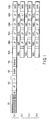
- FIG. 1 shows a format for a wireless packet employed in a first embodiment of the invention.
- This format is a physical layer protocol data unit format for the MIMO (Multiple-Input Multiple-Output) mode and provides interoperability and coexistence with IEEE802.11a wireless stations.
- MIMO Multiple-Input Multiple-Output
- a preamble includes a physical layer convergence protocol (PLCP) signal transmitted from an antenna Tx1.
- the PLCP signal includes a short-preamble sequence 101, first long-preamble sequence 102, first signal field (SIGNAL) 103 and second signal field (SIGNAL 2) 104.
- the short-preamble sequence 101 contains several unit preambles SP.
- the long-preamble sequence 102 contains the unit preambles LP having respective predetermined lengths.
- the preambles LP are longer than the preambles SP.
- the short-preamble sequence 101, first long-preamble sequence 102 and first signal field 103 conform to IEEE 802.11a, while the second signal field 104 is necessary for the new wireless LAN standard IEEE 802.11n.
- First signal field 103 conforming to IEEE 802.11a may be called “legacy signal field”. Since the second signal field 104 is provided for new high throughput wireless LAN standard, it may be called “high throughput signal field”.
- a guard interval GI is inserted between the short-preamble sequence 101 and the long-preamble sequence 102.
- AGC preambles 105A to 105D that are transmitted in parallel from a plurality of antennas Tx1 to Tx4 are positioned.
- the AGC preambles 105A to 105D are transmitted simultaneously from a plurality of antennas Tx1 to Tx4.
- the AGC preambles are MIMO signal since they are transmitted by a plurality of antennas Tx1 to Tx4 and received by a plurality of reception antennas.
- the AGC preambles 105A to 105D are used to enable the receiving device to perform fine AGC when performing MIMO communication. These preambles are unique to perform fine tune the AGC for reception of MIMO mode in accordance with IEEE 802.11n.
- the AGC preambles 105A to 105D may be called “high throughput short trainings field”.
- the short-preamble sequence 101 conforms to IEEE 802.11a, being used for coarse AGC operation, it may be called “legacy short training field”.
- second long-preamble sequences 106A to 109A, 106B to 109B, 106C to 109C and 106D to 109D are positioned.
- the same signal sequences are used as the AGC preambles 105A to 105D.
- different signal sequences may be used as the AGC preambles 105A to 105D.
- a guard interval GI is inserted between each pair of adjacent ones of the unit preambles LP that form the second long-preamble sequences 106A to 109A, 106B to 109B, 106C to 109C and 106D to 109D.
- the second long-preamble sequences 106A to 109A, 106B to 109B, 106C to 109C and 106D to 109D are in an orthogonal relationship.
- the number of unit preambles LP 106-109 for each transmit antenna is equal to the number of transmit antennas in MIMO mode.
- first long-preamble sequence 102 conforming to IEEE 802.11a may be called "legacy long training field”. Since the second long preambles sequences 106-109 are provided for new high throughput wireless LAN standard, it may be called "high throughput long training field".
- the second long-preamble sequences 106A to 109A, 106B to 109B, 106C to 109C and 106D to 109D are transmitted simultaneously from a plurality of antennas Tx1 to Tx4 respectively.
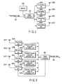
- digital modulator 203 forms a signal for wireless packet by combining transmission data 201 and the above-described preamble outputted from a memory 202.
- the thus-obtained signal for wireless packet is sent to transmitting units 204A to 204D, where they are subjected to processing needed for transmission, for example, digital-to-analog (D/A) conversion, frequency conversion into a radio frequency (RF) band (up-conversion) and power amplification.
- D/A digital-to-analog
- RF radio frequency
- each transmit antenna 205A to 205D the wireless receiving device shown in FIG. 3.
- the antennas Tx1 to Tx4 shown in FIG. 1 are referred to as the antennas 205A to 205D, respectively.
- the AGC preambles 105A to 105D, second long-preamble sequences 106A to 109A, 106B to 109B, 106C to 109C and 106D to 109D, which are positioned after the PLCP signal as shown in FIG. 1, and the data 110A to 110D are transmitted across all the transmit antennas 205A to 205D.
- a plurality of receiving antennas 301A to 301D receive RF signals transmitted from the wireless transmitting device shown in FIG. 2.
- the wireless receiving device may have one receiving antenna or multiple receiving antennas.
- the RF signals received by the receiving antennas 301A to 301D are sent to receiving units 302A to 302D, respectively.
- the receiving units 302A to 302D each perform various types of receiving processing, such as frequency conversion (down-conversion) from the RF band to BB (baseband), automatic gain control (AGC), analog-to-digital conversion, etc., thereby generating a baseband signal.
- the baseband signals from the receiving units 302A to 302D are sent to channel impulse response estimation units 303A to 303D and digital demodulator 304. These units 303A to 303D estimate the impulse responses of the respective propagation paths between the wireless transmitting device of FIG. 2 and the wireless receiving device of FIG. 3. The channel impulse response estimation units 303A to 303D will be described later in detail.
- the digital demodulator 304 demodulates the baseband signals based on the estimated channel impulse response provided by units 303A to 303D, thereby generating received data 305 corresponding to the transmission data 201 shown in FIG. 2.
- the digital demodulator 304 has an equalizer of the channel impulse response at its input section.
- the equalizer performs equalization for correcting the received signal distorted in the propagation path, based on the estimated channel impulse response.
- the digital demodulator 304 also demodulates the equalized signal at appropriate timing determined by the time synchronization, thereby reproducing data.
- FIG. 4 shows the configuration of the receiving unit 302A in detail. Since the other receiving units 302B to 302D have the same configuretion as the unit 302A, only the receiving unit 302A will be described.
- the RF received signal received by the receiving antenna 301A is down-converted by a down-converter 401 into a baseband signal. At this time, The RF signal may be directly converted into a baseband signal, or may be firstly converted into an intermediate frequency (IF) signal and then into a baseband signal.
- IF intermediate frequency
- the baseband signal generated by the down-converter 401 is sent to a variable gain amplifier 402, where it is subjected to perform AGC, i.e., signal level adjustment.
- the signal output from the variable gain amplifier 402 is sampled and quantized by an A/D converter 403.
- the digital signal output from the A/D converter 403 is sent to the outside of the receiving unit 302 and to a gain controller 404.
- the gain controller 404 performs gain calculation based on the digital signal output from the A/D converter 403, and controls the gain of the variable gain amplifier 402. The specific procedure for the gain control will be described later.
- the operation of the wireless receiving device shown in FIGS. 3 and 4 executed for receiving the wireless packet including the preamble whose format is shown in FIG. 1 is as follows. Firstly, the wireless receiving device receives a short-preamble sequence 101 transmitted from the transmit antenna 205A of FIG. 2, and then performs packet edge detection, time synchronization, auto frequency control (AFC) and AGC, using a baseband signal corresponding to the short-preamble sequence 101. AFC is also called frequency synchronization. Packet edge detection, time synchronization and AFC can be performed using known techniques, therefore no description will be given thereof. Only AGC will be explained below.
- AFC auto frequency control
- the baseband signal corresponding to the short-preamble sequence 101 is amplified by the variable gain amplifier 402 in accordance with a predetermined initial gain value.
- the signal output from the variable gain amplifier 402 is input to the gain controller 404 via the A/D converter 403.
- the gain controller 404 calculates a gain from the level of the received signal corresponding to the short-preamble sequence 101, which is acquired after A/D conversion, and controls the gain of the variable gain amplifier 402 in accordance with the calculated gain.
- the level of the baseband signal corresponding to the short-preamble sequence 101 is X. If level X is high, the baseband signal input to the A/D converter 403 exceeds the upper limit of the input dynamic range of the A/D converter 403. As a result, the signal (digital signal) output from the A/D converter 403 is saturated and degraded the quality of signal reception. On the other hand, if level X is extremely low, the signal output from the A/D converter 402 (i.e., the digital signal acquired by A/D conversion) suffers a severe quantization error. Thus, when level X is very high or low, the A/D converter 403 cannot perform appropriate conversion, thereby significantly degrading the quality of signal reception.
- the gain controller 404 controls the gain of the variable gain amplifier 402 so that the level X of the baseband signal corresponding to the short-preamble sequence 101, is adjusted to a target value Z. If the input baseband signal has such a very high level as makes the output of the A/D converter 403 limited to its upper limit level, or if it has a very low level, the gain of the variable gain amplifier 402 may not appropriately be controlled by one control process. In this case, gain control is performed repeatedly. As a result, the level of the baseband signal input to the A/D converter 403 can be adjusted to a value that falls within the input dynamic range of the A/D converter 403. Thus, the gain of the variable gain amplifier 402 is appropriately controlled using the baseband signal corresponding to the short-preamble sequence 101, thereby performing appropriate A/D conversion to avoid a reduction in the quality of signal reception.
- the reception level needed for calculating the gain of the variable gain amplifier 402 is measured using a digital signal output from the A/D converter 403.
- level measurement can be executed using an analog signal acquired before A/D conversion.
- the reception level may be measured in the IF band or RF band, instead of BB.
- the wireless receiving device receives a first long-preamble sequence 102 transmitted from the transmit antenna 205A, and performs the estimation of channel impulse response, i.e., estimates the response (frequency transfer function) of the propagation path between the wireless transmitting device to the wireless receiving device, using a baseband signal corresponding to the long-preamble sequence 102. Since the signal transmitted from the transmit antenna 205A has already been subjected to AGC as described above, the level of an input to the A/D converter 403 is appropriately adjusted when the estimation of channel impulse response is performed. Accordingly, concerning the signal transmitted from the transmit antenna 205A, a highly accurate digital signal is acquired from the A/D converter 403. The estimation of channel impulse can be performed accurately with the acquired digital signal.
- the wireless receiving device receives a first signal field 103 transmitted from the transmit antenna 205A, and demodulates a baseband signal corresponding to the first signal field 103, using the digital demodulator 304 and the above-mentioned propagation path estimation result.
- the first signal field 103 contains information indicating the modulation scheme and wireless packet length of data to be sent after the preamble.
- the first signal field 103 is a field that conveys a kind of attribute information regarding the wireless packet.
- the wireless receiving device continues demodulation using the digital demodulator 304 during the duration of a wireless packet recognized from the wireless packet length information contained in the first signal field 103.
- IEEE 802.11a station Since the packet format from the short-preamble sequence 101 to the first signal field 103 provides interoperability with IEEE 802.11a stations, IEEE 802.11a station is able to perform normal receiving operation without destroying the wireless packet. In other words, another IEEE 802.11a wireless transmitting and receiving device conforming to the IEEE 802.11a standard (a legacy station), upon receiving the first signal field 103, is prohibited to transmit a signal until the wireless packet ends so as not to destroy the wireless packet.
- the wireless receiving device receives a second signal field 104 transmitted from the transmit antenna 205A.
- the second signal field 104 contains identification information indicating a wireless packet that corresponds to a standard other than IEEE 802.11a, e.g., IEEE 802.11n.
- the second signal field 104 indicates that subsequent AGC preambles 105A to 105D, second long-preamble sequences 106A to 109A, 106B to 109B, 106C to 109C and 106D to 109D are signals corresponding to, for example, IEEE 802.11n.
- the wireless receiving device receives AGC preambles 105A to 105D transmitted from the transmit antennas 205A to 205D in parallel.
- the AGC preambles 105A to 105D are transmitted from the transmit antenna 205A that has transmitted the short-preamble sequence 101, first long-preamble sequence 102, first signal field 103 and second signal field 104, and from the transmit antennas 205B to 205D that have transmitted no signal so far.
- the AGC preambles 105A to 105D are received with different receiving levels from the level of the reception signal coming from the transmit antenna 205A.
- the reception level is changed after the MIMO transmission using the multiple transmit antenna.
- the wireless receiving device receives the second signal field 104 and demodulates it using the digital demodulator 304, thereby recognizing that the present wireless packet corresponds to IEEE 802.11n.
- the digital demodulator 304 issues an instruction to restart AGC for fine tune to the receiving units 302A to 302D, thereby re-executing AGC on the AGC preambles 105A to 105D.
- the signals transmitted from the transmit antennas 205A to 205D via the MIMO channel and received at the receiving units 302A to 302D are input to the A/D converter 403 with an appropriately adjusted receiving level.
- the time at which the digital demodulator 304 issues the instruction to start AGC using the AGC preambles 105A to 105D is not limited to the time at which the decoding result of the second signal field 104 is acquired.
- the digital demodulator 304 may confirm, using, for example, a matched filter, the reception of the AGC preambles 105A to 105D, and then supply the receiving units 302A to 302D with an instruction to start AGC.
- AGC is performed only using a short-preamble sequence (legacy short preamble), transmitted from a single transmit antenna.
- AGC is performed using a reception level with which the signal transmitted from the antenna where the short-preamble sequence transmits.
- the device executes gain control by using the acquired gain.
- FIG. 5 is a graph illustrating the distribution of the receiving power of a short preamble and data, acquired when Jan Boer's proposed preamble is utilized.
- the channel is in a multipath environment with a delay spread of 50 nsec (the duration for one data symbol is 4 ⁇ sec).
- the ratio of the receiving level of short preamble (legacy short preamble) to the receiving level of the data varies significantly.
- the short preamble is received with a high receiving level, although the receiving level of data is low. Accordingly, if AGC is adjusted in accordance with the receiving power of the short preamble, the receiving power of the data is lower than the receiving power of the short preamble, resulting in a quantization error in the A/D converter 403.
- the short preamble is received with a low receiving level, although the receiving level of data is high. Accordingly, if AGC is adjusted in accordance with the receiving power of the short preamble, the output of the A/D converter when data is input is saturated.
- the receiving power ratio of data to the short-preamble is not constant; the receiving characteristic is degraded because of a quantization error or saturation in the output of the A/D converter.
- FIG. 6 shows the distribution of the receiving power of the short-preambles and data, according to the embodiment.
- the channel environment is the same as in the case of FIG. 5.
- the receiving power of the AGC preambles is substantially proportional to that of the data 110A to 110D. This indicates that the input level of the A/D converter is adjusted so appropriate that the receiving accuracy is remarkably enhanced as compared to the FIG. 5.
- FIG. 7 shows a modification of the receiving unit 302A.
- the variable gain amplifier 402 uses a relatively large gain as the initial value. Accordingly, if the gain of the variable amplifier 402 is initialized when the AGC preambles 105A to 105D are received, it is necessary to repeat gain control until the gain is stabilized.
- the modification shown in FIG. 7 provides a memory 405. This memory 405 stores the gain value acquired after the AGC was executed with the short-preamble sequence 101.
- AGC When receiving the AGC preambles 105A to 105D, if the gain of the amplifier 402 is not returned to the initial value set in the standby state, but the gain read from the memory 405 is used as its initial value, AGC can be performed not only accurately but also finished in a short time compare to the case without using such stored value.
- the receiving device Upon receiving the head of the short-preamble sequence 101, the receiving device starts AGC (step S1).
- step S2 zero is set as a counter value (i) (step S2).
- step S3 it is determined whether AGC is in the initial stage or middle stage. At this time, since the counter value is zero, the answer to the question at step S3 is YES, thereby proceeding to step S4.
- step S4 it is determined whether the preamble 105 is now being received. In this case, since the short-preamble sequence 101 as the head of a wireless packet is being received, the answer to the question at step S4 is NO, thereby proceeding to step S5. At step S5, a predetermined initial value is set.
- the amplification factor of the variable gain amplifier is changed in accordance with the set initial value.
- the receiving level of the present short-preamble sequence is measured. It is determined at step S8 whether the measured level is an appropriate level (target level) for the A/D converter. If the answer to the question at step S8 is NO, the program proceeds to step S9.
- step S9 the counter value is implemented, and then the program returns to step S3.
- step S3 it is determined that i is not zero, the program proceeds to step S10.
- step S10 gain calculation is performed using the level measured at step S7.
- the loop of S10 ⁇ S6 ⁇ S7 ⁇ S8 ⁇ S9 is repeated until the receiving level reaches the target level.
- the set gain is written to the memory 405 at step S11, thereby finishing AGC performed on the signal transmitted from the antenna Tx1.
- This AGC operation (first AGC) plays a role as "a coarse AGC” at the receiving device by contrast with the next fine AGC operation (second AGC) for MIMO reception using the AGC preambles 105 which will be described later.
- the receiving unit 302A then receives the long-preamble sequence 102, first signal field 103 and second signal field 104.
- the receiving unit 302A starts AGC for MIMO reception with the AGC preambles 105.
- AGC starts from step S1, and shifts to S2, S3 and S4.
- step S4 since the receiving unit 302A is receiving the AGC preambles 105, the program proceeds to step S12, thereby reading the gain value previously written to the memory 405 and followed by step S6. After step S6, the same process as the above is performed.
- step S21 receive the short-preamble sequence 101 at wireless receiving device (step S21). Then, start the first AGC operation (step S22) and set a gain for variable gain amplifiers 402A to 402D (step S23). Then, write the set gain to the memory 405 (step S24). After the first AGC operation, then start the second AGC operation with the result of the reception of the AGC preambles 105A to 105D transmitted from multiple transmit antennas by using MIMO technique (step S25). Then, refer to the gain written in the memory 405 (step S26) and set new gain for each of variable gain amplifiers 402A to 402D (step 27).
- the gain is not returned to the initial value set in the standby state, but the gain, which is acquired by the first AGC, stored in the memory 405 is used as the initial value. Because of this operation, the AGC preambles 105A to 105D enables the wireless receiving device to perform fine AGC in MIMO reception with a short time period. This fine AGC provides sufficient accuracy for the MIMO reception.
- FIG. 9 is a view illustrating a modification of the wireless receiving device of FIG. 3, in which AGC is commonly performed.
- FIG. 9 differs from FIG. 3 in which in the former, a common receiving unit 302 is provided for the antennas 301A to 301D.
- FIG. 10 shows the receiving unit 302 of FIG. 9 in detail.
- the configuration of FIG. 10 differs from that of FIG. 7 in that in the former, a single gain controller 404 and a memory 405 for storing a gain value acquired using the short-preamble sequence 101 are commonly provided for the antennas 301A to 301D.
- the output signals of the antennas 301A to 301D are input to A/D converters 403A to 403D via down-converters 401A to 401D and variable gain amplifiers 402A to 402D, respectively.
- the output signals of the A/D converters 403A to 403D are input to the common gain controller 404.
- the gain determined by the gain controller 404 is commonly input to the variable gain amplifiers 402A to 402D.
- the gain which enables the highest one of the levels acquired after A/D conversion by the A/D converters 403A to 403D to be set as a target Z, may be commonly input to the variable gain amplifiers 402A to 402D.
- the digital demodulator 304 confirms the reception of the short-preamble sequence 101 and supplies the receiving unit 302 with an instruction to start the first AGC. After that, the digital demodulator 304 confirms the reception of the second signal field 104 or AGC preambles 105, and supplies the receiving unit 302 with an instruction to start the second AGC for MIMO reception mode.
- the wireless receiving device receives the second long-preamble sequences 106A to 109A, 106B to 109B, 106C to 109C and 106D to 109D, which are transmitted after the AGC preambles 105A to 105D from the transmission antennas 205A to 205D.
- the unit preambles LP that form the second long-preamble sequences 106A to 109A, 106B to 109B, 106C to 109C and 106D to 109D are basically the same signals as those forming the first long-preamble sequence 102.
- the second long-preamble sequences 106A to 109A, 106B to 109B, 106C to 109C and 106D to 109D are signals subjected to orthogonalization using Walsh sequences.
- each unit preamble with symbol "-LP" has a polarity reverse to that of each unit preamble with symbol "LP".
- the wireless receiving device receives the second long-preamble sequences 106A to 109A, 106B to 109B, 106C to 109C and 106D to 109D, which are synthesized with each other.
- the signals transmitted from the transmit antennas 205A to 205D are reproduced by multiplying the second long-preamble sequences by Walsh sequences.
- FIG. 11 illustrates the channel impulse response estimation unit 303A in detail. Since the other estimation units are similar to the estimation unit 303A, only the estimation unit 303A will be described.
- the channel impulse response estimation unit 303A comprises estimation units 501A to 501D for estimating the responses of the propagation paths between the receiving antenna 301A and the antennas Tx1 to Tx4 (corresponding the transmit antennas 205A to 205D) of a wireless transmitting device, respectively.
- the estimation unit 501A includes data memories 502A to 502D for storing the respective symbol of the received second long-preamble sequence, coefficient memories 503A to 503D for storing respective coefficients by which the respective symbol of the received second long-preamble sequence is be multiplied, multipliers 504A to 504D and an adder 505.
- the other estimation units 501B to 501D have the same structure as the estimation unit 501A, except for the value of the coefficients by which the respective symbols of the received second long-preamble sequences is be multiplied.
- the data memories 502A to 502D are connected in series, thereby forming a shift register.
- the received second long-preamble sequences 106A to 109A, 106B to 109B, 106C to 109C and 106D to 109D are stored in the data memories 502A to 502D.
- the memory 502A stores the value of the signal acquired by combining the long-preamble sequence 106A to 106D included in the second long-preamble sequences.
- the memory 502B stores the value of the signal acquired by combining the long-preamble sequence 107A to 107D
- the memory 502C stores the value of the signal acquired by combining the long-preamble sequence 108A to 108D
- the memory 502D stores the value of the signal acquired by combining the long-preamble sequence 109A to 109D.
- the multipliers 504A, 504B, 504C and 504D multiply the signal values, stored in the data memories 502A, 502B, 502C and 502D, by the coefficients stored in the coefficient memories 503A, 503B, 503C and 503D, respectively.
- a coefficient of 1 is stored in all coefficient memories 503A, 503B, 503C and 503D for the estimation of channel impulse response between the transmit antenna 205A and the receiving antenna 301A. That is, the coefficients stored in the coefficient memories 503A, 503B, 503C and 503D are expressed by a sequence of (1, 1, 1, 1).
- the adder 505 adds the multiplication results of the multipliers 504A to 504D.
- the signal values S 502A , S 502B , S 502C and S 502D given by the equations (1) to (4) are added.
- the long preamble PL and the value h1 that indicates the channel impulse response between the antenna Tx1 (transmit antenna 205A) and the receiving antenna remain as the addition result.
- the channel impulse response between the transmit antenna 205A and the receiving antenna 301A can be estimated from the received signal acquired by combining the signals transmitted from all transmit antennas 205A to 205D.
- the coefficient memories 503B, 503C and 503D store Walsh sequences of (1, 1, -1, -1), (1, -1, -1, 1) and (1, -1, 1, -1), respectively.
- the estimation units 501B, 501C and 501D can estimate the channel impulse response between the antennas Tx2, Tx3 and Tx4 (transmit antennas 205B, 205C and 205D) and the receiving antenna 301A, respectively.
- the channel impulse response estimation unit 303A estimates the response of the propagation path between each of the transmit antennas 205A to 205D and the receiving antenna 301A.
- the channel impulse response estimation units 303B to 303C estimate the channel impulse response between the transmit antennas 205A to 205D and the receiving antennas 301B to 301C.
- AGC using the AGC preambles 105A to 105D gain control is performed using, as an initial value, the value of the gain of the variable gain amplifier 402 adjusted using a signal transmitted from a single transmitting antenna 205A, with the result that fine and fast gain control can be achieved.
- Examples of the AGC preambles 105A to 105D will now be described.
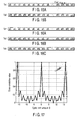
- the AGC preambles 105A to 105D shown in FIG. 12 (a), (b), (c) and (d) are each formed of a signal sequence including a plurality of time-domain samples (ten samples in the case of FIG. 12).
- the AGC preambles 105A to 105D shown in FIG. 12 (a), (b), (c) and (d) are formed by cyclic shifting the samples in time domain of a single signal sequence.
- a signal sequence acquired by cyclic shifting of the samples in time domain of an AGC preamble sequence transmitted from a certain reference antenna is an AGC preamble sequence transmitted from another antenna.
- the AGC preamble sequence 105B transmitted from the antenna Tx2 is (a1, a2, ..., a9, a0), which is acquired by cyclic shifting, by one sample, the temporal positions of the samples of the AGC preamble 105A transmitted from the reference antenna Tx1.
- the AGC preamble 105C transmitted from the antenna Tx3 is acquired by cyclic shifting, by two samples, the temporal positions of the samples of the AGC preamble 105A transmitted from the reference antenna Tx1.
- the AGC preamble 105D transmitted from the antenna Tx4 is acquired by cyclic shifting, by three samples, the temporal positions of the samples of the AGC preamble 105A transmitted from the antenna Tx1 as reference.
- the AGC preambles 105A to 105D are formed of signal sequences identical to each other, they may well interfere with each other during transmission. Such interference may cause an electric field similar to that occurring when directional antenna transmission is performed, depending upon a multipath state or receiving point. As a result, a null point may occur. In other words, there may occur a receiving point at which none of the AGC preambles can be received and the receiving level may not accurately be measured.
- a multipath formed of signal sequences i.e., the AGC preambles 105A to 105D
- the AGC preambles 105A to 105D are acquired by cyclic shifting the temporal positions of their samples.
- the probability of occurrence of a reduction in the receiving level of another sample is low. Therefore, accurate receiving level measurement is realized, which enhances the receiving performance of the wireless receiving device.
- a communication system can be realized which is not against a protocol, CSMA/CA (Carrier Sense Multiple Access with Collision Avoidance), stipulated in IEEE 802.11.
- CSMA/CA Carrier Sense Multiple Access with Collision Avoidance
- FIG. 13 (a) to (d) show other examples of the AGC preambles 105A to 105D.
- the AGC preambles 105A to 105D shown in FIG. 12 (a) to (d) are time-domain signal sequences acquired by cyclic shifting the temporal positions of their samples to each other.
- the AGC preambles 105A to 105D shown in FIG. 13 (a) to (d) are frequency-domain signal sequences, and have different frequency components.
- f0 to f15 indicate subcarrier frequencies, and the hatched subcarriers carry signals, while non-hatched subcarriers do not carry signals.
- the AGC preamble 105A transmitted from the antenna Tx1 is formed of subcarriers f0, f4, f8 and f12.
- the AGC preamble 105B transmitted from the antenna Tx2 is formed of subcarriers f1, f5, f9 and f13.
- the AGC preamble 105C transmitted from the antenna Tx3 is formed of subcarriers f2, f6, f10 and f14.
- the AGC preamble 105D transmitted from the antenna Tx4 is formed of subcarriers f3, f7, f11 and f15.
- the subcarriers transmitted from the antenna Tx1 are not sent by any other antenna.
- the subcarriers transmitted from the antenna Tx2 are not sent by any other antenna.
- the AGC preambles 105A to 105D are transmitted after they are transformed into time-domain signal sequences by inverse fast Fourier transform (IFFT) or discrete Fourier transform (DFT).
- IFFT inverse fast Fourier transform
- DFT discrete Fourier transform
- a memory 202 stores, as AGC preambles, data concerning the frequency-domain signal sequences as shown in FIG. 13 (a) to (d).
- the frequency-domain signal sequence data read from the memory 202 is transformed into time-domain signal sequences by an IFFT circuit 206, and input to a digital modulator 203.
- the digital modulator 203 may incorporate the function of the IFFT circuit 206.
- the memory 202 may pre-store time-domain signal sequence data into which the frequency-domain signal sequence data shown in FIG. 13 (a) to (d) is transformed. In this case, the IFFT circuit 206 is not needed.
- the wireless receiving device can perform accurate receiving level measurement and hence exhibit high receiving performance.
- D/A digital-to-analog
- digital modulator 203 performs such D/A conversion instead of the transmission units 204A to 204D.
- analog-to-digital (A/D) conversion is performed in receiving units 302A to 302D respectively. But, it can be modified that such A/D conversion is performed by digital demodulator 304 instead of the units 302A to 302D.
- the short-preamble sequence 101, first long-preamble sequence 102, first signal field (SIGNAL) 103 and second signal field (SIGNAL 2) 104 are transmitted from antenna Tx1 as shown in FIG. 1. But, it can be possible that such preamble signal is transmitted from at least one transmitted antenna. It is possible that each of the second long-preamble sequences may have different frequency components like the AGC preambles 105A to 105D shown in FIG. 13 (a) to (d).
- a still another sequence of the AGC preamble is shown in the following equation (5).
- the equation (5) represents the sequence of the AGC preamble in the frequency domain when the number of subcarriers used for the wireless transmitting device is 52.
- HTS - 26 , 26 0 , 0 , 1 + j , 0 , 0 , 0 , 0 , - 1 - j , 0 , 0 , 1 + j , 0 , 0 , 0 , 0 , - 1 - j , 0 , 0 , 0 , - 1 - j , 0 , 0 , 0 , 1 + j , 0 , 0 , 0 , 0 , 0 , 0 , 0 , 0 , - 1 - j , 0 , 0 , 0 , 1 + j , 0 , 0 , 0
- HTS in the equation (5) represented in the frequency domain is transmitted from the first transmit antenna T x1 .
- HTS transmitted from other antennas is formed by a cyclic shift of the signal from antenna Tx1 in the time domain as is shown in FIG. 12, in this example the sequence which is acquired by cyclic shifting the sequence of the equation (5) in the time domain as is shown, for example, in FIG. 15A and 15B or FIG. 16A, 16B and 16C is used.
- the cyclic shift in the time domain is equivalent to a phase rotation in the frequency domain.
- N Tx represents the total number of the transmit antennas
- i Tx represents the antenna's number
- ⁇ F represents a subcarrier interval
- "j" is an imaginary number
- Ns represents the range of the subcarriers for use, in the example of the equation (5), it shows that a part of subcarriers which is in the range of -26 th and 26 th is used for transmission of the AGC preamble.
- q k represents the phase rotation vector for k-th subcarrier.
- HTS k represents frequency components of the AGC preamble sequence, which are used for the k-th subcarrier, i.e., HTS K represents of using the k-th components of HTSs shown in the equation (5).
- FIG. 17 shows a cross-correlation value between the sequence acquired by converting HTS of the equation (5) onto the time domain and the sequence acquired by cyclic shifting the converted HTS. More precisely, FIG. 17 shows the cross-correlated value of the sequence acquired by converting HTS of the equation (5) onto the time domain and a part of the sequence of the converted HTS. Since one cycle of the sequence acquired by converting HTS of the equation (5) onto the time domain has 16 samples, the part of the cyclic-shifted sequence mentioned above also has the length of 16 samples.
- FIG. 17 indicates the value of D and the Y-axis indicates the cross correlation value.
- N Tx the total number of the transmit antennas
- the signals transmitted from the antennas T x1 , T x2 are uncorrelated, so each signal arrives at the receiver without interfering each other.
- the transmission power from the antennas Tx1, Tx2 can therefore be measured precisely at the receiver side, then the AGC in receiving with a plurality of antennas at the receiver side, i.e., MIMO-AGC will be possible.
- D is set to 4 to allow the cross correlation value to be possibly small as is shown in FIG. 16A, 16B and 16C.
- the settled amount of the cyclic shift D is stored in the memory (referred to 202 in FIG. 2) in the wireless transmission device.
- the number of the antennas is 4 in the example of the transmission device of FIG. 2, however, such approach is useful if the number of the antennas for use can be changed as necessary.
- a set of the signal sequences of pre-cyclic shifted AGC preamble may be store in the memory, and the set of the signal sequences may be retrieved from the memory in accordance with the number of the antennas for use. That is, given that the number of the antennas for use would be 2, the set of signal sequences of the AGC preamble shown in FIG. 15 will be stored in the memory. Given that the number would be 3, the set of signal sequences of the AGC preamble shown in FIG. 16 will be stored in the memory. It also makes possible to transmit the best-suited sequence of the AGC preamble in accordance with the number of the antennas for use.
Landscapes
- Engineering & Computer Science (AREA)
- Computer Networks & Wireless Communication (AREA)
- Signal Processing (AREA)
- Radio Transmission System (AREA)
- Mobile Radio Communication Systems (AREA)
Applications Claiming Priority (1)
| Application Number | Priority Date | Filing Date | Title |
|---|---|---|---|
| JP2005160443A JP4342477B2 (ja) | 2005-05-31 | 2005-05-31 | 無線送信装置及び無線受信装置 |
Publications (2)
| Publication Number | Publication Date |
|---|---|
| EP1729430A2 true EP1729430A2 (de) | 2006-12-06 |
| EP1729430A3 EP1729430A3 (de) | 2007-11-21 |
Family
ID=36691526
Family Applications (1)
| Application Number | Title | Priority Date | Filing Date |
|---|---|---|---|
| EP06251418A Withdrawn EP1729430A3 (de) | 2005-05-31 | 2006-03-16 | Drahtlose Sendevorrichtung zur Paketübertragung und Verfahren zur Benutzung von mehreren Antennen |
Country Status (4)
| Country | Link |
|---|---|
| US (1) | US20060270364A1 (de) |
| EP (1) | EP1729430A3 (de) |
| JP (1) | JP4342477B2 (de) |
| CN (1) | CN1874183A (de) |
Cited By (1)
| Publication number | Priority date | Publication date | Assignee | Title |
|---|---|---|---|---|
| EP2395678B1 (de) * | 2010-06-09 | 2018-10-31 | Avago Technologies General IP (Singapore) Pte. Ltd. | Short-training-field (stf) mit zyklischer schaltverzögerung zur orthogonalen frequenzteilungssignalisierung innerhalb drahtloser mehrfachbenutzer-, mehrfachzugriff- und/oder mimo-kommunikationen |
Families Citing this family (26)
| Publication number | Priority date | Publication date | Assignee | Title |
|---|---|---|---|---|
| US8743837B2 (en) * | 2003-04-10 | 2014-06-03 | Qualcomm Incorporated | Modified preamble structure for IEEE 802.11A extensions to allow for coexistence and interoperability between 802.11A devices and higher data rate, MIMO or otherwise extended devices |
| US7916803B2 (en) | 2003-04-10 | 2011-03-29 | Qualcomm Incorporated | Modified preamble structure for IEEE 802.11a extensions to allow for coexistence and interoperability between 802.11a devices and higher data rate, MIMO or otherwise extended devices |
| JP4212548B2 (ja) | 2003-12-26 | 2009-01-21 | 株式会社東芝 | 無線送信装置、無線受信装置、無線送信方法及び無線受信方法 |
| JP4043442B2 (ja) | 2004-01-09 | 2008-02-06 | 株式会社東芝 | 無線送信装置、無線受信装置、無線送信方法及び無線受信方法、無線通信システム |
| US7742533B2 (en) | 2004-03-12 | 2010-06-22 | Kabushiki Kaisha Toshiba | OFDM signal transmission method and apparatus |
| HUE031812T2 (en) * | 2004-05-27 | 2017-08-28 | Qualcomm Inc | Modified prefix structure for IEEE 802.11A extensions to enable coexistence and interoperability between 802.11A devices and higher data rate, MIMO or otherwise extended devices |
| JP4256301B2 (ja) * | 2004-05-28 | 2009-04-22 | 株式会社東芝 | 無線通信装置 |
| JP4138702B2 (ja) * | 2004-06-09 | 2008-08-27 | 株式会社東芝 | 無線通信装置 |
| JP2006054705A (ja) * | 2004-08-12 | 2006-02-23 | Toshiba Corp | 無線送信装置及び無線送信方法 |
| EP1906568B1 (de) * | 2005-08-26 | 2015-04-01 | Panasonic Intellectual Property Corporation of America | Funksendevorrichtung und funksendeverfahren |
| US8351518B2 (en) * | 2005-09-30 | 2013-01-08 | Sharp Kabushiki Kaisha | Wireless transmitting apparatus, wireless receiving apparatus, wireless communication system, wireless transmitting method and wireless receiving method |
| JP4673237B2 (ja) * | 2006-02-27 | 2011-04-20 | 富士通株式会社 | 無線受信装置 |
| JP2008193223A (ja) * | 2007-02-01 | 2008-08-21 | Sanyo Electric Co Ltd | 推定方法ならびにそれを利用した推定装置、受信装置および無線受信システム |
| JP2008193222A (ja) * | 2007-02-01 | 2008-08-21 | Sanyo Electric Co Ltd | 推定方法ならびにそれを利用した推定装置、受信装置および受信システム |
| US8090061B1 (en) * | 2007-02-27 | 2012-01-03 | Qualcomm Atheros, Inc. | AGC control for MIMO systems |
| CN101867551B (zh) * | 2009-06-03 | 2015-09-02 | 开曼群岛威睿电通股份有限公司 | 多输入多输出正交频分多址技术和前同步码设计 |
| US20110075630A1 (en) * | 2009-09-25 | 2011-03-31 | Eilon Riess | Enabling inter frequency assignment scanning while remaining at one frequency |
| JP5625395B2 (ja) * | 2010-03-03 | 2014-11-19 | ソニー株式会社 | 無線通信装置、無線通信方法および無線通信システム |
| US8681890B2 (en) * | 2010-06-07 | 2014-03-25 | Entropic Communications, Inc. | Method and apparatus for real time multiplexing with receiver and antenna array elements |
| JP5514324B2 (ja) * | 2010-11-02 | 2014-06-04 | パナソニック株式会社 | 通信システム |
| CN103124209B (zh) * | 2011-11-18 | 2016-06-29 | 华为技术有限公司 | 业务数据的发送、接收方法和装置 |
| US9544041B2 (en) * | 2013-08-22 | 2017-01-10 | Cisco Technology, Inc. | Independent and concurrent automatic gain control for wireless communication and spectral intelligence |
| CN109863643B (zh) * | 2016-10-13 | 2021-06-11 | 瑞典爱立信有限公司 | 用于波束成形的方法和设备 |
| CN110830196B (zh) * | 2018-08-09 | 2021-11-02 | 大唐移动通信设备有限公司 | 一种时长配置方法、装置及设备 |
| US10904059B2 (en) * | 2018-11-02 | 2021-01-26 | Qualcomm Incorporated | Control channel for vehicle-to-everything (V2X) communication |
| CN110752898B (zh) * | 2019-09-29 | 2022-06-10 | 武汉船舶通信研究所(中国船舶重工集团公司第七二二研究所) | 基于多天线接收信号的处理方法和装置 |
Family Cites Families (20)
| Publication number | Priority date | Publication date | Assignee | Title |
|---|---|---|---|---|
| US8320301B2 (en) * | 2002-10-25 | 2012-11-27 | Qualcomm Incorporated | MIMO WLAN system |
| US6940843B2 (en) * | 2003-02-14 | 2005-09-06 | Cisco Technology, Inc. | Selecting an access point according to a measure of received signal quality |
| US7916803B2 (en) * | 2003-04-10 | 2011-03-29 | Qualcomm Incorporated | Modified preamble structure for IEEE 802.11a extensions to allow for coexistence and interoperability between 802.11a devices and higher data rate, MIMO or otherwise extended devices |
| US7277685B2 (en) * | 2003-04-17 | 2007-10-02 | Realtek Semiconductor Corp. | Automatic gain control of multiple antenna OFDM receiver |
| EP1642434B1 (de) * | 2003-06-30 | 2017-08-02 | Avago Technologies General IP (Singapore) Pte. Ltd. | Verfahren und vorrichtungen zur rückwarts-kompatiblen kommunikation in einem mimo-kommunikationssystem mit empfänger von niedrigerer ordnung |
| EP1639776B1 (de) * | 2003-06-30 | 2015-08-26 | Agere Systems, Inc. | Verfahren und vorrichtungen zur rückwärtskompatiblen kommunikation in einem mehrantennen-kommunikationssystem unter verwendung von zeitorthogonalen symbolen |
| US6922549B2 (en) * | 2003-10-31 | 2005-07-26 | Cisco Technology, Inc. | Error vector magnitude selection diversity metric for OFDM |
| US7809020B2 (en) * | 2003-10-31 | 2010-10-05 | Cisco Technology, Inc. | Start of packet detection for multiple receiver combining and multiple input multiple output radio receivers |
| US7245674B2 (en) * | 2003-11-28 | 2007-07-17 | Texas Instruments Incorporated | Method and system for providing low power WLAN receiver |
| JP4212548B2 (ja) * | 2003-12-26 | 2009-01-21 | 株式会社東芝 | 無線送信装置、無線受信装置、無線送信方法及び無線受信方法 |
| US7450489B2 (en) * | 2003-12-30 | 2008-11-11 | Intel Corporation | Multiple-antenna communication systems and methods for communicating in wireless local area networks that include single-antenna communication devices |
| JP4043442B2 (ja) * | 2004-01-09 | 2008-02-06 | 株式会社東芝 | 無線送信装置、無線受信装置、無線送信方法及び無線受信方法、無線通信システム |
| US7457369B2 (en) * | 2004-01-29 | 2008-11-25 | Texas Instruments Incorporated | Scalable gain training generator, method of gain training and MIMO communication system employing the generator and method |
| KR20070020033A (ko) * | 2004-05-13 | 2007-02-16 | 코닌클리케 필립스 일렉트로닉스 엔.브이. | Ieee 802.11n에 관한 상이한 데이터 속도를 구비한다중 수신기 집합(mra) |
| HUE031812T2 (en) * | 2004-05-27 | 2017-08-28 | Qualcomm Inc | Modified prefix structure for IEEE 802.11A extensions to enable coexistence and interoperability between 802.11A devices and higher data rate, MIMO or otherwise extended devices |
| US8077592B2 (en) * | 2004-06-22 | 2011-12-13 | Intellectual Ventures I Llc | Packet processing systems and methods |
| EP3537681B1 (de) * | 2004-06-24 | 2020-10-07 | Apple Inc. | Präambeln in einem ofdma-system |
| JP2006054705A (ja) * | 2004-08-12 | 2006-02-23 | Toshiba Corp | 無線送信装置及び無線送信方法 |
| US7239659B2 (en) * | 2004-11-04 | 2007-07-03 | Motorola, Inc. | Method and apparatus for channel feedback |
| KR101166011B1 (ko) * | 2005-02-08 | 2012-07-17 | 퀄컴 인코포레이티드 | 빔형성 및 레가시 디바이스의 공존을 허용하는 무선 메시징프리앰블 |
-
2005
- 2005-05-31 JP JP2005160443A patent/JP4342477B2/ja not_active Expired - Fee Related
- 2005-08-11 US US11/201,385 patent/US20060270364A1/en not_active Abandoned
-
2006
- 2006-03-16 EP EP06251418A patent/EP1729430A3/de not_active Withdrawn
- 2006-03-27 CN CNA2006100676927A patent/CN1874183A/zh active Pending
Cited By (1)
| Publication number | Priority date | Publication date | Assignee | Title |
|---|---|---|---|---|
| EP2395678B1 (de) * | 2010-06-09 | 2018-10-31 | Avago Technologies General IP (Singapore) Pte. Ltd. | Short-training-field (stf) mit zyklischer schaltverzögerung zur orthogonalen frequenzteilungssignalisierung innerhalb drahtloser mehrfachbenutzer-, mehrfachzugriff- und/oder mimo-kommunikationen |
Also Published As
| Publication number | Publication date |
|---|---|
| US20060270364A1 (en) | 2006-11-30 |
| JP2006339887A (ja) | 2006-12-14 |
| JP4342477B2 (ja) | 2009-10-14 |
| CN1874183A (zh) | 2006-12-06 |
| EP1729430A3 (de) | 2007-11-21 |
Similar Documents
| Publication | Publication Date | Title |
|---|---|---|
| EP2538576B1 (de) | Drahtlose Sende- und Empfangsvorrichtung und Verfahren | |
| EP1729430A2 (de) | Drahtlose Sendevorrichtung zur Paketübertragung und Verfahren zur Benutzung von mehreren Antennen | |
| EP1626550A2 (de) | Sendevorrichtung und -methode in einem MIMO System | |
| JP5599496B2 (ja) | 無線通信装置、無線通信端末および無線通信方法 |
Legal Events
| Date | Code | Title | Description |
|---|---|---|---|
| PUAI | Public reference made under article 153(3) epc to a published international application that has entered the european phase |
Free format text: ORIGINAL CODE: 0009012 |
|
| 17P | Request for examination filed |
Effective date: 20060321 |
|
| AK | Designated contracting states |
Kind code of ref document: A2 Designated state(s): AT BE BG CH CY CZ DE DK EE ES FI FR GB GR HU IE IS IT LI LT LU LV MC NL PL PT RO SE SI SK TR |
|
| AX | Request for extension of the european patent |
Extension state: AL BA HR MK YU |
|
| PUAL | Search report despatched |
Free format text: ORIGINAL CODE: 0009013 |
|
| AK | Designated contracting states |
Kind code of ref document: A3 Designated state(s): AT BE BG CH CY CZ DE DK EE ES FI FR GB GR HU IE IS IT LI LT LU LV MC NL PL PT RO SE SI SK TR |
|
| AX | Request for extension of the european patent |
Extension state: AL BA HR MK YU |
|
| AKX | Designation fees paid |
Designated state(s): DE FR GB |
|
| STAA | Information on the status of an ep patent application or granted ep patent |
Free format text: STATUS: THE APPLICATION HAS BEEN WITHDRAWN |
|
| 18W | Application withdrawn |
Effective date: 20100407 |