EP1729526B1 - Procédé et dispositif pour le réglage de la couleur par l'utilisation d'un tableau de consultation à trois dimensions - Google Patents
Procédé et dispositif pour le réglage de la couleur par l'utilisation d'un tableau de consultation à trois dimensions Download PDFInfo
- Publication number
- EP1729526B1 EP1729526B1 EP06252851A EP06252851A EP1729526B1 EP 1729526 B1 EP1729526 B1 EP 1729526B1 EP 06252851 A EP06252851 A EP 06252851A EP 06252851 A EP06252851 A EP 06252851A EP 1729526 B1 EP1729526 B1 EP 1729526B1
- Authority
- EP
- European Patent Office
- Prior art keywords
- imaging
- correction
- data
- color
- lut
- Prior art date
- Legal status (The legal status is an assumption and is not a legal conclusion. Google has not performed a legal analysis and makes no representation as to the accuracy of the status listed.)
- Active
Links
Images












Classifications
-
- H—ELECTRICITY
- H04—ELECTRIC COMMUNICATION TECHNIQUE
- H04N—PICTORIAL COMMUNICATION, e.g. TELEVISION
- H04N23/00—Cameras or camera modules comprising electronic image sensors; Control thereof
- H04N23/80—Camera processing pipelines; Components thereof
- H04N23/84—Camera processing pipelines; Components thereof for processing colour signals
- H04N23/88—Camera processing pipelines; Components thereof for processing colour signals for colour balance, e.g. white-balance circuits or colour temperature control
Definitions
- the present invention contains subject matter related to Japanese Patent Application JP 2005-160841 filed in the Japanese Patent Office on June 1, 2005 , the entire contents of which being incorporated herein by reference.
- the present invention relates to an imaging device and a method of processing an imaging result in an imaging device, and can be applied to an electronic still camera for example.
- the invention employs a three-dimensional look-up table and corrects an imaging result by use of the three-dimensional look-up table, to thereby enable image quality to be readily and flexibly corrected, with the deterioration of the image quality being avoided effectively.
- an electronic still camera that allows image quality to be variously set according to color mode selection, and thus can offer wide compatibility with imaging environments, user's preferences, etc.
- image data obtained by an imaging element is subjected to auto white balance adjustment, grayscale correction, and chroma correction, followed by being recorded in a memory card as a recording medium in a format compatible with DCF (Design rule for Camera File System).
- DCF Design rule for Camera File System
- the grayscale correction is to correct grayscales of image data defined by red, green and blue (RGB) with use of a nonlinear function.
- the grayscale correction e.g., the sense of brightness and the sense of contrast of image quality are operated in order to bring the contrast of an imaging result close to that of actual look of the imaged object.
- Various configurations relating to the correction have been proposed in e.g., Japanese Patent Laid-open No. 2004-104464 .
- image quality is set based on a color mode, parameters defining the nonlinear function are changed in the grayscale correction.
- the chroma correction is processing in which image data based on RGB is converted into image data based on a luminance signal and color difference signals, and then the image data based on a luminance signal and color difference signals is linearly transformed on a color difference plane defined by color difference signals.
- the chroma correction is applied to tint adjustment and chroma adjustment in which chroma is increased to offer impressive image quality or is decreased to prevent grayscale error.
- image quality is set based on a color mode, parameters defining the linear transformation processing are changed in the chroma correction.
- grayscale correction and chroma correction are processing for converting the entire color space, and therefore involve a difficulty in adjusting only a limited area of the color space. Accordingly, flexible correction of image quality is impossible. For example, adjusting the tint of the red region leads to an unnatural skin color, and operating the tint of the yellow region affects the green region. As a result, adjustment operations for the respective representative colors have an effect on each other, and therefore adequate adjustment of all the representative colors is impossible.
- the grayscale correction and chroma correction cannot offer processing in which the existence of these opposite colors is taken into consideration, and thus readily cause the deterioration of image quality due to the color saturation.
- WO 2005/027040 A discloses an image processing device for performing color processing of an image signal.
- a profile creation portion is provided for creating a new color transformation profile that achieves a predetermined color processing to a predetermined degree of processing.
- the present invention is made in consideration of the above-described problems, and an object thereof is to provide an imaging device and a method of processing an imaging result in an imaging device for enabling image quality to be corrected readily and flexibly, with the deterioration of the image quality being avoided effectively.
- image quality can be corrected readily and flexibly with the deterioration thereof being avoided effectively.
- Fig. 2 is a perspective view illustrating an electronic still camera according to a first embodiment of the invention.
- the electronic still camera 1 is formed into a rectangular thin plate shape, and has a lens and so forth on the front face thereof.
- the electronic still camera 1 has a liquid crystal display 2 for monitoring an imaging result on its backside illustrated in the drawing.
- a touch panel 3 is provided on the display screen of the liquid crystal display 2.
- the electronic still camera 1 also has on its backside a rotary operating element 4 that can be pressed, and an operating element 5 for selecting a direction and making a decision.
- the electronic still camera 1 has a slide switch 6 on its side face. The operation of these operating elements 4 to 6 also permits the acceptance of operations such as menu selection.
- Fig. 3 is a plan view illustrating the indication of a menu for selecting a color mode in association with the operation of the touch panel 3 and the operating elements 4 to 6.
- the color modes are image quality correction modes according to imaging environments and user's preferences.
- the electronic still camera 1 displays a menu including items: image quality correction mode (color mode), ISO sensitivity, flash, and resolution. Selecting an item from the menu leads to indication of the corresponding sub menu.
- Fig. 3 shows the case where the item for image quality correction modes has been selected.
- a sub menu including portrait, Vivid (lamp), Vivid (cloudy), Vivid (sunny), filmlike as color modes is indicated.
- a desired color mode can be selected through the selection from this sub menu including these color modes.
- a user interface can be made so that image quality can be adjusted more finely compared with the correction of image quality merely by use of white balance adjustment and so on.
- Fig. 4 is a block diagram illustrating the electronic still camera according to the first embodiment of the invention.
- an imaging element 12 is provided with e.g., a color filter of a primary control system, and outputs an imaging result of an optical image that is formed on the imaging plane through a lens (not shown).
- the electronic still camera 1 subjects an output signal from the imaging element 12 to correlated double sampling and other processing, and then subjects the resultant signal to analog-to-digital conversion to thereby produce image data defined by primary color signals.
- the image data is input to a demosaic processor 13.
- the demosaic processor 13 executes interpolation processing for this image data to thereby correct the spatial phase of the imaging result corresponding to the color filter provided in the imaging element 12, and output the resultant image data.
- a linear matrix part 14 executes arithmetic processing of the image data output from the demosaic processor 13 to thereby increase the color purity of the image data and output the resultant image data.
- An auto white balance adjuster (AWB) 15 implements auto white balance adjustment of output data from the linear matrix part 14, and outputs the resultant data.
- a gamma corrector (Y correction) 16 executes gamma correction of the output data from the auto white balance adjuster 15, and outputs the corrected data.
- a YCC converter 17 converts the image data (R1, G1, B1) composed of primary color signals output from the gamma corrector 16 into image data (Y1, Cb1, Cr1) defined by on a luminance signal and color difference signals through arithmetic processing in accordance with Equation 1.
- M ⁇ 1 0.2990 0.5870 0.1140 ⁇ 0.1687 ⁇ 0.3313 0.5000 0.5000 ⁇ 0.4187 ⁇ 0.0813
- a color difference matrix 18 implements matrix arithmetic processing of Equation 2 for, of the image data (Y1, Cb1, Cr1) based on a luminance signal and color difference signals, image data (Cb1, Cr1) defined by color difference signals.
- the color difference matrix 18 executes chroma correction processing therefor and outputs image data (Cb2, Cr2) resulting from the processing.
- a three-dimensional look-up table block (3D-LUT block) 19 corrects the image data (Cb2, Cr2) made up of color difference signals output from the color difference matrix 18 and the image data Y1 defined by a luminance signal output from the YCC converter 17, and outputs the corrected data.
- the liquid crystal display 2 displays an image for monitoring based on the image data output from the 3D-LUT block 19.
- a controller 21 is a unit for controlling the operation of the entire electronic still camera 1, and executes a processing program recorded in a memory 22 to thereby switch the entire operation in response to operations of the touch panel 3 and various operating elements 4 to 6.
- the controller 21 sets data for correction (hereinafter, correction data) recorded in the memory 22 in the 3D-LUT block 19 according to this color mode selection.
- the memory 22 stores a processing program to be executed by the controller 21, and plural kinds of correction data corresponding to color modes included in the electronic still camera 1.
- the correction data is thus set in the 3D-LUT block 19, the indication on the liquid crystal display 2 is switched so that the completion of the setting is notified of the user.
- the processing program relating to the 3D-LUT block 19 is provided in the camera 1 by preinstall.
- the program may be provided through downloading over a network such as the Internet, or may be provided after being recorded in a recording medium such as an optical disk, a magnetic disk or a memory card.
- Fig. 1 is a block diagram illustrating the 3D-LUT block 19 together with related configurations.
- the 3D-LUT block 19 corrects input image data (Y2, Cb2, Cr2) in a color space by use of a correction vector as shown in Fig. 5 , and outputs image data D3 with a target value.
- grid points arranged in a matrix are set in the color space defined by the input image data (Y2, Cb2, Cr2) as shown in Fig. 6 .
- Correction vectors of the grid points are set depending on a selected color mode under control by the controller 21. As shown in Figs.
- the 3D-LUT block 19 creates a correction vector for the sampling value of the input image data (Y2, Cb2, Cr2) based on correction vectors set for eight grid points surrounding the sampling point of the input image data (Y2, Cb2, Cr2).
- the 3D-LUT block 19 then corrects the sampling value of the input image data (Y2, Cb2, Cr2) by use of the created correction vector.
- the grid point having the smallest sampling value of the eight grid points around the sampling point of the input image data (Y2, Cb2, Cr2) is defined as a reference grid point g1.
- an area determiner 31 makes a determination as to the sampling value of the input image data (Y2, Cb2, Cr2), to thereby detect the reference grid point g1 for the input image data ( Fig. 7 ).
- the area determiner 31 detects an offset p from the reference grid point g1 for the sampling value of the input image data (Y2, Cb2, Cr2).
- the offset p is a deviation between the sampling value of the input image data (Y2, Cb2, Cr2) and the reference grid point g1.
- grids points are set in the color space defined by the input image data (Y2, Cb2, Cr2) of m bits in such a manner that 2 n + 1 (n ⁇ m) grid points are uniformly distributed on each axis.
- the area determiner 31 detects the reference grid point g1 from the n most significant bits of the input image data (Y2, Cb2, Cr2), and detects the offset p from the m-n least significant bits thereof, as expressed by Equations 4 and 5.
- an address decoder 32 Based on information on the reference grid point g1 detected by the area determiner 31, an address decoder 32 sequentially produces and outputs addresses necessary for access to correction data relating to the eight grid points surrounding the input image data (Y2, Cb2, Cr2).
- the grid points are recorded in a three-dimensional look-up table (3D-LUT) 33.
- the coordinates of these eight grid points g1 to g8 are expressed by Equation 6, when the coordinate of the reference grid point g1 is (x, y, z).
- the 3D-LUT 33 sequentially outputs correction vectors G1 to G8 set for the eight grid points surrounding the input image data (Y2, Cb2, Cr2) in accordance with the address data output from the address decoder 32.
- An adder 36 adds the correction vector V to the original input image data (Y2, Cb2, Cr2) based on arithmetic processing of Equation 10, and outputs output image data D3 (Y3, Cb3, Cr3).
- Figs. 9 and 10 are flowcharts showing processing procedures for producing correction vectors of the respective grid points set in the 3D-LUT 33.
- a computer executes these processing procedures in advance to thereby calculate the correction vectors of the respective grid points, and the correction vectors are stored in the memory 22.
- the processing procedures for producing the correction vectors include analysis processing shown in Fig. 9 and conversion processing shown in Fig. 10 .
- the analysis processing is to analyze the correspondence relationship between colors before and after correction.
- the processing sequence proceeds from a step SP1 to a step SP2, where a computer acquires image data arising from imaging of a color chart with use of a predetermined light source as illumination.
- a color chart is a reflectance chart such as Macbeth Color Checker, Macbeth Color Checker SG, or Digital Camera Color Checker.
- used as the light source is a D65 light source.
- the imaging conditions of the respective color modes in the electronic still camera 1 are duplicated.
- the electronic still camera 1 according to the present embodiment is used, and image data (Y1, Cb1, Cr1) output from the YCC converter 17 is used as image data.
- image data Y1, Cb1, Cr1 output from the YCC converter 17
- the computer acquires sampling points from the imaging result of the chart.
- the sampling points are detected in any color space, such as the L*a*b* color space, sYCC color space, or CIECAM, through arithmetic processing in which a function for conversion of the color space is used according to need.
- step SP4 the computer divides the color gamut of the sampling points obtained in the step SP3 into an assemble of Delaunay tetrahedrons on the color space used for the extraction of the sampling points.
- This division is executed by sequentially implementing the following operation: four sampling points that do not exist on the same plane are selected so that no other sampling point exists inside the sphere of which spherical surface includes the four sampling points, and then a tetrahedron of which vertexes are these four sampling points is set.
- This division method allows the gamut to be divided almost stably so that all areas in the gamut overlap with any of the Delaunay tetrahedrons and a gap area that does not overlap with any of the Delaunay tetrahedrons is not generated, without using prior knowledge about the arrangement of the sampling values.
- a spherical surface including four sampling points and surrounding no sampling point includes one or more other sampling points
- the division by use of Delaunay tetrahedrons for the one or more other sampling points is indefinite.
- random small fluctuations E are added to the sampling points so that division is implemented after the sampling points are moved away from the spherical surface.
- the processing sequence of the computer proceeds to a step SP5.
- the computer accepts the setting of the target color after conversion for each sampling point, and sets information on the target colors for the respective sampling values.
- the setting of the target colors is executed by extracting the colors of patches from an imaging result obtained by imaging a color chart with a reference imaging device as a design target.
- the setting of the target colors may be accepted according to an instruction from an operator.
- the computer makes a comparison between an imaging result by the electronic still camera 1 and an imaging result by another imaging device having desired tints and grayscales.
- the computer produces correction data to be set in the 3D-LUT 33 through the subsequent conversion processing shown in Fig. 10 .
- the processing sequence proceeds from a step SP11 to a step SP12, where the computer inputs the color value (input value: xp, yp, zp) of each of the grid points to be set in the 3D-LUT 33 based on the color space used for the detection of the sampling values in the step SP3.
- the computer searches for the Delaunay tetrahedron, set in the step SP4, to which the color of the grid point belongs.
- the Delaunay tetrahedron the computer searches for is the tetrahedron that includes the color value (xp, yp, zp). If the Delaunay tetrahedron including the color value does not exist, the intended Delaunay tetrahedron is the tetrahedron that has a plane adequate for conversion of this color value (xp, yp, zp).
- This searching is executed in such a manner of searching for the Delaunay tetrahedron having the vertexes (x0, y0, z0), (x1, y1, z1), (x2, y2, z2), (x3, y3, z3) that have the relationship of Equation 11 with respect to the input value (xp, yp, zp). Equation 11 ⁇ ⁇ 0 , ⁇ ⁇ 0 , ⁇ ⁇ 0 , ⁇ + ⁇ + ⁇ ⁇ 1
- the processing sequence then proceeds from the step SP13 to a step SP14, where the computer executes arithmetic processing of Equation 13 for the grid point of which corresponding Delaunay tetrahedron including the grid point has been thus detected, to thereby calculate interpolation factors for the grid point from the relationship between the input value and the sampling values of the vertexes of the detected Delaunay tetrahedron.
- interpolation factors are weighting factors to be used for calculation of the correction vector of the grid point in the subsequent step SP15, and are ⁇ , ⁇ , and ⁇ in Equation 13.
- ⁇ ⁇ ⁇ x ⁇ 1 ⁇ x ⁇ 0 x ⁇ 2 ⁇ x ⁇ 0 x ⁇ 3 ⁇ x ⁇ 0 y ⁇ 1 ⁇ y ⁇ 0 y ⁇ 2 ⁇ y ⁇ 0 y ⁇ 3 ⁇ y ⁇ 0 z ⁇ 1 ⁇ z ⁇ 0 z ⁇ 2 ⁇ z ⁇ 0 z ⁇ 3 ⁇ z ⁇ 0 ⁇ 1 ⁇ x ⁇ p ⁇ x ⁇ 0 y ⁇ p ⁇ y ⁇ 0 z ⁇ p ⁇ z ⁇ ⁇ 0
- the computer calculates the target value (xt, yt, zt) of the grid point from the color information, set in the step SP5, regarding the sampling points of the vertexes of the corresponding Delaunay tetrahedron, by linear interpolation in accordance with Equation 14 employing the interpolation factors obtained in the step S14.
- the computer subtracts the original input value (xp, yp, zp) from the calculated target value (xt, yt, zt), to thereby calculate the correction vector V.
- the computer ends the processing procedure for the grid point of which corresponding Delaunay tetrahedron can be detected in the step SP13.
- the processing sequence proceeds from the step SP13 to a step SP18, where the computer detects the plane of a Delaunay tetrahedron adequate for conversion of the input value (xp, yp, zp). Specifically, the computer detects from the planes of the Delaunay tetrahedrons the plane that intersects with the straight line coupling the center of color gamut of the input value with the input value (xp, yp, zp), and is a boundary to the gamut.
- the computer detects the planes each having three vertexes (x1, y1, z1), (x2, y2, z2), (x3, y3, z3) that satisfy the relationship expressed by Equation 15.
- the computer searches for, of the detected planes, the plane closest to the input value (xp, yp, zp).
- (xorg, yorg, zorg) is the coordinate representing the center of the gamut.
- ⁇ ⁇ ⁇ x ⁇ 1 x ⁇ 2 x ⁇ 3 y ⁇ 1 y ⁇ 2 y ⁇ 3 z ⁇ 1 z ⁇ 2 z ⁇ 3 ⁇ 1 ⁇ x ⁇ q ⁇ x ⁇ org y ⁇ q ⁇ y ⁇ org z ⁇ q ⁇ z ⁇ org . ⁇ ⁇ 0 , ⁇ ⁇ 0 , ⁇ ⁇ 0 0 ⁇ 0 0
- a step S19 the computer executes arithmetic processing of Equation 15 with use of the coordinates (x1, y1, z1), (x2, y2, z2), (x3, y3, z3) of vertexes of the plane detected in the step SP18, to thereby calculate interpolation factors ⁇ , ⁇ and ⁇ for the grid point.
- the computer executes interpolation processing expressed by Equation 16 with use of the interpolation factors ⁇ , ⁇ and ⁇ obtained in the step SP19 and the parameter ⁇ obtained through the arithmetic processing of Equation 15.
- the computer calculates the target value (xt, yt, zt) of the grid point from the color information on the vertexes of the plane.
- the processing sequence proceeds to the step S16, where the computer calculates the correction vector of the grid point, followed by the end of the processing.
- the correction vector of each grid point is calculated on each color mode basis, and the data of the calculated correction vectors is recorded in the memory 22.
- the correction vector data recorded in the memory 22 is set in the 3D-LUT 33 depending on the color mode selected by a user.
- the color difference matrix 18 executes chroma correction processing. Accordingly, correction vectors are calculated with the setting of target values in the step SP5 or arithmetic results in the step SP16 being corrected corresponding to the correction by the color difference matrix 18. In addition, target values are set in the step SP5 so that the lightness is not changed due to the chroma correction by the color difference matrix 18.
- the processing of Figs. 9 and 10 may be executed for image data (Cb2, Cr2) composed of color difference signals output from the color difference matrix 18 instead of image data (Cb1, Cr1) composed of color difference signals output from the YCC converter 17.
- correction vectors each having a value that is corrected corresponding to the correction by the color difference matrix 18 may be produced.
- the image data of an imaging result obtained from the imaging element 12 is subjected to processing such as linear matrix, auto white balance, and gamma correction, followed by being converted by the YCC converter 17 into image data (Y1, Cb1, Cr1) defined by a luminance signal and color difference signals.
- image data (Y1, Cb1, Cr1) the image data (Cb1, Cr1) based on color difference signals is subjected to chroma correction by the color difference matrix 18.
- image data (Y2, Cb2, Cr2) based on a luminance signal and color difference signals is created.
- the hue and grayscale of the image data (Y2, Cb2, Cr2) composed of a luminance signal and color difference signals are corrected by the 3D-LUT block 19, and then the resultant data is recorded in a recording medium and is displayed on the liquid crystal display 2.
- the hue and grayscale of the image data (Y2, Cb2, Cr2) defined by a luminance signal and color difference signals are corrected by the 3D-LUT 33 for three components of this image data (Y2, Cb2, Cr2).
- the correction of only the lightness or only the chroma is possible.
- correction without changing the lightness and chroma that have been changed through chroma correction by the color difference matrix 18 is also possible.
- a change of the lightness due to chroma correction can be prevented through the entire processing including the processing by the color difference matrix 18, which correspondingly allows image quality to be corrected with the deterioration thereof being avoided effectively.
- the electronic still camera 1 Provided in the electronic still camera 1 are plural kinds of image quality correction modes corresponding to imaging environments and user's preferences.
- Stored in the memory 22 is plural kinds of correction vector data, which is correction data to be set in the 3D-LUT 33, corresponding to the respective image quality correction modes.
- a menu of color modes ( Fig. 3 ) is displayed on the liquid crystal display 2 in response to operation by a user, and selection from the menu by the user leads to the setting of the corresponding correction data in the 3D-LUT 33. Accordingly, in the electronic still.camera 1, the sampling values of image data are corrected based on the correction data set in the 3D-LUT 33, and the image data having image quality desired by a user is output.
- the electronic still camera 1 can switch image quality variously according to imaging environments and user's preferences, which correspondingly allows the improvement of its usability.
- conversion parameters of the address decoder 32 may also be switched so that assignment to a color space is changed on each image quality correction mode basis.
- grid points are predetermined sampling points among sampling points, in a color space, that can be occupied by image data (Y2, Cb2, Cr2) to be corrected, and correction data for the respective grid points is set in the 3D-LUT 33 ( Figs. 5 to 8 ).
- the area determiner 31 detects the reference grid point g1 and the offset p, which indicate the area and position, defined by the grid points, where the image data (Y2, Cb2, Cr2) exists.
- correction data G1 to G8 of the grid points surrounding the sampling point of the image data (Y2, Cb2, Cr2) is detected.
- the interpolation factor calculator 34 calculates the interpolation factor for interpolation arithmetic processing with use of the correction data G1 to G8. Moreover, interpolation processing with use of this interpolation factor allows the calculation of the correction vector V for the sampling value of the image data (Y2, Cb2, Cr2), and the chroma and lightness of the image data (Y2, Cb2, Cr2) are corrected based on this correction vector V.
- correction amounts are obtained by the 3D-LUT 33 and thus input image data is corrected.
- the 3D-LUT 33 it is also possible for the 3D-LUT 33 to directly supply output values.
- the 3D-LUT 33 outputs correction amounts for image data correction like the present embodiment, the size of the 3D-LUT can be reduced compared with the case where output values are directly output therefrom.
- the correction data to be set in the 3D-LUT 33 is produced as follows. Initially, image data obtained from the imaging of a color chart as a reference image by the electronic still camera 1 with use of reference illumination is sampled. Subsequently, Delaunay tetrahedrons having vertexes corresponding to the sampling values resulting from this sampling are defined, and thus the color space defined by the imaging result is divided by the Delaunay tetrahedrons. The target colors are then set for the sampling values corresponding to the vertexes of the respective Delaunay tetrahedrons.
- the sampling points of grid points are set in the color space divided by the Delaunay tetrahedrons, and then the target colors of the respective grid points are set through interpolation arithmetic processing with use of the target colors set for the vertexes of the Delaunay tetrahedrons.
- the correction data for each grid point is produced based on the target color of the grid point, and is stored in the memory 22.
- the setting of the target colors of the vertex positions of the Delaunay tetrahedrons are set by extracting the colors of patches from an imaging result obtained by imaging a color chart with a reference imaging device as a design target. Correction data is then produced from a comparison between the imaging result by the electronic still camera 1 and that by the reference imaging device.
- correction data to be set in the 3D-LUT 33 can be produced so that easy and ensured adjustment to desired image quality is allowed.
- a 3D-LUT is provided in an image processor and an imaging result is corrected by use of the 3D-LUT, to thereby enable image quality to be readily and flexibly corrected, with the deterioration thereof being avoided effectively.
- plural kinds of correction data are prepared as data to be set in the 3D-LUT, and the setting of data in the 3D-LUT is selectively carried out according to an instruction from a user.
- the type of image quality correction can be switched variously through easy operation.
- a menu of plural kinds of image quality correction modes is displayed on a display unit for accepting selection by a user, and correction data is set in the 3D-LUT in response to the selection by the user, which enables even a user with poor knowledge to easily and surely correct an imaging result to desired image quality.
- Fig. 11 is a plan view illustrating a color mode setting screen in an electronic still camera according to a second embodiment of the invention.
- the electronic still camera according to this embodiment accepts setting of image quality correction through this color mode setting screen, and sets correction data in a 3D-LUT.
- the second embodiment has the same configuration as that of the electronic still camera 1 of the first embodiment, except that a series of processing relating to the color mode setting is different. Therefore, the following description also employs the above-described configurations of Figs. 1 and 4 .
- a menu including items such as image quality correction mode (color mode), ISO sensitivity, flash, and resolution similarly to the above description for the first embodiment ( Fig. 3 ). Selecting from the menu leads to the indication of the corresponding sub menu. Specifically, when the item of image quality correction mode is selected, a sub menu including portrait, Vivid (lamp), Vivid (cloudy), Vivid (sunny), filmlike as color modes is indicated.
- Fig. 12 is a flowchart showing a processing procedure in a controller 21 relating to processing of this image quality setting.
- the processing procedure starts and proceeds from a step SP21 to a step SP22, where the controller 21 accepts the selection of a first color mode.
- the controller 21 accepts the selection of a second color mode.
- the controller 21 accepts the input of two color modes that serve as a basis for an intermediate tone.
- a step SP24 the controller 21 displays a screen for accepting the input of an intermediate tone.
- a bar B of which both ends correspond to the first and second color modes is indicated on the right side of the above-described sub menu for various color modes (see Fig. 11 ), and indicated on the bar B is a cursor K.
- the cursor K is moved through the operation of the touch panel 3 and the like by a user, so that the setting of an intermediate tone is accepted through the setting of position of the cursor K on the bar B. Therefore, when the position of the cursor K on the bar B is brought close to one end, the controller 21 brings an intermediate tone close to the color mode of the one end.
- the controller 21 in response to a decision operation by the user, the controller 21 generates a weighting factor k for the first and second color modes according to the internal division value by the cursor K with respect to the entire length of the bar B.
- step SP27 the controller 21 sets the thus generated correction data L0 for the intermediate tone in the 3D-LUT 33, and then switches the indication on the liquid crystal display 2 to notify a user of the completion of the setting.
- the processing sequence then proceeds to a step SP28, where this processing procedure is ended.
- the thus created correction data for an intermediate tone may be recorded and held, and the image quality correction mode according to this intermediate tone correction data may be utilized as a basis for setting another intermediate tone, or the like.
- correction data arising from interpolation arithmetic is created through interpolation arithmetic processing with plural kinds of correction data recorded in the memory 22, and the correction data arising from interpolation arithmetic is set in a 3D-LUT instead of the correction data recorded in the memory 22.
- image quality correction can be adjusted finely by use of pre-set image quality correction modes as a basis, which correspondingly allows image quality to be corrected flexibly through easy operation.
- the utilization of the correction data arising from interpolation arithmetic can offer various conveniences such as an increase in variations of image quality correction modes.
- Fig. 13 is a block diagram illustrating an electronic still camera 41 according to a third embodiment of the invention.
- the same components as those in the electronic still camera of the first and second embodiments are given the same numerals, and overlapping description thereof will be omitted.
- the electronic still camera 41 automatically selects an image quality correction mode according to imaging conditions that can be detected at the time of imaging.
- the driving of a motor 43 moves a focus lens 42 in the optical axis direction, and thus the focus is adjusted so that an optical image is formed on the imaging plane of an imaging element 12.
- a signal processor 44 serves as a configuration including the above-described components from the demosaic processor 13 to the gamma corrector 16 in the first embodiment.
- the signal processor 44 converts an imaging result obtained from the imaging element 12 into image data, and then processes and outputs the image data. In this series of processing, the signal processor 44 detects the high-pass signal level of the imaging result to thereby acquire information for focus adjustment, and notifies a central processing unit (CPU) 45 of this focus adjustment information. In addition, the signal processor 44 detects the area that is determined to achieve just focus from the focus adjustment information, and notifies the CPU 45 of the distribution of the luminance level in this area.
- CPU central processing unit
- a three-dimensional look-up table (3D-LUT) processor 46 serves as a configuration including the above-described components from the YCC converter 17 to the 3D-LUT block 19 in the first embodiment.
- the 3D-LUT 46 corrects the chroma and lightness of image data and outputs the corrected data. Furthermore, the 3D-LUT 46 processor renews data in the 3D-LUT to be used for the correction of chroma and lightness, under control by the CPU 45.
- the CPU 45 is a controller for controlling the signal processor 44 and the 3D-LUT processor 46.
- the CPU 45 controls the operations of the signal processor 44 and the 3D-LUT processor 46, and produces correction data for the 3D-LUT processor 46.
- the CPU 45 notifies the control microcomputer 48 of information for focus adjustment and information on luminance level distribution that are output from the signal processor 44.
- a motor driver 47 drives the motor 43 under control by the control microcomputer 48.
- the control microcomputer 48 is a controller that controls the operation of the entire electronic still camera 1, and controls the operation of each component in response to the operation of an operating element and the like. In this control, the control microcomputer 48 obtains focus adjustment information from the signal processor 44 via the CPU 45, and drives the motor driver 47 by a so-called hill-climbing method to thereby implement auto-focus control of the lens 42. Through this auto-focus control, the control microcomputer 48 detects the current focus position.
- control microcomputer 48 acquires via the CPU 45 information on the luminance level distribution of the area that is determine to achieve just focus, detected by the signal processor 44. The control microcomputer 48 then determines the luminance level distribution based on the current focus position, and selects an image quality correction mode.
- the image quality correction mode is set to a landscape imaging mode (Vivid).
- the image quality correction mode is set to a person imaging mode (Portrait).
- the image quality correction mode is set to a nighttime imaging mode (Night Mode). In this determination of an image quality correction mode, a pattern matching method can be used.
- the control microcomputer 48 then instructs the CPU 45 to set the 3D-LUT processor 46 according to the image quality correction mode resulting from the determination.
- the above-described setting method of any of the first and second embodiments can be used.
- the image quality correction mode may be set based only on information for auto focus adjustment if the image quality correction mode can be set adequately enough in terms of practical use.
- correction data for a 3D-LUT is switched depending on the current focus position achieved by auto focus adjustment, which is one of imaging conditions that can be detected at the time of imaging.
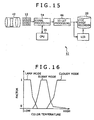
- Fig. 15 is a block diagram illustrating an electronic still camera 51 according to a fourth embodiment of the invention.
- the same components as those in the electronic still cameras of the first, second and third embodiments are given the same numerals, and overlapping description thereof will be omitted.
- the electronic still camera 51 automatically selects an image quality correction mode based on the color temperature of an imaging result before auto white balance adjustment as one of imaging conditions that can be detected at the time of imaging.
- a signal processor 54 serves as a configuration including the above-described components from the demosaic processor 13 to the gamma corrector 16 in the first embodiment.
- the signal processor 54 converts an imaging result obtained from an imaging element 12 into image data, and then processes and outputs the image data.
- the signal processor 54 notifies a central processing unit (CPU) 55 of information on the gains of the respective color signals relating to auto white balance adjustment.
- CPU central processing unit
- the CPU 55 is a controller for controlling the signal processor 54 and a 3D-LUT processor 46.
- the CPU 55 controls the operations of the signal processor 54 and the 3D-LUT processor 46.
- the CPU 55 determines the gains of the respective color signals relating to auto white balance adjustment, informed by the signal processor 54, to thereby detect the color temperature of the imaging target object.
- the CPU 55 renews correction data for the 3D-LUT processor 46 based on the result of the color temperature detection.
- the color temperature of a target object delicately varies depending on which of a sunny condition, a cloudy condition, and a lamp condition an imaging condition is. Therefore, the look of the skin color of a person and the like differs depending on the condition. Accordingly, in the fourth embodiment, an image quality correction mode is selected according to a detected color temperature, and correction data corresponding to the selected image quality correction mode is set in the 3D-LUT processor 46. In this setting, any of the above-described setting methods of the first and second embodiments can be used.
- correction data for a 3D-LUT is switched depending on a color temperature, which is one of imaging conditions that can be detected at the time of imaging.
- the image quality correction mode is switched based on the combination of the above-described determinations regarding an imaging result in the third and fourth embodiments.
- An electronic still camera according to the fifth embodiment has the same configuration as that of the above-described electronic still cameras of the third and fourth embodiments, except for a configuration relating to the combination.
- an electronic still camera provided in an electronic still camera are reference patterns for determining a current focus position, a luminance level and the color temperature of an imaging result, for image quality correction modes M1 to Mn corresponding to plural kinds of correction data stored in a memory 22.
- the electronic still camera determines a current focus position, the luminance level of an area that is determined to achieve just focus, and the color temperature of an imaging result, which are obtained from the imaging result.
- the electronic still camera produces weighting factors k1 to kn for the image quality correction modes M1 to Mn, respectively.
- correction data is produced by determining imaging conditions that can be detected at the time of imaging through pattern matching for each image quality correction mode.
- Fig. 17 is a block diagram illustrating an electronic still camera 61 according to a sixth embodiment of the invention.
- the same components as those in the electronic still cameras of the above-described embodiments are given the same numerals, and overlapping description thereof will be omitted.
- the electronic still camera 61 has the same configuration as that of any of the above-described electronic still cameras of the first to fifth embodiments, except that a 3D-LUT block 69 is provided upstream of a YCC converter 17.
- image quality correction by a 3D-LUT is carried out for image data made up of primary color signals before being subjected to chroma correction by a color difference matrix 18.
- Fig. 18 is a block diagram illustrating an electronic still camera 71 according to a seventh embodiment of the invention.
- the electronic still camera 71 does not include the Y corrector 16, the color difference matrix 18, and the YCC converter 17 (see Fig. 4 ), and processing originally executed by these components, such as chroma correction and grayscale correction, is executed only by a 3D-LUT block 79.
- the electronic still camera according to the seventh embodiment has the same configuration as that of any of the above-described electronic still cameras of the first to fifth embodiments, except that a configuration relating to the 3D-LUT block 79 is different.
- An eighth embodiment of the invention employs any of the configurations of the first to seventh embodiments.
- correction data L1 based on certain reference vectors, recorded and held in a memory 22 is multiplied by a gain k to thereby produce correction data L0 as expressed by Equation 19 and store the correction data L0 in a 3D-LUT 33.
- image quality is adjusted through control of the gain k. This image quality adjustment through control of the gain k may be combined with any of the above-described image quality adjustment methods of the first to seventh embodiments. Equation 19
- L ⁇ 0 k ⁇ L ⁇ 1
- reference correction data is corrected by use of a weighting factor and is stored in the 3D-LUT 33 so that image quality is adjusted through variation in the weighting factor
- advantages of reducing the capacity of memory for correction data and efficiently adjusting color correction amounts can be achieved in addition to advantages similar to those of the above-described embodiments.
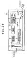
- Fig. 19 is a block diagram illustrating a 3D-LUT block applied to an electronic still camera according to a ninth embodiment of the invention.
- the electronic still camera according to the ninth embodiment has a configuration obtained by applying a 3D-LUT block 89 to the configuration of any of the above-described electronic still cameras of the first to seventh embodiments.
- the 3D-LUT block 89 is provided with a multiplier 89A that weights a correction vector V output from the interpolation arithmetic unit 35 and outputs the weighted vector to an adder 36, and a multiplier 89C that weights the output value from the adder 36 and outputs the weighted value.
- image quality is adjusted through the setting of the weighting factors in these multipliers 89A and 89C, instead of the setting of correction data in the 3D-LUT 33 described above for the first to seventh embodiments, or in addition to the setting of correction data in the 3D-LUT 33.
- the correction vector V is weighted with a weighting factor k by the multiplier 89A, and the weighted vector is added to input image data by the adder 36 as expressed by Equation 20.
- the multiplier 89C may be absent.
- a multiplying circuit 89B may be provided for input image data, and weighting by the multiplier 89B may be executed instead of weighting by the multiplier 89A, or in addition to weighting by the multiplier 89A.
- the weighting by the multiplier 89B provided for input image data instead of weighting by the multiplier 89A is equivalent to the state where an output value from the 3D-LUT 33 is output after being indirectly weighted with a weighting factor.
- This image quality adjustment may be combined with any of the above-described image quality adjustment methods of the first to eighth embodiments.
- an output value from a 3D-LUT is output after being weighted with a weighting factor so that image quality is adjusted through variation in the weighting factor.
- Fig. 20 is a block diagram illustrating a 3D-LUT block applied to an electronic still camera according to a tenth embodiment of the invention.
- the electronic still camera according to the tenth embodiment has a configuration obtained by applying a 3D-LUT block 99 to the configuration of any of the above-described electronic still cameras of the first to seventh embodiments.
- the 3D-LUT block 99 has a configuration in which an output value (Y3, Cb3, Cr3) is directly output from a 3D-LUT 93, and correction data compatible with this configuration is set in the 3D-LUT 93.
- the electronic still camera of the tenth embodiment has the same configuration as that of any of the above-described electronic still cameras of the first to seventh embodiments, except for the configuration in which an output value (Y3, Cb3, Cr3) is directly output from the 3D-LUT 93.
- the configuration of any of the first to tenth embodiments includes a plurality of 3D-LUTs and/or a plurality of 3D-LUT blocks, and image data resulting from the synthesis of output values from these plural components is output.
- the synthesis of output values is executed through weighted addition employing weighting factors, and image quality is adjusted by controlling these weighting factors.
- a 3D-LUT is formed so that processing is allowed also for an imaging result that ranges beyond a color space defined by a format of recording in a recording medium.
- the twelfth embodiment has the same configuration as that of any of the above-described electronic still cameras of the first to eleventh embodiments, except that the configuration relating to the 3D-LUT is different.
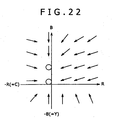
- the thus formed 3D-LUT executes clipping processing based on the maximum value Cmax of color difference signals Cb and Cr of image data as expressed by Equations 21 and 22 as relational expressions.
- the 3D-LUT executes clipping processing for one color difference signal
- the other color difference signal is also subjected to clipping processing by the 3D-LUT so that the hue is not changed.
- the 3D-LUT executes clipping processing for input image data that ranges beyond a color space defined by an output format so that the hue is not changed.
- C ⁇ b ′ ⁇ C ⁇ b , if C ⁇ b ⁇ C ⁇ max , C ⁇ r ⁇ C ⁇ max C ⁇ max C ⁇ r ⁇ C ⁇ b , if C ⁇ b ⁇ C ⁇ r ⁇ C ⁇ max C ⁇ max C ⁇ b ⁇ C ⁇ b , if C ⁇ r ⁇ C ⁇ b ⁇ C ⁇ max Equation 22
- C ⁇ r ′ ⁇ C ⁇ r , if C ⁇ b ⁇ C ⁇ max , C ⁇ r ⁇ C ⁇ max C ⁇ max C ⁇ r ⁇ C ⁇ r , if C ⁇ b ⁇ C ⁇ r ⁇ C ⁇ max C ⁇ max C ⁇ b ⁇ C ⁇ r , if C ⁇ r ⁇ C ⁇ b ⁇ C ⁇ max
- input image data is converted into data within a color space for recording in a recording medium and then is recorded in the recording medium with a change of the hue being prevented as shown in Fig. 21 .
- the processing for data outside a color space is also applicable to image data that is recorded in a recording medium as data defined by color signals.
- input image data of an imaging result composed of primary color signals is processed in a matrix arithmetic unit so as to be subjected to mapping in an sRGB gamut, followed by being input to a 3D-LUT block.
- RGB values of grid points obtained from an imaging result by an electronic still camera of the twelfth embodiment are converted into L*a*b* values, and correction data to be set in the 3D-LUT is produced based on the RGB values after being subjected to any gamut mapping processing, obtained in the L*a*b* space.
- the sampling values of input image data are corrected so that the respective sampling points in the RGB color space are displaced toward the center of the space with a change of the hue defined by RGB values being prevented.
- the processing of correcting the range of a color space for offering a compatibility with an output format can be widely applied to various ways of outputting image data.
- this processing is also applicable to the case where output image data is limited to data within a color space that can be displayed on the liquid crystal display 2.
- clipping is executed for an imaging result that ranges beyond the range of a color space defined by a recording format of recording in a recording medium so that the hue is not changed, and then the processed data is output.
- an electronic still camera In an electronic still camera according to a thirteenth embodiment of the invention, three axes relating to processing in a 3D-LUT are designed to have different resolutions.
- the thirteenth embodiment has the same configuration as that of any of the above-described electronic still cameras of the first to twelfth embodiments, except that the configuration concerning the 3D-LUT is different.
- the numbers of grid points on the respective axes concerning the setting of the 3D-LUT are set to 2 p +1, 2 q +1, and 2 r +1, respectively.
- correction data compatible with this setting is produced.
- an area determiner 31 and an interpolation factor calculator 34 process input image data by arithmetic processing in accordance with Equations 23 to 25 instead of arithmetic processing of Equations 4, 5 and 7. The correction data is then produced through interpolation arithmetic processing.
- three axes relating to processing by a 3D-LUT are designed to have different resolutions.
- the optimized resolution is assigned to each axis so that the scale of the 3D-LUT is reduced, which can reduce the capacity of memory for holding correction data.
- Fig. 23 is a block diagram illustrating a 3D-LUT block applied to an electronic still camera according to a fourteenth embodiment of the invention together with related components.
- the electronic still camera according to the fourteenth embodiment has the same configuration as that of any of the above-described electronic still cameras of the first to thirteenth embodiments, except that LUTs 19A and 19B for color space conversion are provided upstream and downstream of the 3D-LUT block, respectively.
- the LUTs 19A and 19B convert the color space of input image data, to thereby enhance the processing accuracy of a 3D-LUT block 19.
- the LUTs 19A and 19B are designed to have input/output characteristics that are opposite to each other, which prevents an accuracy decrease in the electronic still camera due to distortion arising at the time of space conversion.
- one-dimensional conversion processing is used for the conversion of a color space by the LUTs 19A and 19B.
- the input-side LUT 19A processes input image data with a nonlinear input/output characteristic and outputs the processed data so that the density of the grid points in the subsequent 3D-LUT block 19 is set to high in an area requiring highly-accurate image quality correction.
- Examples of the area requiring highly-accurate image quality correction include areas corresponding to an achromatic color and a memory color.
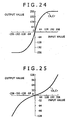
- the input-side LUT 19A is designed to have an input-output characteristic regarding color difference signals shown in Fig. 24 .
- the slope of the characteristic curve is steep near the achromatic axis and the slope becomes gentler as the degree of chroma increases.
- the input value that yields the convergence of the curve is optionally set on the high chroma side, and thus the range of a space to be processed by the subsequent 3D-LUT block 19 is controlled. If the range of the input value is larger than that of the output value, the input value is normalized with the range of the output value so that the processing accuracy is enhanced.
- the characteristic shown in Fig. 25 is the reverse characteristic of the characteristic shown in Fig. 24 , and is the input/output characteristic of the output-side LUT 19B regarding color difference signals.
- the input-side LUT 19A is designed to have an input/output characteristic shown in Fig. 26 , in which the slope of the characteristic curve is steep around important colors such as a skin color and in a high luminance area. This steep slope in a high luminance area is in order to enlarge the dynamic range.
- the characteristic shown in Fig. 27 is the reverse characteristic of the characteristic shown in Fig. 26 , and is the input/output characteristic of the output-side LUT 19B regarding a luminance signal.
- a color space is converted before and after processing by a LUT, and this color space conversion is executed through one-dimensional processing.
- an advantage of enhancing the accuracy of the processing by the 3D-LUT can be achieved in addition to advantages similar to those of the above-described embodiments. Specifically, fine color adjustment is carried out for achromatic colors and memory colors, for which the density of grid points is set to high, so that the accuracy of image quality correction can be enhanced.
- Fig. 28 is a block diagram illustrating, as a comparison with Fig. 23 , a 3D-LUT block applied to an electronic still camera according to a fifteenth embodiment of the invention together with related components.
- the electronic still camera according to the fifteenth embodiment has the same configuration as that of the electronic still camera of the fourteenth embodiment, except that configurations upstream and downstream of the 3D-LUT block are different.
- LUTs 19C and 19D for two-dimensional conversion processing as color space conversion, respectively, instead of the LUTs 19A and 19B for one-dimensional color space conversion.
- LUTs 19C and 19D correct color difference signals.
- offset units 19E to 19H are provided at the input and output stages of the 3D-LUT block 19 in the system of color difference signals.
- the color space of input image data is converted so that the density of grid points of the 3D-LUT block 19, regarding the hue, is set to high in an area requiring highly-accurate image quality correction. Accordingly, the accuracy of processing by the 3D-LUT block 19 is further enhanced compared with the fourteenth embodiment.
- one-dimensional color space conversion may be applied to a luminance signal.
- a color space is converted before and after processing by a LUT, and this color space conversion is executed through two-dimensional processing.
- An electronic still camera has a configuration obtained by replacing, in the configuration shown in Fig. 23 , the one-dimensional LUTs 19A and 19B by 3D-LUTs.
- a color space is converted before and after processing by a LUT, and this color space conversion is executed through three-dimensional processing.
- image data defined by primary color signals is to be processed.
- color space conversion from the RGB color space to the L*a*b* color space is executed.
- the reverse conversion of the conversion in the input-side LUT, or conversion from the L*a*b* color space to the YCC color space is executed. Therefore, correction data relating to the L*a*b* color space is set in a 3D-LUT block 19, and the 3D-LUT block 19 executes processing such as chroma correction.
- a color space is converted before and after processing by a LUT, and this color space conversion is executed through three-dimensional processing.
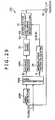
- Fig. 29 is a block diagram illustrating, as a comparison with Fig. 1 , a 3D-LUT block applied to an electronic still camera according to a seventeenth embodiment of the invention.
- the electronic still camera according to the seventeenth embodiment has the same configuration as that of any of the electronic still cameras of the first to sixteenth embodiments, except that this 3D-LUT block is applied.
- an area detector 109A determines the sampling values of input image data (Y2, Cb2, Cr2), and thus detects whether or not the sampling values of the input image data (Y2, Cb2, Cr2) exist in specific areas of plural areas set in the color space defined by the input image data (Y2, Cb2, Cr2).
- the specific areas correspond to areas requiring highly-accurate image quality correction, and include areas near memory colors such as a skin color and green.
- the area determiner 109B detects a reference grid point g1 and an offset p for the input image data (Y2, Cb2, Cr2) based on the determination as to the sampling values of the input image data. In this processing, the area determiner 109B detects and outputs the reference grid point g1 and the offset p only when the area detector 109A has detected the existence of the sampling values of the input image data (Y2, Cb2, Cr2) in the specific areas of the color space.
- the color space pertaining to correction data for the 3D-LUT 33 is divided according to the area segmentation by the area detector 109A, and only the correction data corresponding to the specific areas concerning the detection by the area detector 109A is recorded in the 3D-LUT 33. Since only the correction data corresponding to the specific areas is thus recorded, the recording of high resolution correction data is allowed correspondingly.
- the 3D-LUT block 109 produces a correction vector V and corrects the image quality of input image data only for the specific areas corresponding to memory colors. Therefore, the seventeenth embodiment allows further enhancement of the accuracy of image quality correction.
- the conversion parameters in the address decoder 109C as well as the correction data for the 3D-LUT 33 are switched depending on an image quality correction mode.
- assignment to a color space is switched on each image quality correction mode basis, which also further enhances the accuracy of image quality correction.
- the number of areas into which the color space of input image data is divided may be switched through the switching of areas detected by the area detector 109A.
- a color space relating to a 3D-LUT is divided into a plurality of areas, and processing by the 3D-LUT is switched on each area basis.
- adjustment accuracy for specific areas corresponding to memory colors and the like can be enhanced. Therefore, an advantage of more finely adjusting image quality can be achieved in addition to advantages similar to those of the above-described embodiments.
- Fig. 30 is a block diagram illustrating, as a comparison with Fig. 1 , the peripheral configuration of a 3D-LUT block applied to an electronic still camera according to an eighteenth embodiment of the invention.
- the electronic still camera according to the eighteenth embodiment has the same configuration as that of any of the electronic still cameras of the first to seventeenth embodiments, except that the peripheral configuration of a 3D-LUT block 19 is different.
- correction data for the 3D-LUT 33 produced by another imaging device such as a personal computer is obtained via a recording medium such as a memory card coupled to an external interface (I/F) 122, and is recorded in the memory 22.
- the correction data obtained via the external I/F 122 is set in the 3D-LUT 33 in response to operation by a user.
- the electronic still camera 1 can duplicate conditions of image quality correction made by another device.
- correction data recorded in the memory 22 is recorded in a recording medium via the external I/F 122 so that the correction data can be edited in a computer or the like and can be set in another imaging device.
- correction data by another imaging device is obtained via an external I/F and is set in a 3D-LUT, which allows the duplication of conditions of image quality correction made by the another device.
- An electronic still camera acquires an imaging result recorded by another imaging device via e.g. a memory card, and creates correction data to be set in a 3D-LUT from this imaging result. Therefore, this electronic still camera performs the emulation of image quality correction processing by another imaging device to thereby enhance usability for a user.
- the electronic still camera according to the nineteenth embodiment has the same configuration as that of any of the electronic still cameras of the first to seventeenth embodiments, except that a controller and the like for controlling the entire operation can execute processing for this emulation.
- the electronic still camera and another imaging device perform the imaging of the same color chart under the same imaging conditions, and then the controller in the electronic still camera executes the processing procedures of Figs. 9 and 10 with use of these two imaging results to thereby create correction data.
- the imaging result by another imaging device is set as the target colors of the respective grid points.
- this electronic still camera produces correction data for the 3D-LUT so that image quality correction implemented by another imaging device can be duplicated.
- an imaging result recorded by another imaging device is obtained and then correction data to be set in a 3D-LUT is creased, which allows emulation of image quality correction processing in this imaging device.
- correction data for a 3D-LUT is produced based on the YCC color space.
- correction data may be designed on the L*a*b* color space or the CIECAM02 Jab color space.
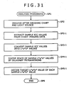
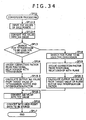
- Figs. 31 to 34 are flowcharts, as comparisons with Figs. 9 and 10 , showing processing procedures for creating correction data on the L*a*b* color space and the CIECAM02 Jab color space. In these processing procedures, sampling values are converted and processed according to the color space to be used for the creation of correction data as shown in the flowcharts, in which numerals of processing steps are associated with those of the corresponding steps in Figs. 9 and 10 .
- correction data can be created easily and surely similarly to the above-described embodiments.
- an imaging result as a still image is obtained by an electronic still camera.
- the present invention is not limited to the embodiments, but can also be widely applied to acquisition of an imaging result as a moving image by use of an electronic still camera or a video camera.
- the condition of image quality correction may be changed along the time axis by gradually changing weighting factors relating to a processing result by a 3D-LUT, which have been described above for the eights and ninth embodiments and so forth.
- an imaging result is processed in real time.
- An imaging result may be recorded in a recording medium as so-called RAW data, and later may be subjected to image quality adjustment employing processing corresponding to any of the above-described embodiments.
- RAW data imaging conditions that can be detected only at the time of obtaining an imaging result may also be recorded and held with the RAW data. Thereafter, the RAW data may be subjected to processing similar to that of any of the third and fourth embodiments.
- an imaging result of which image quality has been corrected is recorded in a recorded medium.
- the present invention is not limited to the embodiments.
- Information specifying the correction data used for the image quality correction may be recorded together with the corrected imaging result, and the information may be utilized for subsequent processing.
- the present invention is applied to an electronic still camera.
- the invention is not limited to the embodiments, but can also be widely applied to other various imaging devices such as video cameras and camera-equipped cellular phones.
Landscapes
- Engineering & Computer Science (AREA)
- Multimedia (AREA)
- Signal Processing (AREA)
- Image Processing (AREA)
- Facsimile Image Signal Circuits (AREA)
- Color Image Communication Systems (AREA)
- Color Television Image Signal Generators (AREA)
- Processing Of Color Television Signals (AREA)
Claims (19)
- Dispositif (1) de formation d'image comprenant :un élément de formation d'image (12) constitué pour sortir des données de formation d'image représentant une image optique formée sur un plan de formation d'image ;un objectif constitué pour former l'image optique sur le plan de formation d'image ;une mémoire mémorisant une table tridimensionnelle de consultation contenant des données de correction ;un processeur d'image (19) constitué pour mettre en oeuvre un ajustement de couleurs en ajoutant un vecteur de correction aux données de formation d'image dans un espace de couleurs, le vecteur de correction étant défini par des données de correction dans la table tridimensionnelle de consultation ; etun enregistreur (20) constitué pour enregistrer les données de formation d'image traitées par le processeur d'image (19) sur un support d'enregistrement,caractérisé en ce qu'il comprend en outre :un régisseur (21) constitué pour appliquer un facteur de pondération aux données de correction dans la table tridimensionnelle de consultation,dans lequel le régisseur (21) est constitué pour ajuster une qualité d'image des données de formation d'image en commandant le facteur de pondération.
- Dispositif (1) de formation d'image comprenant :un élément de formation d'image (12) constitué pour sortir des données de formation d'image représentant une image optique formée sur un plan de formation d'image ;un objectif constitué pour former l'image optique sur le plan de formation d'image ;un processeur d'image (19) constitué pour mettre en oeuvre un ajustement de couleurs en ajoutant un vecteur de correction aux données de formation d'image dans un espace de couleurs, le vecteur de correction étant défini par des données de correction dans la table tridimensionnelle de consultation ; etun enregistreur (20) constitué pour enregistrer les données de formation d'image traitées par le processeur d'image (19) sur un support d'enregistrement,caractérisé en ce qu'il comprend en outre :un régisseur (21) constitué pour ajuster une qualité d'image des données de formation d'image,dans lequel le processeur d'image (19) est constitué pour engendrer ledit vecteur de correction en multipliant un vecteur sorti de la table tridimensionnelle de consultation par un facteur de pondération, etdans lequel le régisseur (21) est constitué pour commander le facteur de pondération pour ajuster ainsi la qualité d'image des données de formation d'image.
- Dispositif (1) de formation d'image selon la revendication 2,
dans lequel :il est prévu une pluralité de tables tridimensionnelles de consultation ; etle processeur d'image (19) est constitué pour engendrer ledit vecteur de correction en synthétisant des vecteurs de sortie de la pluralité de tables tridimensionnelles de consultation, en multipliant chaque vecteur de sortie par un facteur de pondération, pour mettre ainsi en oeuvre l'ajustement de couleurs ; etle régisseur (21) est constitué pour commander les facteurs de pondération pour la synthèse des vecteurs de sortie pour ajuster ainsi la qualité d'image du résultat de formation d'image. - Dispositif (1) de formation d'image selon la revendication 1, 2 ou 3, comprenant en outre :une mémoire (22) constituée pour mémoriser une pluralité de sortes de données de correction à mettre dans la table tridimensionnelle de consultation ; etun régisseur (21) constitué pour choisir des données de correction à partir de la pluralité de sortes de données de correction mémorisée dans la mémoire (22), et pour mettre dans la table tridimensionnelle de consultation les données de correction choisies.
- Dispositif (1) de formation d'image selon la revendication 1, 2 ou 3, comprenant en outre :une mémoire (22) constituée pour mémoriser une pluralité de sortes de données de correction à mettre dans la table tridimensionnelle de consultation ; etun régisseur (21) constitué pour créer des données de correction par un traitement arithmétique d'interpolation avec l'utilisation de la pluralité de sortes de données de correction mémorisée dans la mémoire (22), et pour mettre dans la table tridimensionnelle de consultation les données de correction créées.
- Dispositif (1) de formation d'image selon la revendication 4, comprenant en outre :une unité d'affichage (2) constituée pour afficher les données de formation d'image,dans lequel le régisseur (21) est constitué pour faire que l'unité d'affichage (2) affiche un menu incluant une pluralité de sortes d'articles correspondant à la pluralité de sortes de données de correction, et accepte le choix d'un article par un utilisateur, etdans lequel le dispositif (1) est constitué de façon à mettre dans la table tridimensionnelle de consultation des données de correction qui correspondent à l'article choisi par l'utilisateur.
- Dispositif (1) de formation d'image selon la revendication 5, comprenant en outre :une unité d'affichage (2) constituée pour afficher les données de formation d'image,dans lequel le régisseur (21) est constitué pour faire que l'unité d'affichage (2) affiche un menu incluant une pluralité de sortes d'articles correspondant à la pluralité de sortes de données de correction, et accepte le choix d'un premier article et d'un deuxième article,dans lequel le régisseur (21) est constitué pour placer sur l'unité d'affichage (2) une fenêtre de paramétrage pour un ton intermédiaire des premier et deuxième articles choisis, et pour accepter le paramétrage d'un facteur de pondération pour le ton intermédiaire, etdans lequel le dispositif (1) est constitué de façon à mettre dans la table tridimensionnelle de consultation, en tant que données de correction créées, des données de correction produites par un traitement arithmétique d'interpolation avec l'utilisation du facteur de pondération et des données de correction correspondant au premier et deuxième articles.
- Dispositif (1) de formation d'image selon la revendication 4, dans lequel le régisseur est constitué pour choisir les données de correction à mettre dans la table tridimensionnelle de consultation (3D-LUT pour "Three- dimensional Look-Up Table") en fonction d'une condition de formation d'image qui peut être détectée au moment de l'acquisition des données de formation d'image par l'élément de formation d'image (12).
- Dispositif (1) de formation d'image selon la revendication 5, dans lequel le régisseur (21) est constitué pour paramétrer un facteur d'interpolation à utiliser pour le traitement arithmétique d'interpolation en fonction d'une condition de formation d'image qui peut être détectée au moment de l'acquisition des données de formation d'image par l'élément de formation d'image (12).
- Dispositif (1) de formation d'image selon la revendication 1, 2 ou 3, comprenant en outre :une unité d'affichage (2) constituée pour afficher les données de formation d'image,dans lequel le régisseur (21) est constitué pour faire que l'unité d'affichage (2) affiche une fenêtre de paramétrage, et accepte un paramétrage du facteur de pondération par une entrée faite au moyen de la fenêtre de paramétrage.
- Dispositif (1) de formation d'image selon la revendication 1, 2 ou 3, dans lequel le régisseur (21) est constitué pour paramétrer le facteur de pondération en fonction d'une condition de formation d'image qui peut être détectée seulement au moment de l'acquisition des données de formation d'image par l'élément de formation d'image (12).
- Dispositif (1) de formation d'image selon la revendication 1, 2 ou 3, dans lequel le processeur d'image (19) est constitué pour mettre en oeuvre une limitation, sans changement de teinte, pour les données de formation d'image qui vont au-delà d'une plage d'un espace de couleurs défini par le format d'enregistrement de l'enregistrement sur le support d'enregistrement, et pour sortir des données de formation d'image résultantes, la limitation dépendant du paramétrage des données de correction placées dans la table tridimensionnelle de consultation.
- Dispositif (1) de formation d'image selon la revendication 1, 2 ou 3, dans lequel la table tridimensionnelle de consultation est conçue de façon que les axes respectifs aient des définitions différentes.
- Dispositif (1) de formation d'image selon la revendication 1, 2 ou 3, dans lequel le processeur d'image (19) comprend :un convertisseur d'espace de couleurs de côté entrée constitué pour convertir un espace de couleurs des données de formation d'image provenant de l'élément de formation d'image (12), et pour sortir des données de formation d'image résultantes en tant que données à traiter par la table tridimensionnelle de consultation ; etun convertisseur d'espace de couleurs de côté sortie constitué pour convertir un espace de couleurs d'un résultat de traitement par la table tridimensionnelle de consultation avec une caractéristique inverse de la caractéristique du convertisseur d'espace de couleurs de côté entrée, et pour sortir un résultat de formation d'image résultant.
- Dispositif (1) de formation d'image selon la revendication 1, 2 ou 3,
dans lequel le processeur d'image (19) est constitué pour diviser un espace de couleurs des données de formation d'image provenant de l'élément de formation d'image (12) en une pluralité de zones, et pour déterminer à quelle zone appartiennent les données de formation d'image, et
dans lequel le processeur d'image (19) est constitué pour commuter l'accès à la table tridimensionnelle de consultation en fonction du résultat de détermination. - Dispositif (1) de formation d'image selon la revendication 1, 2 ou 3 comprenant en outre :un régisseur (21) constitué pour mettre des données de correction dans la table tridimensionnelle de consultation,dans lequel le régisseur (21) est constitué pour créer les données de correction en paramétrant des données de formation d'image obtenues par un autre dispositif de formation d'image en tant que valeur cible, et pour mettre dans la 3D-LUT les données de correction créées.
- Procédé de traitement d'un résultat de formation d'image dans un dispositif (1) de formation d'image, comprenant :la mise en oeuvre d'un ajustement de couleurs pour des données de formation d'image obtenues par un élément de formation d'image en ajoutant un vecteur de correction aux données de formation d'image dans un espace de couleurs, le vecteur de correction étant défini par des données de correction dans une table tridimensionnelle de consultation,et caractérisé en ce qu'il comprend en outre :l'application d'un facteur de pondération aux données de correction dans la table tridimensionnelle de consultation ; etl'ajustement de la qualité d'image des données de formation d'image en commandant le facteur de pondération.
- Procédé de traitement d'un résultat de formation d'image dans un dispositif (1) de formation d'image, comprenant :la mise en oeuvre d'un ajustement de couleurs pour des données de formation d'image obtenues par un élément de formation d'image en ajoutant un vecteur de correction aux données de formation d'image dans un espace de couleurs, le vecteur de correction étant défini par des données de correction dans une table tridimensionnelle de consultation,et caractérisé :en ce que ledit lecteur de correction est engendré en multipliant un vecteur sorti de la table tridimensionnelle de consultation par un facteur de pondération, etet en ce qu'il comprend en outre la commande du facteur de pondération pour ajuster ainsi la qualité d'image des données de formation d'image.
- Procédé selon la revendication 18, dans lequel :ledit vecteur de correction est engendré en synthétisant des vecteurs de sortie d'une pluralité de tables tridimensionnelles de consultation, chaque vecteur de sortie étant multiplié par un facteur de pondération, pour mettre ainsi en oeuvre l'ajustement de couleurs ; eten commandant les facteurs de pondération pour la synthèse des vecteurs de sortie pour ajuster ainsi la qualité d'image du résultat de formation d'image.
Applications Claiming Priority (1)
| Application Number | Priority Date | Filing Date | Title |
|---|---|---|---|
| JP2005160841A JP4304623B2 (ja) | 2005-06-01 | 2005-06-01 | 撮像装置及び撮像装置における撮像結果の処理方法 |
Publications (3)
| Publication Number | Publication Date |
|---|---|
| EP1729526A2 EP1729526A2 (fr) | 2006-12-06 |
| EP1729526A3 EP1729526A3 (fr) | 2007-03-21 |
| EP1729526B1 true EP1729526B1 (fr) | 2011-10-05 |
Family
ID=37005922
Family Applications (1)
| Application Number | Title | Priority Date | Filing Date |
|---|---|---|---|
| EP06252851A Active EP1729526B1 (fr) | 2005-06-01 | 2006-06-01 | Procédé et dispositif pour le réglage de la couleur par l'utilisation d'un tableau de consultation à trois dimensions |
Country Status (6)
| Country | Link |
|---|---|
| US (1) | US8223410B2 (fr) |
| EP (1) | EP1729526B1 (fr) |
| JP (1) | JP4304623B2 (fr) |
| KR (1) | KR101311925B1 (fr) |
| CN (6) | CN101282491B (fr) |
| TW (1) | TWI373261B (fr) |
Families Citing this family (56)
| Publication number | Priority date | Publication date | Assignee | Title |
|---|---|---|---|---|
| JP4273108B2 (ja) * | 2005-09-12 | 2009-06-03 | キヤノン株式会社 | 色処理方法、色処理装置及び記憶媒体 |
| US7864175B2 (en) * | 2006-03-09 | 2011-01-04 | Ambercore Software Inc | Fast gridding of irregular data |
| JP4290193B2 (ja) * | 2006-12-26 | 2009-07-01 | 三洋電機株式会社 | 画像処理装置 |
| US8422999B1 (en) * | 2007-08-06 | 2013-04-16 | Harris Technology, Llc | Portable camera enabled device applications |
| JP2009081812A (ja) * | 2007-09-27 | 2009-04-16 | Nec Electronics Corp | 信号処理装置および信号処理方法 |
| US7986434B2 (en) * | 2008-04-25 | 2011-07-26 | Kabushiki Kaisha Toshiba | System and method for color space transformation employing three dimensional linear interpolations |
| JP2010056794A (ja) * | 2008-08-27 | 2010-03-11 | Canon Inc | 多次色キャリブレーション用チャートと該チャートを使った画像処理方法及び画像処理装置 |
| JP5249077B2 (ja) * | 2009-02-17 | 2013-07-31 | キヤノン株式会社 | 撮像装置及び画像処理方法 |
| TWI399100B (zh) * | 2009-03-06 | 2013-06-11 | 勝華科技股份有限公司 | 影像處理方法 |
| JP5300595B2 (ja) | 2009-05-28 | 2013-09-25 | キヤノン株式会社 | 画像処理装置及び方法、及びコンピュータプログラム |
| CN101924949B (zh) * | 2009-06-12 | 2012-06-20 | 华硕电脑股份有限公司 | 影像处理方法与影像处理系统 |
| US8860751B2 (en) | 2009-09-01 | 2014-10-14 | Entertainment Experience Llc | Method for producing a color image and imaging device employing same |
| CN102598114B (zh) * | 2009-09-01 | 2015-09-16 | 娱乐体验有限责任公司 | 用于产生彩色图像的方法和使用该方法的成像设备 |
| US9110365B2 (en) * | 2009-11-19 | 2015-08-18 | Olympus Corporation | Imaging apparatus |
| JP2011124948A (ja) * | 2009-12-14 | 2011-06-23 | Sony Corp | 情報処理装置、情報処理方法、プログラム、及び光学顕微鏡を搭載した撮像装置 |
| US8928936B2 (en) * | 2009-12-21 | 2015-01-06 | Ricoh Production Print Solutions LLC | Red-green-blue to monochrome color conversion |
| JP5031877B2 (ja) * | 2010-01-06 | 2012-09-26 | キヤノン株式会社 | 画像処理装置及び画像処理方法 |
| JP2011188083A (ja) * | 2010-03-05 | 2011-09-22 | Sony Corp | 情報処理装置、情報処理方法、プログラム、及び光学顕微鏡を搭載した撮像装置 |
| KR101783259B1 (ko) * | 2010-12-31 | 2017-10-10 | 삼성디스플레이 주식회사 | 데이터 보상 방법 및 이를 수행하는 데이터 보상 장치 및 상기 데이터 보상 장치를 포함하는 표시 장치 |
| JP5887998B2 (ja) * | 2011-03-17 | 2016-03-16 | 株式会社リコー | 測色装置、記録装置、測色方法及びプログラム |
| CN103518221B (zh) | 2011-05-11 | 2017-03-08 | I<sup>3</sup>研究所股份有限公司 | 图像处理装置及方法、用计算机程序进行图像处理的方法 |
| US9160937B2 (en) * | 2011-08-30 | 2015-10-13 | Sharp Kabushika Kaisha | Signal processing apparatus and signal processing method, solid-state imaging apparatus, electronic information device, signal processing program, and computer readable storage medium |
| US8395666B1 (en) * | 2011-09-04 | 2013-03-12 | Videoq, Inc. | Automated measurement of video quality parameters |
| JP5889010B2 (ja) * | 2012-01-31 | 2016-03-22 | キヤノン株式会社 | 撮像装置およびその制御方法 |
| US20130235399A1 (en) * | 2012-03-09 | 2013-09-12 | Xerox Corporation | Systems and methods for employing declarative programming to optimize dynamic operations in complex image forming and media handling devices |
| TWI471848B (zh) * | 2012-03-27 | 2015-02-01 | Altek Corp | 顏色校正方法與影像處理裝置 |
| JP5880253B2 (ja) * | 2012-04-25 | 2016-03-08 | 富士ゼロックス株式会社 | 色処理装置及び色処理プログラム |
| JP2015007739A (ja) * | 2012-10-01 | 2015-01-15 | キヤノン株式会社 | 表示装置及びその制御方法 |
| US10577895B2 (en) | 2012-11-20 | 2020-03-03 | Drilling Info, Inc. | Energy deposit discovery system and method |
| US20140176743A1 (en) * | 2012-12-20 | 2014-06-26 | Thomson Licensing | Method, apparatus and system for publishing creative looks as three-dimensional lookup tables |
| US8780210B1 (en) * | 2013-02-01 | 2014-07-15 | Videoq, Inc. | Video quality analyzer |
| US10853893B2 (en) | 2013-04-17 | 2020-12-01 | Drilling Info, Inc. | System and method for automatically correlating geologic tops |
| US10459098B2 (en) | 2013-04-17 | 2019-10-29 | Drilling Info, Inc. | System and method for automatically correlating geologic tops |
| JP6399808B2 (ja) * | 2014-05-28 | 2018-10-03 | キヤノン株式会社 | 画像処理装置、画像処理方法、及びプログラム |
| WO2015192380A1 (fr) * | 2014-06-20 | 2015-12-23 | 深圳市尊正数字视频有限公司 | Dispositif de surveillance de retouche, système de retouche et procédé de retouche |
| CN104079928A (zh) * | 2014-07-07 | 2014-10-01 | 广东欧珀移动通信有限公司 | 摄像头的一致性校准方法、装置及移动设备 |
| US10171706B2 (en) * | 2014-10-30 | 2019-01-01 | Hewlett-Packard Development Company, L.P. | Configuring an imaging system |
| US9911210B1 (en) * | 2014-12-03 | 2018-03-06 | Drilling Info, Inc. | Raster log digitization system and method |
| JP6425264B2 (ja) * | 2015-02-26 | 2018-11-21 | Necディスプレイソリューションズ株式会社 | 色変換データ生成装置、色変換データ生成方法、及び表示装置 |
| US10908316B2 (en) | 2015-10-15 | 2021-02-02 | Drilling Info, Inc. | Raster log digitization system and method |
| CN106791756A (zh) * | 2017-01-17 | 2017-05-31 | 维沃移动通信有限公司 | 一种多媒体数据处理方法及移动终端 |
| JP7077698B2 (ja) | 2018-03-20 | 2022-05-31 | 株式会社Jvcケンウッド | 撮像装置、撮像方法及び撮像プログラム |
| CN109685859B (zh) * | 2018-12-24 | 2021-06-08 | 哈尔滨工业大学(深圳) | 基于3d查找表的三维颜色自动调整方法 |
| CN110400544A (zh) * | 2019-08-05 | 2019-11-01 | 业成科技(成都)有限公司 | 讯号处理方法及显示装置 |
| US11276246B2 (en) | 2019-10-02 | 2022-03-15 | Magic Leap, Inc. | Color space mapping for intuitive surface normal visualization |
| CN113470591B (zh) * | 2020-03-31 | 2023-11-14 | 京东方科技集团股份有限公司 | 监视器调色方法及装置、电子设备、存储介质 |
| JP7425361B2 (ja) * | 2020-04-27 | 2024-01-31 | 日本電信電話株式会社 | 画像調整装置、画像調整方法及びプログラム |
| CN115633250A (zh) * | 2021-07-31 | 2023-01-20 | 荣耀终端有限公司 | 一种图像处理方法及电子设备 |
| CN113810641B (zh) * | 2021-08-12 | 2023-02-28 | 荣耀终端有限公司 | 视频处理方法、装置、电子设备和存储介质 |
| CN115914600B (zh) * | 2021-09-30 | 2026-02-06 | 京东方科技集团股份有限公司 | 一种色彩校正方法、系统、显示设备及芯片 |
| CN116820367A (zh) * | 2022-03-21 | 2023-09-29 | 北京小米移动软件有限公司 | 图像显示方法、装置、电子设备及存储介质 |
| CN114913270B (zh) * | 2022-04-24 | 2025-06-10 | 杭州旷云金智科技有限公司 | 图像着色方法、电子设备、存储介质及计算机程序产品 |
| CN115083303B (zh) * | 2022-08-16 | 2022-11-08 | 成都索贝数码科技股份有限公司 | 移动视角下led显示屏空间色彩校正方法、介质及装置 |
| CN116546176B (zh) * | 2022-09-28 | 2025-11-14 | 腾讯科技(深圳)有限公司 | 一种色彩校正的方法、相关装置、设备以及存储介质 |
| TWI839893B (zh) * | 2022-10-14 | 2024-04-21 | 國立成功大學 | 場域影像遠端監控系統及魚塭影像遠端監控系統 |
| WO2024227268A1 (fr) * | 2023-05-01 | 2024-11-07 | Kunshan Yunyinggu Electronic Technology Co., Ltd. | Système et procédé d'étalonnage d'un panneau d'affichage |
Family Cites Families (32)
| Publication number | Priority date | Publication date | Assignee | Title |
|---|---|---|---|---|
| JPH0287192A (ja) | 1988-09-22 | 1990-03-28 | Konica Corp | 色分解画像修正方法及び装置 |
| US5428465A (en) * | 1991-08-12 | 1995-06-27 | Matsushita Electric Industrial Co., Ltd. | Method and apparatus for color conversion |
| DE4310727C2 (de) * | 1992-04-06 | 1996-07-11 | Hell Ag Linotype | Verfahren und Einrichtung zur Analyse von Bildvorlagen |
| JP3134660B2 (ja) | 1994-04-14 | 2001-02-13 | 松下電器産業株式会社 | 色変換方法および色変換装置 |
| EP0679020A1 (fr) * | 1994-04-19 | 1995-10-25 | Eastman Kodak Company | Procédé et appareil pour l'écrêtage limité de la gamme |
| US5668596A (en) * | 1996-02-29 | 1997-09-16 | Eastman Kodak Company | Digital imaging device optimized for color performance |
| JP3209402B2 (ja) | 1996-11-01 | 2001-09-17 | 富士ゼロックス株式会社 | 画像処理装置 |
| US7158144B2 (en) * | 1997-07-09 | 2007-01-02 | Canon Kabushiki Kaisha | Image processing apparatus and method for converting data dependent on a first illuminating light into data dependent on a second illuminating light |
| JP2001111858A (ja) | 1999-08-03 | 2001-04-20 | Fuji Photo Film Co Ltd | 色修正定義作成方法、色修正定義作成装置、および色修正定義作成プログラム記憶媒体 |
| JP4009812B2 (ja) * | 1999-08-18 | 2007-11-21 | 富士ゼロックス株式会社 | 画像処理装置、コンピュータ読取可能な記憶媒体、及び画像処理方法 |
| JP4210026B2 (ja) | 1999-09-30 | 2009-01-14 | セイコーエプソン株式会社 | 色修正装置、色修正方法および色修正制御プログラムを記録した記録媒体 |
| JP2001194238A (ja) | 2000-01-13 | 2001-07-19 | Dainippon Printing Co Ltd | 色変換テーブル作成方法および作成装置 |
| JP2002016818A (ja) | 2000-04-28 | 2002-01-18 | Fuji Photo Film Co Ltd | 色補正方法および装置並びに記録媒体 |
| JP3724339B2 (ja) * | 2000-06-15 | 2005-12-07 | セイコーエプソン株式会社 | 画像表示装置及びこれに用いられる色信号調整装置 |
| JP3561680B2 (ja) | 2000-07-14 | 2004-09-02 | 三洋電機株式会社 | ディジタルカメラ |
| DE60110399T2 (de) * | 2000-08-28 | 2006-01-19 | Seiko Epson Corp. | Sich an die umgebung anpassendes anzeigesystem, bildverarbeitungsverfahren und bildspeichermedium |
| JP5111702B2 (ja) | 2000-09-29 | 2013-01-09 | 大日本印刷株式会社 | Idカード作成システムにおける色補正方法及びidカード作成システム |
| JP2002204374A (ja) | 2000-10-23 | 2002-07-19 | Seiko Epson Corp | 色補正テーブル生成方法、画像処理装置、画像処理方法および記録媒体 |
| JP4250863B2 (ja) | 2000-11-08 | 2009-04-08 | ソニー株式会社 | 色補正処理方法および装置 |
| JP2002185804A (ja) | 2000-12-11 | 2002-06-28 | Ricoh Co Ltd | 色変換装置および色変換方法および色変換用パラメータ生成装置および色変換用パラメータ生成方法および画像処理システムおよび記録媒体 |
| JP2002344761A (ja) * | 2001-03-16 | 2002-11-29 | Seiko Epson Corp | 環境適応型の画像表示システム、プロジェクタ、プログラム、情報記憶媒体および画像処理方法 |
| JP3818098B2 (ja) | 2001-08-17 | 2006-09-06 | ソニー株式会社 | 画像信号処理方法及び画像信号処理装置 |
| JP2003219194A (ja) | 2002-01-28 | 2003-07-31 | Hitachi Ltd | 色補正装置および色補正方法 |
| JP2003244620A (ja) | 2002-02-19 | 2003-08-29 | Fuji Photo Film Co Ltd | 画像処理方法および装置並びにプログラム |
| US7289663B2 (en) * | 2002-07-24 | 2007-10-30 | Eastman Kodak Company | Producing an extended color gamut luminance-chrominance digital image from a captured image |
| JP3888456B2 (ja) | 2002-09-10 | 2007-03-07 | ソニー株式会社 | デジタルスチルカメラ |
| JP4040625B2 (ja) | 2002-09-12 | 2008-01-30 | 松下電器産業株式会社 | 画像処理装置、プリンタ装置、撮影装置、及びテレビ受像装置 |
| JP4217888B2 (ja) | 2003-08-08 | 2009-02-04 | 富士ゼロックス株式会社 | プロファイル変換装置およびプロファイル変換方法、色変換装置、色変換方法、画像形成装置、プロファイル変換処理プログラム、色変換処理プログラム、記憶媒体 |
| JP2005072850A (ja) | 2003-08-22 | 2005-03-17 | Noritsu Koki Co Ltd | 三次元lutの調整方法及び三次元lutを備えた色変換システム |
| US20070165048A1 (en) * | 2003-09-11 | 2007-07-19 | Matsushita Electric Industrial Co., Ltd. | Image processing device, image processing method, and image processing program |
| CN1279764C (zh) * | 2003-11-10 | 2006-10-11 | 华亚微电子(上海)有限公司 | 一种视频图像的色饱和度增强系统与方法 |
| JP2005160841A (ja) | 2003-12-04 | 2005-06-23 | Aruze Corp | 遊技機 |
-
2005
- 2005-06-01 JP JP2005160841A patent/JP4304623B2/ja not_active Expired - Lifetime
-
2006
- 2006-05-25 US US11/440,567 patent/US8223410B2/en active Active
- 2006-05-29 KR KR1020060048181A patent/KR101311925B1/ko active Active
- 2006-05-29 TW TW095119063A patent/TWI373261B/zh active
- 2006-06-01 CN CN2008100970163A patent/CN101282491B/zh active Active
- 2006-06-01 CN CN2008100970110A patent/CN101272507B/zh active Active
- 2006-06-01 CN CN2008100970125A patent/CN101272508B/zh active Active
- 2006-06-01 CN CN2006100837628A patent/CN1874410B/zh active Active
- 2006-06-01 CN CN2008100970093A patent/CN101272506B/zh active Active
- 2006-06-01 CN CN2008100970106A patent/CN101277453B/zh active Active
- 2006-06-01 EP EP06252851A patent/EP1729526B1/fr active Active
Also Published As
| Publication number | Publication date |
|---|---|
| JP4304623B2 (ja) | 2009-07-29 |
| CN1874410B (zh) | 2011-08-10 |
| CN101282491A (zh) | 2008-10-08 |
| JP2006339931A (ja) | 2006-12-14 |
| CN101272507A (zh) | 2008-09-24 |
| KR20060125493A (ko) | 2006-12-06 |
| EP1729526A2 (fr) | 2006-12-06 |
| US20060274386A1 (en) | 2006-12-07 |
| CN101277453B (zh) | 2010-06-23 |
| CN101277453A (zh) | 2008-10-01 |
| CN101272506B (zh) | 2011-07-06 |
| TWI373261B (en) | 2012-09-21 |
| CN101272508B (zh) | 2010-08-18 |
| KR101311925B1 (ko) | 2013-09-25 |
| CN101272506A (zh) | 2008-09-24 |
| CN101272507B (zh) | 2010-08-18 |
| CN101282491B (zh) | 2010-10-27 |
| CN101272508A (zh) | 2008-09-24 |
| TW200708076A (en) | 2007-02-16 |
| EP1729526A3 (fr) | 2007-03-21 |
| US8223410B2 (en) | 2012-07-17 |
| CN1874410A (zh) | 2006-12-06 |
Similar Documents
| Publication | Publication Date | Title |
|---|---|---|
| EP1729526A2 (fr) | Procédé et dispositif pour le réglage de la couleur par l'utilisation d'un tableau de consultation à trois dimensions | |
| EP1389003B1 (fr) | Procédé et appareil pour générer une table de conversion de couleurs | |
| JP4046647B2 (ja) | 色彩調整装置及びその方法 | |
| US7177465B1 (en) | Method of compressing/extending color reproducing space, color reproducing method and color reproducing apparatus | |
| US8265411B2 (en) | Image recording apparatus, image recording method, image processing apparatus, image processing method and image processing system | |
| KR20080030339A (ko) | 이 기종간 색역 사상 방법 및 장치 | |
| JP2005210526A (ja) | 画像処理装置、撮像装置、画像処理方法、画像データ出力方法、画像処理プログラム及び画像データ出力プログラム | |
| CN113810641B (zh) | 视频处理方法、装置、电子设备和存储介质 | |
| JP5027332B2 (ja) | ビデオスキントーン補正のための輪郭フリーポイント動作 | |
| US8687091B2 (en) | Image capturing systems and methods utilizing customizable look management | |
| WO2006059282A2 (fr) | Procede de traitement de saturation d'image couleur electronique | |
| JP4007964B2 (ja) | 画像処理装置、画像処理方法、及び画像処理プログラム | |
| JP2000134487A (ja) | 色変換装置 | |
| JP5024313B2 (ja) | 撮像装置及び撮像装置における撮像結果の処理方法 | |
| JP2005037996A (ja) | 画像処理装置および方法 | |
| JP4298730B2 (ja) | 色変換装置および方法 | |
| JP2007158446A (ja) | 画像処理装置、画像処理方法、プログラム、記憶媒体 | |
| JP2001313839A (ja) | 画像処理方法および装置並びに記録媒体 | |
| Son et al. | Color correction of projected image on color-screen for mobile beam-projector |
Legal Events
| Date | Code | Title | Description |
|---|---|---|---|
| PUAI | Public reference made under article 153(3) epc to a published international application that has entered the european phase |
Free format text: ORIGINAL CODE: 0009012 |
|
| AK | Designated contracting states |
Kind code of ref document: A2 Designated state(s): AT BE BG CH CY CZ DE DK EE ES FI FR GB GR HU IE IS IT LI LT LU LV MC NL PL PT RO SE SI SK TR |
|
| AX | Request for extension of the european patent |
Extension state: AL BA HR MK YU |
|
| PUAL | Search report despatched |
Free format text: ORIGINAL CODE: 0009013 |
|
| AK | Designated contracting states |
Kind code of ref document: A3 Designated state(s): AT BE BG CH CY CZ DE DK EE ES FI FR GB GR HU IE IS IT LI LT LU LV MC NL PL PT RO SE SI SK TR |
|
| AX | Request for extension of the european patent |
Extension state: AL BA HR MK YU |
|
| 17P | Request for examination filed |
Effective date: 20070823 |
|
| 17Q | First examination report despatched |
Effective date: 20070928 |
|
| AKX | Designation fees paid |
Designated state(s): DE FR GB |
|
| GRAJ | Information related to disapproval of communication of intention to grant by the applicant or resumption of examination proceedings by the epo deleted |
Free format text: ORIGINAL CODE: EPIDOSDIGR1 |
|
| GRAP | Despatch of communication of intention to grant a patent |
Free format text: ORIGINAL CODE: EPIDOSNIGR1 |
|
| GRAS | Grant fee paid |
Free format text: ORIGINAL CODE: EPIDOSNIGR3 |
|
| GRAA | (expected) grant |
Free format text: ORIGINAL CODE: 0009210 |
|
| AK | Designated contracting states |
Kind code of ref document: B1 Designated state(s): DE FR GB |
|
| REG | Reference to a national code |
Ref country code: GB Ref legal event code: FG4D |
|
| REG | Reference to a national code |
Ref country code: DE Ref legal event code: R081 Ref document number: 602006024842 Country of ref document: DE Owner name: HANGZHOU HIKVISION DIGITAL TECHNOLOGY CO., LTD, CN Free format text: FORMER OWNER: SONY CORPORATION, TOKIO/TOKYO, JP |
|
| REG | Reference to a national code |
Ref country code: DE Ref legal event code: R096 Ref document number: 602006024842 Country of ref document: DE Effective date: 20111215 |
|
| PLBE | No opposition filed within time limit |
Free format text: ORIGINAL CODE: 0009261 |
|
| STAA | Information on the status of an ep patent application or granted ep patent |
Free format text: STATUS: NO OPPOSITION FILED WITHIN TIME LIMIT |
|
| 26N | No opposition filed |
Effective date: 20120706 |
|
| REG | Reference to a national code |
Ref country code: DE Ref legal event code: R097 Ref document number: 602006024842 Country of ref document: DE Effective date: 20120706 |
|
| REG | Reference to a national code |
Ref country code: FR Ref legal event code: PLFP Year of fee payment: 10 |
|
| REG | Reference to a national code |
Ref country code: DE Ref legal event code: R082 Ref document number: 602006024842 Country of ref document: DE Representative=s name: MITSCHERLICH, PATENT- UND RECHTSANWAELTE PARTM, DE Ref country code: DE Ref legal event code: R081 Ref document number: 602006024842 Country of ref document: DE Owner name: HANGZHOU HIKVISION DIGITAL TECHNOLOGY CO., LTD, CN Free format text: FORMER OWNER: SONY CORPORATION, TOKIO/TOKYO, JP |
|
| REG | Reference to a national code |
Ref country code: FR Ref legal event code: TP Owner name: HANGZHOU HIKVISION DIGITAL TECHNOLOGY CO., LTD, CN Effective date: 20160105 |
|
| REG | Reference to a national code |
Ref country code: GB Ref legal event code: 732E Free format text: REGISTERED BETWEEN 20160218 AND 20160224 |
|
| REG | Reference to a national code |
Ref country code: FR Ref legal event code: PLFP Year of fee payment: 11 |
|
| REG | Reference to a national code |
Ref country code: FR Ref legal event code: PLFP Year of fee payment: 12 |
|
| REG | Reference to a national code |
Ref country code: FR Ref legal event code: PLFP Year of fee payment: 13 |
|
| P01 | Opt-out of the competence of the unified patent court (upc) registered |
Effective date: 20230424 |
|
| PGFP | Annual fee paid to national office [announced via postgrant information from national office to epo] |
Ref country code: DE Payment date: 20250617 Year of fee payment: 20 |
|
| PGFP | Annual fee paid to national office [announced via postgrant information from national office to epo] |
Ref country code: GB Payment date: 20250625 Year of fee payment: 20 |
|
| PGFP | Annual fee paid to national office [announced via postgrant information from national office to epo] |
Ref country code: FR Payment date: 20250630 Year of fee payment: 20 |