EP1729548A1 - Système de gestion pour commander l'intensité de la lumière comportant plusieurs unités de contrôle - Google Patents
Système de gestion pour commander l'intensité de la lumière comportant plusieurs unités de contrôle Download PDFInfo
- Publication number
- EP1729548A1 EP1729548A1 EP06006230A EP06006230A EP1729548A1 EP 1729548 A1 EP1729548 A1 EP 1729548A1 EP 06006230 A EP06006230 A EP 06006230A EP 06006230 A EP06006230 A EP 06006230A EP 1729548 A1 EP1729548 A1 EP 1729548A1
- Authority
- EP
- European Patent Office
- Prior art keywords
- arrangement according
- dimmer arrangement
- potentiometer
- bus system
- operating point
- Prior art date
- Legal status (The legal status is an assumption and is not a legal conclusion. Google has not performed a legal analysis and makes no representation as to the accuracy of the status listed.)
- Withdrawn
Links
Images

Classifications
-
- H—ELECTRICITY
- H05—ELECTRIC TECHNIQUES NOT OTHERWISE PROVIDED FOR
- H05B—ELECTRIC HEATING; ELECTRIC LIGHT SOURCES NOT OTHERWISE PROVIDED FOR; CIRCUIT ARRANGEMENTS FOR ELECTRIC LIGHT SOURCES, IN GENERAL
- H05B39/00—Circuit arrangements or apparatus for operating incandescent light sources
- H05B39/04—Controlling
- H05B39/08—Controlling by shifting phase of trigger voltage applied to gas-filled controlling tubes also in controlled semiconductor devices
- H05B39/083—Controlling by shifting phase of trigger voltage applied to gas-filled controlling tubes also in controlled semiconductor devices by the variation-rate of light intensity
- H05B39/085—Controlling by shifting phase of trigger voltage applied to gas-filled controlling tubes also in controlled semiconductor devices by the variation-rate of light intensity by touch control
- H05B39/086—Controlling by shifting phase of trigger voltage applied to gas-filled controlling tubes also in controlled semiconductor devices by the variation-rate of light intensity by touch control with possibility of remote control
-
- H—ELECTRICITY
- H05—ELECTRIC TECHNIQUES NOT OTHERWISE PROVIDED FOR
- H05B—ELECTRIC HEATING; ELECTRIC LIGHT SOURCES NOT OTHERWISE PROVIDED FOR; CIRCUIT ARRANGEMENTS FOR ELECTRIC LIGHT SOURCES, IN GENERAL
- H05B47/00—Circuit arrangements for operating light sources in general, i.e. where the type of light source is not relevant
- H05B47/10—Controlling the light source
- H05B47/17—Operational modes, e.g. switching from manual to automatic mode or prohibiting specific operations
-
- H—ELECTRICITY
- H05—ELECTRIC TECHNIQUES NOT OTHERWISE PROVIDED FOR
- H05B—ELECTRIC HEATING; ELECTRIC LIGHT SOURCES NOT OTHERWISE PROVIDED FOR; CIRCUIT ARRANGEMENTS FOR ELECTRIC LIGHT SOURCES, IN GENERAL
- H05B47/00—Circuit arrangements for operating light sources in general, i.e. where the type of light source is not relevant
- H05B47/10—Controlling the light source
- H05B47/165—Controlling the light source following a pre-assigned programmed sequence; Logic control [LC]
Definitions
- the invention is based on a designed according to the preamble of the main claim dimmer arrangement with multiple control points.
- Such dimmer arrangements with multiple keypads are designed to be able to turn on and off an assigned load or loads on the other hand via an operation of the associated actuator of each control point to be able to influence the degree of dimming of the associated loads as desired.
- By rotating the controls the user is able to set the desired brightness or dimming level of the connected loads intuitively.
- load or loads incandescent lamps, other bulbs, ballasts with bulbs and motorized shutters, blinds, fans can be changed in their degree of dimming.
- Phase control and phase control, 1-10V interfaces and digital control means are used as driving methods.
- incandescent lamps using a simple, end stops having rotary potentiometer in their brightness value or dimming adjusted continuously.
- dimmers are designed as a pressure changeover switch, which have a knob as an actuator, which must also be operated groping for switching on and off.
- Such dimmers are only capable of a limited extent of extension, so that it is not possible to influence the dimming level of the assigned loads of several control points on an equal basis, d.
- H. Although the associated lighting devices (loads) can be switched on and off in cross-exchange circuits of each control point, but a dimming operation can only be performed by a control point, namely the Hauptbedienstelle.
- the dimming speed is predetermined by the electronics, so that the user can not influence it.
- an intuitive adjustment of the dimming level or the brightness value of the connected loads is not possible in the above types of actuation because a fine motor actuation is to perform dimming and at the same time the desired degree of dimming on the load to be adjusted must be observed.
- the attention of the user is thus divided on the accurate operation of the control panel and the observation of the applied dimming of the lighting device, which is correspondingly cumbersome. For reasons of comfort, such operating modes are often undesirable.
- the present invention is therefore an object of the invention to provide a dimmer assembly with multiple control points, which allows a comparatively low cost of the potentiometer to be used a comfortable and intuitive operation of all control panels on an equal footing.
- z. B. a rotary actuator
- the dimming direction from bright to dark or vice versa is clearly specified and the dimming speed variable, namely intuitively determined by the operating speed of the user.
- at least one operating point is additionally groped actuated that z. B. on a short momentary actuation the switching on and off of the dimmer assembly is possible, and that by a long momentary actuation (greater than 10 seconds), the dimmer assembly in another operating condition, namely z. B. can be brought into a programming state.
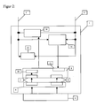
- such a dimmer arrangement consists essentially of a plurality of operating points 1, which are in each case connected via two connections 2 to a bus system 3, to which at least one load 4 to be influenced is connected.
- control or dimming is advantageously carried out by a rotary actuator at the control points 1.
- the actuators 5 of the control points 1 are designed for this reason as Tastwindknauf, so that an intuitive or self-explanatory operation is realized.
- An optical feedback by an optionally designed as a lighting device load 4 is given directly and uniquely for the user during the actuation process. Since the actuation process is performed intuitively by the user, even coarse motor actuations at the operating points 1 do not lead to incorrect operation.
- the user can determine the dimming speed of the connected load 4 in a simple manner by the operating speed he has specified.
- the speed of the change in brightness can thus be predetermined in a simple manner by the choice of the operating speed.
- the actuator 5 is designed as a Tastwindknauf, and the switching on and off of the dimmer assembly in a particularly simple, setbsterktDCde way is possible, because to turn on and off only a usual tactile operation on the actuator 5 is made.
- each control point 1 is essentially a simple, end stops exhibiting, designed as Tast- / Drehpotentiometer potentiometer 6 and an associated, designed as Tastwindknauf actuator 5 on.
- the potentiometer 6 or Tast- / Drehpotentiometer thus consists on the one hand of a variable by rotary actuation resistance and on the other hand influenced by Tastbetutz switch contacts.
- each operating point 1 is also provided with a first intended for the detection of rotary actuations Actuator detection device 7 and provided for the detection of Tastbetuschisten second actuation detection device 8 equipped.
- the actuation detection devices 7, 8 are provided to recognize the actuations on the actuator 5 and to deliver the positions tapped during the actuation process into the bus system 3 provided with the associated load 4.
- the tapped on the potentiometer 6 positions are delivered only from the actuating point 1 in the bus system 3, at the moment an actuating operation takes place or delivered only from the control panel 1 in the bus system 3, at the last an actuating operation of one of the two actuation detection devices 7, the eighth was determined.
- the delivery of the potentiometer 6 tapped positions takes place in the event of detection of the last occurred actuation process of the corresponding actuation point 1 cyclically repeated several times in the bus system 3.
- Both the first actuation detection device 7, and the second actuation detection device 8 each has a cooperating with the potentiometer 6 , in a microcontroller 9 of the keypad 1 deposited program part.
- the tapped at the potentiometers 6 positions are given by the control panels 1 as stored in the microcontroller 9 characteristics in the bus system 3, so that other bus subscribers, such. B. the load 4 can readily implement the tapped at the potentiometers 6 positions functionally.
- each operating point 1 has an evaluation unit 10 which detects the magnitude of an actuating process. If the actuation process is below a specific threshold value stored in the microcontroller 9, this is evaluated by the evaluation unit 10 as an interference signal, so that the positions tapped on the potentiometer 6 of the relevant control point 1 are not output to the bus system 3. Only when the evaluation unit 10 detects an actuation process at one of the control points 1, which is above the threshold value stored in the microcontroller 9, the positions tapped on the potentiometer 6 of the relevant control point 1 are output to the bus system 3 for functional fulfillment.
- each operating point 1 has an output unit 14, which outputs the positions of the potentiometer 6 stored as characteristic values as telegrams in the bus system 3.
- the load 4 is designed as a lighting device is determined by the position on the corresponding control point 1, the lighting device with the set on the control point 1 or tapped dimming value turned on. If, subsequently, a rotary actuation takes place on the actuating member 5 designed as a rotary knob, the dimming value or brightness value is adjusted correspondingly to the lighting device in accordance with the operating speed set by the user.
- the bus system 3 is designed as a so-called DALI bus. So that the operating points 1 can receive the information or telegrams delivered via the bus system 3, each operating point 1 has a monitoring level 11. Thus, it is possible that each control point 1 is also informed about the functional state of the load 4 assigned to it via the bus system 3. Moreover, it is thus possible, via a synchronization stage 12 of the various control points 1 with respect to the operating state on or off in a simple manner to establish a function synchronization. That is, when trained as Tastcardknauf actuator 5 has been placed in the operating position Off at one of the control points 1, which automatically applied to all other control points 1 also the function position Off. Conversely, this also means when trained as Tastcardknauf actuator 5 has been placed in one of the control points 1 in the operating position A, which automatically applied to all other control points 1 also the function position A.
- each control point 1 The power required for the function of the electronic components of each control point 1 is ensured by a connected to the bus system 3 DC / DC power supply 13.
- each control points 1 can be brought into a so-called programming mode.
- device parameters such as the basic brightness, basic speed, etc.
- device parameters can be reset when the programming mode has been called from the off state, ie when a longer tactile actuation (greater than 10 seconds) in the off state at a control point 1.
Landscapes
- Circuit Arrangement For Electric Light Sources In General (AREA)
Applications Claiming Priority (1)
| Application Number | Priority Date | Filing Date | Title |
|---|---|---|---|
| DE102005025477 | 2005-06-03 |
Publications (1)
| Publication Number | Publication Date |
|---|---|
| EP1729548A1 true EP1729548A1 (fr) | 2006-12-06 |
Family
ID=36972920
Family Applications (1)
| Application Number | Title | Priority Date | Filing Date |
|---|---|---|---|
| EP06006230A Withdrawn EP1729548A1 (fr) | 2005-06-03 | 2006-03-27 | Système de gestion pour commander l'intensité de la lumière comportant plusieurs unités de contrôle |
Country Status (1)
| Country | Link |
|---|---|
| EP (1) | EP1729548A1 (fr) |
Cited By (3)
| Publication number | Priority date | Publication date | Assignee | Title |
|---|---|---|---|---|
| EP2996011A1 (fr) * | 2014-09-09 | 2016-03-16 | Insta Elektro GmbH | Module électrique/électronique de commande |
| EP2637284A3 (fr) * | 2012-03-05 | 2016-09-14 | Insta Elektro GmbH | Module de commande électrique |
| CN110996466A (zh) * | 2019-12-28 | 2020-04-10 | 广州达森灯光股份有限公司 | 一种led灯具的调光方法 |
Citations (4)
| Publication number | Priority date | Publication date | Assignee | Title |
|---|---|---|---|---|
| US5463286A (en) * | 1991-08-09 | 1995-10-31 | Lutron Electronics, Co., Inc. | Wall mounted programmable modular control system |
| DE29817814U1 (de) | 1998-10-06 | 1999-01-07 | Insta Elektro GmbH & Co KG, 58511 Lüdenscheid | Elektrisches Installationssystem |
| DE19940273A1 (de) | 1999-08-26 | 2001-03-08 | Insta Elektro Gmbh & Co Kg | Helligkeitssteuerung von Beleuchtungseinrichtungen über Haupt- und Nebenstellen |
| US6400103B1 (en) * | 1999-03-11 | 2002-06-04 | Power Circuit Innovations, Inc. | Networkable power controller |
-
2006
- 2006-03-27 EP EP06006230A patent/EP1729548A1/fr not_active Withdrawn
Patent Citations (4)
| Publication number | Priority date | Publication date | Assignee | Title |
|---|---|---|---|---|
| US5463286A (en) * | 1991-08-09 | 1995-10-31 | Lutron Electronics, Co., Inc. | Wall mounted programmable modular control system |
| DE29817814U1 (de) | 1998-10-06 | 1999-01-07 | Insta Elektro GmbH & Co KG, 58511 Lüdenscheid | Elektrisches Installationssystem |
| US6400103B1 (en) * | 1999-03-11 | 2002-06-04 | Power Circuit Innovations, Inc. | Networkable power controller |
| DE19940273A1 (de) | 1999-08-26 | 2001-03-08 | Insta Elektro Gmbh & Co Kg | Helligkeitssteuerung von Beleuchtungseinrichtungen über Haupt- und Nebenstellen |
Cited By (3)
| Publication number | Priority date | Publication date | Assignee | Title |
|---|---|---|---|---|
| EP2637284A3 (fr) * | 2012-03-05 | 2016-09-14 | Insta Elektro GmbH | Module de commande électrique |
| EP2996011A1 (fr) * | 2014-09-09 | 2016-03-16 | Insta Elektro GmbH | Module électrique/électronique de commande |
| CN110996466A (zh) * | 2019-12-28 | 2020-04-10 | 广州达森灯光股份有限公司 | 一种led灯具的调光方法 |
Similar Documents
| Publication | Publication Date | Title |
|---|---|---|
| DE19645907B4 (de) | Verfahren und Vorrichtung zum Einstellen eines Betriebszustandes eines Geräts, insbesondere eines Haushaltsgeräts | |
| DE19940273B4 (de) | Helligkeitssteuerung von Beleuchtungseinrichtungen über Haupt- und Nebenstellen | |
| DE4312615B4 (de) | Steuereinrichtung zur Erzeugung eines variablen Ausgangssignals | |
| DE19728538A1 (de) | Dimmer | |
| EP1729548A1 (fr) | Système de gestion pour commander l'intensité de la lumière comportant plusieurs unités de contrôle | |
| DE19917091C1 (de) | Vorrichtung zur Einstellung der Helligkeit eines Leuchtmittels, bei welcher durch den Benutzer wählbar sowohl sprunghaftes als auch stetiges Dimmen möglich ist | |
| EP2335459B1 (fr) | Circuit et procédé pour faire varier la lumière émise par un élément luminescent | |
| EP1659834B1 (fr) | Gradateur | |
| WO2011076387A2 (fr) | Système d'installation électrique | |
| DE202006004692U1 (de) | Dimmeranordnung mit mehreren Bedienstellen | |
| EP1425770B1 (fr) | Dispositif de réglage et de commande pour appareils électriques | |
| EP2400618A2 (fr) | Actionneur et système de gestion d'énergie doté de tels actionneurs | |
| EP3964033A1 (fr) | Procédé pour faire fonctionner un variateur | |
| DE102006033765B3 (de) | Dimmersystem mit mehreren Multidimmern und Multidimmer, welcher universell als Masterdimmer, als Slavedimmer oder als Nebenstelle einsetzbar ist | |
| DE102006062751B4 (de) | Multidimmer, welcher universell als Masterdimmer, als Slavedimmer oder als Nebenstelle einsetzbar ist | |
| WO2008012063A1 (fr) | Unité de commande multifonctionnelle pour un véhicule automobile | |
| DE102012101808B3 (de) | Elektrisches Steuermodul | |
| DE102007022345A1 (de) | Helligkeitssteuerung einer Beleuchtungseinrichtung mit einem Dimmer | |
| DE2618140C2 (de) | Anordnung zum Schalten und zur Leistungssteuerung von elektrischen Verbrauchern, insb. Glühlampen | |
| DE29914873U1 (de) | Helligkeitssteuerung von Beleuchtungseinrichtungen über Haupt- und Nebenstellen | |
| EP3934387B1 (fr) | Dispositif à connexion multifonctionnelle pour appareils de commande non dali | |
| EP1811623B1 (fr) | Appareil d'installation électrique/électronique | |
| EP2996011B1 (fr) | Module électrique/électronique de commande | |
| EP2892305A1 (fr) | Variateur | |
| EP2925096A2 (fr) | Procédé de commande d'une charge électrique ou d'un dispositif d'éclairage |
Legal Events
| Date | Code | Title | Description |
|---|---|---|---|
| PUAI | Public reference made under article 153(3) epc to a published international application that has entered the european phase |
Free format text: ORIGINAL CODE: 0009012 |
|
| AK | Designated contracting states |
Kind code of ref document: A1 Designated state(s): AT BE BG CH CY CZ DE DK EE ES FI FR GB GR HU IE IS IT LI LT LU LV MC NL PL PT RO SE SI SK TR |
|
| AX | Request for extension of the european patent |
Extension state: AL BA HR MK YU |
|
| AKX | Designation fees paid | ||
| STAA | Information on the status of an ep patent application or granted ep patent |
Free format text: STATUS: THE APPLICATION IS DEEMED TO BE WITHDRAWN |
|
| 18D | Application deemed to be withdrawn |
Effective date: 20070607 |
|
| REG | Reference to a national code |
Ref country code: DE Ref legal event code: 8566 |