EP1729567B1 - Leistungsaquariumsreinigungs- und -kiesvakuum - Google Patents
Leistungsaquariumsreinigungs- und -kiesvakuum Download PDFInfo
- Publication number
- EP1729567B1 EP1729567B1 EP05714120A EP05714120A EP1729567B1 EP 1729567 B1 EP1729567 B1 EP 1729567B1 EP 05714120 A EP05714120 A EP 05714120A EP 05714120 A EP05714120 A EP 05714120A EP 1729567 B1 EP1729567 B1 EP 1729567B1
- Authority
- EP
- European Patent Office
- Prior art keywords
- gravel
- filter
- suction
- pump
- assembly
- Prior art date
- Legal status (The legal status is an assumption and is not a legal conclusion. Google has not performed a legal analysis and makes no representation as to the accuracy of the status listed.)
- Expired - Lifetime
Links
- 238000004140 cleaning Methods 0.000 title description 47
- 241000251468 Actinopterygii Species 0.000 claims abstract description 42
- XLYOFNOQVPJJNP-UHFFFAOYSA-N water Substances O XLYOFNOQVPJJNP-UHFFFAOYSA-N 0.000 claims abstract description 36
- 238000000034 method Methods 0.000 claims abstract description 17
- 238000011045 prefiltration Methods 0.000 claims description 30
- 239000002699 waste material Substances 0.000 claims description 10
- OKTJSMMVPCPJKN-UHFFFAOYSA-N Carbon Chemical compound [C] OKTJSMMVPCPJKN-UHFFFAOYSA-N 0.000 claims description 7
- 229910052799 carbon Inorganic materials 0.000 claims description 7
- 230000037452 priming Effects 0.000 claims description 3
- 238000001784 detoxification Methods 0.000 claims description 2
- 230000007423 decrease Effects 0.000 claims 1
- 239000011806 microball Substances 0.000 description 16
- 230000008901 benefit Effects 0.000 description 10
- 239000011805 ball Substances 0.000 description 8
- 238000012423 maintenance Methods 0.000 description 8
- 230000000712 assembly Effects 0.000 description 6
- 238000000429 assembly Methods 0.000 description 6
- 230000008878 coupling Effects 0.000 description 6
- 238000010168 coupling process Methods 0.000 description 6
- 238000005859 coupling reaction Methods 0.000 description 6
- 125000000391 vinyl group Chemical group [H]C([*])=C([H])[H] 0.000 description 4
- 229920002554 vinyl polymer Polymers 0.000 description 4
- 241000894006 Bacteria Species 0.000 description 3
- 230000008859 change Effects 0.000 description 2
- 239000013505 freshwater Substances 0.000 description 2
- 230000006872 improvement Effects 0.000 description 2
- 239000000463 material Substances 0.000 description 2
- 238000005259 measurement Methods 0.000 description 2
- 239000002245 particle Substances 0.000 description 2
- 239000003053 toxin Substances 0.000 description 2
- 231100000765 toxin Toxicity 0.000 description 2
- 108700012359 toxins Proteins 0.000 description 2
- 239000004743 Polypropylene Substances 0.000 description 1
- 239000003610 charcoal Substances 0.000 description 1
- 239000000839 emulsion Substances 0.000 description 1
- 239000002991 molded plastic Substances 0.000 description 1
- 230000008635 plant growth Effects 0.000 description 1
- -1 polypropylene Polymers 0.000 description 1
- 229920001155 polypropylene Polymers 0.000 description 1
- 230000008569 process Effects 0.000 description 1
- 239000000126 substance Substances 0.000 description 1
Images


Classifications
-
- A—HUMAN NECESSITIES
- A01—AGRICULTURE; FORESTRY; ANIMAL HUSBANDRY; HUNTING; TRAPPING; FISHING
- A01K—ANIMAL HUSBANDRY; AVICULTURE; APICULTURE; PISCICULTURE; FISHING; REARING OR BREEDING ANIMALS, NOT OTHERWISE PROVIDED FOR; NEW BREEDS OF ANIMALS
- A01K63/00—Receptacles for live fish, e.g. aquaria; Terraria
- A01K63/04—Arrangements for treating water specially adapted to receptacles for live fish
- A01K63/045—Filters for aquaria
-
- A—HUMAN NECESSITIES
- A01—AGRICULTURE; FORESTRY; ANIMAL HUSBANDRY; HUNTING; TRAPPING; FISHING
- A01K—ANIMAL HUSBANDRY; AVICULTURE; APICULTURE; PISCICULTURE; FISHING; REARING OR BREEDING ANIMALS, NOT OTHERWISE PROVIDED FOR; NEW BREEDS OF ANIMALS
- A01K63/00—Receptacles for live fish, e.g. aquaria; Terraria
- A01K63/10—Cleaning bottoms or walls of ponds or receptacles
Definitions
- This invention relates to the maintenance of fish aquariums, specifically in the cleaning of the gravel and removal of fish waste, food debris and unwanted toxins.
- the drain assembly also allows for a garden hose adapter to be added so that the consumer can easily drain saltwater into the toilet or can water their garden in freshwater applications, as fish emulsion is a known plant growth stimulant. (to be offered in an accessory package).
- the power aquarium cleaning/gravel vacuum if used properly every month, will provide a safe and effective solution for aquarium maintenance by the consumer and will result in a much more stable and healthier environment for the fish.
- the power aquarium cleaning/gravel vacuum according to claim 1 is designed to service both saltwater and freshwater fish aquariums, that does not only clean and detoxify aquarium water and removes fish waste/food debris, but the machine actually allows the consumer to vacuum gravel down to #1 gravel size.
- the machine moves dirty water through an intake assembly, into the main unit and returns clean water through the return assembly back into the fish aquarium.
- the water passes through the main machine unit, travels through a pre-filter trap for gravel, a minimum twenty (20) micron filter for trapping fish waste/food debris, and a charcoal filter for removal of unwanted toxins.
- the unit has a micron ball valve for adjusting the flow rate for different size/shape aquariums and allowing for continued flow as the pre-filter and minimum twenty (20) micron filter begin to saturate.
- the unit allows the user to clean the aquarium as long as necessary while not removing bacteria essential for aquarium life. After the service the consumer may then remove twenty percent (20%) of the water minimum and replace it with the same amount of treated water. The power aquarium cleaning/gravel vacuum can then be drained and stored until the next needed service of the fish aquarium.
- a product according to a preferred embodiment is so unique that it will help to revitalize the aquarium industry, create new sales of fish aquariums/products for the aquarium/pet stores, and make cleaning and maintaining fish aquariums for the consumer much easier, safer, and a happier experience.
- Suction Tube 15 Strainer (Base Suck Tube) 16 Suction Tube (Base Suck Tube) 17 Housing Valve Pad (Suck Pump) 18 Valve Pad (Suck Pump) 19 Suction Pump (Suck Pump) 20 Cap Connector (Cap Coupling) 21 Barb Connector (Male Coupling) 22 Housing Connector (Female Coupling) 24 Ball Valve (Coupling) 26 Drain Cap 28 Pre-Filter Tower 30 Pre-Filter Trap 32 Cap - Top (Pre-Filter Trap) 34 Tower Cap 36 Bleeder Valve 38 Housing - Impeller 40 Nut - Impeller 42 Impeller 44 Housing - Pump.
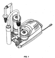
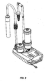
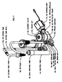
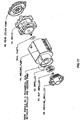
- FIG. 1 A preferred embodiment of the complete power aquarium cleaning / gravel vacuum is illustrated in Fig: 1 (angled front view), Fig. 2 (angled side view, Fig. 3 (angled rear view), and Fig. 4 (angled bottom view) Please note the drastic change in appearance of the preferred embodiment versus the embodiment of the original concept.
- the original embodiment is a functional but rather plain design.
- the preferred embodiment looks much more state of the art and encompasses many more features, as well as, making the power aquarium cleaning / gravel vacuum much easier for use by the consumer.
- the invention is not limited to this embodiment.
- FIG. 5 illustrates the overall height and length measurements from a side view.
- Fig. 6 illustrates the overall width measurements from a top view. While these illustrations show the preferred dimensions, the design of the complete power aquarium cleaning / gravel vacuum allows for various size and shape of the unit (machine), due to different accessory packages to be offered. The invention is not limited to these dimensions.
- FIG. 7 through 12 A preferred embodiment of the present complete power aquarium cleaning / gravel vacuum is illustrated in figures 7 through 12 .
- the majority of all components are molded plastic, such as polypropylene, unless otherwise specified in the aforementioned detailed description or operations to follow of the power aquarium cleaning / gravel vacuum. Other materials can be used.
- a suction tube 14 is press fit into a suction base 16 which houses a strainer .
- the suction base is connected to the suction pump 19 ( Fig. 8 , 10 ) by a length of ribbed flexible vinyl tubing (shown in Figs. 7 & 8 but not labeled). Ribbed flexible vinyl tubing is a common in the aquarium industry and, as such, is not listed in the reference numerals.
- the suction pump is comprised of a valve housing pad 17 ( Fig. 10 ) and a valve pad 18 ( Fig. 10 ). The valve housing and pad are press fit in each end of the suction pump.
- the ribbed tubing is press fit to the suction base and to both ends of the suction pump in order to seal the components
- the suction pump is connected to a coupling barb connector 21 ( Fig. 7 ) by a length of ribbed flexible vinyl tubing.
- the ribbed tubing is press fit to the coupling barb connector.
- a cap connector 20 secures the ribbed tubing to a housing connector 22 (female connector) by sliding over the ribbed tubing and screwing the cap connector down tight to the housing connector.
- a ball valve 24 which is inserted into the housing connector and secured by means of a rubber gasket and locking system.
- the housing connector is press fit, by means of a rubber gasket and locking system to a pre-filter tower 28 ( Fig. 7 ).
- a drain cap 26 is screwed on to the pre-filter tower and tightened down by means of a rubber gasket.
- the pre-filter tower houses a pre-filter trap 30 and pre-filter trap cap (top) 32.
- the pre-filter trap and top are secured inside the pre-filter tower by means of a tower cap 34.
- a bleeder valve 36 is screwed into the tower cap and secured by means of a rubber gasket.
- An impeller housing 38 ( Figs. 7 , 11 ) is press fit to the pre-filter tower by means of a rubber gasket.
- An impeller 42 is enclosed in the impeller housing and attached to a pump (motor) 46 by means of a nut 40.
- the motor is enclosed a pump housing 44 and sealed from the main flow of water by means of a shaft seal.
- the motor is enclosed to the pump housing by means of a rear cover 48 ( Fig.8 , 11 ).
- the complete motor assembly is fastened together with long screws and washers.
- the motor is attached to a power cord (not listed in the reference numerals) that exits through the rear cover.
- the pump housing is connected to the main tower 62 ( Figs. 8 , 12 ) by a L-tube 50.
- the L-tube is press fit to both the pump housing and the main filter by means of a rubber gasket.
- a micro ball valve housing 54 ( Figs. 8 , 12 ) is press fit to both the pre-filter tower and main tower by means of rubber gasket.
- a micro ball valve 52 ( Fig. 12 ) is inserted into the micro ball valve housing.
- a cap 56 screws down over the micro ball valve and secures it to the micro ball valve housing by means of a rubber gasket.
- a handle 58 is secured to the micro ball by means of a screw.
- a cap (cover) 60 is snapped over the handle.
- the main filter tower houses a carbon container 64 ( Fig. 8 ) and carbon container cap (top) 66.
- An extension tower cap 68 is screwed down to the main filter tower and sealed by means of a rubber gasket.
- An extension tower 70 is then snapped down into the extension cap and sealed by means of a rubber gasket.
- the extension tower houses a filter cartridge 72 and filter cartridge cap (top) 74.
- the extension tower is then sealed by means of another tower cap 34 and bleeder valve 36 ( Fig.7 ).
- Another housing connector assembly 21 though 26 is connected to the other end of the main filter tower.
- the assembly is attached to a return tube (rear) 76 by means of a length of ribbed flexible vinyl tubing that is press fit to the return tube (rear).
- the return tube (rear) is connected to a return tube (front) 80 by means of an adjustable return tube connector (cap) 78.
- the return tube connector slips over the return tube (front).
- the return tube (front) then slides into the return tube (rear) and the return tube connector (cap) screws down to the return tube (rear).
- a diffuser 82 is then press fit into the end of the return tube (front).
- housing (top) 84 and housing (bottom) 86 The preferred embodiment of the power aquarium cleaning / gravel vacuum is then enclosed in housing (top) 84 and housing (bottom) 86. This completes the detailed description of the total embodiment of the power aquarium cleaning / gravel vacuum.
- the power aquarium cleaning / gravel vacuum is a unique machine that has many benefits over previous ways of doing the required monthly maintenance of a fish aquarium.
- the manner that the consumer uses the machine is to first immerse the suction tube/suction base assembly 14, 15, 16 ( Fig. 7 ) into one end of the aquarium that the consumer desires to clean.
- the preferred embodiment of the complete power aquarium cleaning / gravel vacuum will be located below said aquarium and on the floor.
- the return assembly 76, 78, 80, 82 ( Fig. 7 ) should be placed and secured at the other end of said aquarium.
- the consumer will then open all micro ball valve assemblies 24, 52 though 60 ( Fig. 7 , 8 ) and the bleeder valves 36 ( Fig. 7 ) on the main filter tower.
- the bleeder valve on the pre-filter tower is to be closed. The consumer should make sure that all connections are hand tight and proceed to step two.
- the bleeder valve on the main filter tower will begin to hiss air out as the water flows through pre-filter assembly 29 through 36 ( Fig.7 ), the pump (motor) assembly 38 through 50 ( Figs. 7 , 8 ), the micro valve assembly 52 through 60 ( Fig. 8 ), and the main filter tower assembly 62 through 74.
- the bleeder valve on the main tower assembly will begin to spill water out.
- the consumer can begin to close the micro valve assembly 52 through 60.
- the water will begin to pull from the suction assembly through the main unit and back through the return assembly 76 through 82 ( Fig. 7 ).
- the consumer will then put the suction tube assembly into the gravel and adjust the micro valve assembly 52 through 60 until the gravel comes up into the suction tube approximately one quarter of the full length of the suction tube.
- the consumer can pull out and re-insert the tube into different parts of the aquarium to clean different sections of the gravel.
- the gravel can be cleaned while still in the aquarium.
- the consumer can now clean / gravel vacuum the aquarium, as necessary, until the fish waste and food debris are properly removed.
- the dirty water will travel through the machine, be filtered and detoxified, and return to the aquarium clean water. After use, turn off and unplug the unit.
- the invention can be used in different ways than those discussed above and is not limited to these operational details.
Landscapes
- Life Sciences & Earth Sciences (AREA)
- Environmental Sciences (AREA)
- Marine Sciences & Fisheries (AREA)
- Animal Husbandry (AREA)
- Biodiversity & Conservation Biology (AREA)
- Farming Of Fish And Shellfish (AREA)
- Preparation Of Clay, And Manufacture Of Mixtures Containing Clay Or Cement (AREA)
- Cleaning In General (AREA)
- Telephone Function (AREA)
- Diaphragms For Electromechanical Transducers (AREA)
Claims (21)
- Kiessauger, umfassend:eine Pumpe (46);eine abnehmbare, mit der Pumpe verbundene Saugbasis (16), an der ein Saugrohr (14) angebracht werden kann;einen mit der Saugbasis verbundenen Filter (62);eine Rücklaufanordnung (76, 78, 80);mindestens ein Ventil (52, 54); undeinen Ausweichströmungspfad;wobei
die Pumpe (46) einen Wasserstrom von der Saugbasis durch den Filter und aus der Rücklaufanordnung heraus antreibt;
das Ventil (54) ein Einstellen des Volumens des Stroms für verschiedene Größen von Fischaquarien erlaubt; und
der Ausweichströmungspfad auf die Pumpe rückwirkenden Druck reduziert, wenn das Ventil benutzt wird, um das Volumen des Stroms einzustellen. - Kiessauger nach Anspruch 1, weiter umfassend das an der Saugbasis angebrachte Saugrohr (14), wobei das Saugrohr einen ausreichenden Durchmesser aufweist, damit Kies hineinpasst.
- Kiessauger nach Anspruch 2, wobei verschieden lange Saugrohre an der Saugbasis angebracht werden können.
- Kiessauger nach Anspruch 1, weiter umfassend einen Abscheider in der Saugbasis.
- Kiessauger nach Anspruch 1, weiter umfassend eine quetschbare Saugpumpe, mit der der Reiniger vorbereitet werden kann.
- Kiessauger nach Anspruch 1, weiter umfassend eine Vorfilteranordnung, durch die das Wasser vor dem Filter hindurch fließt.
- Kiessauger nach Anspruch 6, wobei die Vorfilteranordnung eine mittels eines männlich/weiblich-Trennsystems verbundene Einlassanordnung umfasst.
- Kiessauger nach Anspruch 7, weiter umfassend ein Abschaltventil (24), welches die Wahrscheinlichkeit, dass Wasser während des Trennens der Einlassanordnung von der Vorfilteranordnung ausläuft, verringert.
- Kiessauger nach Anspruch 7, weiter umfassend eine Ablassanordnung zwischen der Einlassanordnung und der Vorfilteranordnung.
- Kiessauger nach Anspruch 1, weiter umfassend eine Kiesfalle, welche einen Motor in der Pumpe schützt.
- Kiessauger nach Anspruch 1, weiter umfassend einen Vorfilter für den Filter und eine Kiesfalle, welche den Vorfilter schützt.
- Kiessauger nach Anspruch 1, wobei der Filter einen Kohlenstoffbehälter zur Entgiftung des Wassers und einen Minimum-zwanzig (20)-Mikrometer-Filter zum Entfernen von Fischabfall und Futterablagerungen aus dem Wasser umfasst.
- Kiessauger nach Anspruch 1, weiter umfassend ein Abschaltventil zum Assistieren, wenn die Rücklaufanordnung von dem Filterturm getrennt wird.
- Kiessauger nach Anspruch 1, wobei die Rücklaufanordnung einstellbar ist und ein Rücklaufrohr und einen Diffusor umfasst.
- Verfahren zum Benutzen eines Kiessaugers,
wobei der Kiessauger eine Pumpe (46), eine abnehmbare, mit der Pumpe verbundene Saugbasis (16), an der ein Saugrohr (14) angebracht werden kann, einen mit dem Saugrohr (16) verbundenen Filter (62), eine Rücklaufanordnung, mindestens ein Ventil (52, 54) und einen Ausweichströmungspfad umfasst, wobei die Pumpe einen Wasserstrom von der Saugbasis durch den Filter und aus der Rücklaufanordnung heraus antreibt,
wobei das Verfahren die Schritte umfasst:Anbringen eines Saugrohrs an der Saugbasis;Eintauchen des Saugrohrs in ein Aquarium;Einschalten der Pumpe;Einführen des Saugrohrs in den Kies; undBenutzen des Ventils zum Einstellen des Volumens des Stroms für verschiedene Größen von Fischaquarien;wobei der Ausweichströmungspfad auf die Pumpe rückwirkenden Druck reduziert, wenn das Ventil benutzt wird, um das Volumen des Stroms einzustellen;
wodurch der Kies in dem Saugrohr gereinigt wird, während er noch im Aquarium ist. - Verfahren nach Anspruch 15, wobei der Kiessauger weiter das Saugrohr umfasst, und wobei das Verfahren weiter das Anbringen des Saugrohrs an der Saugbasis umfasst, wobei das Saugrohr einen ausreichenden Durchmesser aufweist, damit Kies hineinpasst.
- Verfahren nach Anspruch 15, wobei verschieden lange Saugrohre an der Saugbasis angebracht werden können.
- Verfahren nach Anspruch 15, wobei der Kiessauger weiter einen Abscheider in der Saugbasis umfasst.
- Verfahren nach Anspruch 15, wobei der Kiessauger weiter eine quetschbare Saugpumpe umfasst, und wobei das Verfahren weiter das Vorbereiten des Reinigers mit der quetschbaren Pumpe umfasst.
- Verfahren nach Anspruch 15, wobei der Kiessauger weiter ein Abschaltventil umfasst, und
wobei das Verfahren weiter das Benutzen des Abschaltventils zum Assistieren, wenn die Rücklaufanordnung von dem Filterturm getrennt wird, umfasst. - Verfahren nach Anspruch 15, wobei die Rücklaufanordnung einstellbar ist und weiter ein Rücklaufrohr und einen Diffusor umfasst, und wobei das Verfahren weiter das Einstellen der Rücklaufanordnung umfasst.
Applications Claiming Priority (2)
| Application Number | Priority Date | Filing Date | Title |
|---|---|---|---|
| US54909704P | 2004-03-01 | 2004-03-01 | |
| PCT/US2005/006375 WO2005084425A1 (en) | 2004-03-01 | 2005-02-28 | Power aquarium cleaning and gravel vacuum |
Publications (3)
| Publication Number | Publication Date |
|---|---|
| EP1729567A1 EP1729567A1 (de) | 2006-12-13 |
| EP1729567A4 EP1729567A4 (de) | 2008-02-20 |
| EP1729567B1 true EP1729567B1 (de) | 2009-09-23 |
Family
ID=34919435
Family Applications (1)
| Application Number | Title | Priority Date | Filing Date |
|---|---|---|---|
| EP05714120A Expired - Lifetime EP1729567B1 (de) | 2004-03-01 | 2005-02-28 | Leistungsaquariumsreinigungs- und -kiesvakuum |
Country Status (5)
| Country | Link |
|---|---|
| US (2) | US7335297B2 (de) |
| EP (1) | EP1729567B1 (de) |
| AT (1) | ATE443442T1 (de) |
| DE (1) | DE602005016783D1 (de) |
| WO (1) | WO2005084425A1 (de) |
Families Citing this family (6)
| Publication number | Priority date | Publication date | Assignee | Title |
|---|---|---|---|---|
| US7222047B2 (en) * | 2003-12-19 | 2007-05-22 | Teletrol Systems, Inc. | System and method for monitoring and controlling an aquatic environment |
| WO2005084425A1 (en) | 2004-03-01 | 2005-09-15 | Getsinger Fred C | Power aquarium cleaning and gravel vacuum |
| US20060083630A1 (en) * | 2004-10-19 | 2006-04-20 | Yuan-Chen Chen | Pump |
| USD620587S1 (en) * | 2008-01-03 | 2010-07-27 | Reyniers Lance A | Squeeze bulb |
| CN109275618A (zh) * | 2018-11-22 | 2019-01-29 | 盐城工业职业技术学院 | 一种基于对斑点叉尾鮰养殖用的水质净化过滤设备 |
| KR102348032B1 (ko) * | 2021-09-10 | 2022-01-06 | 박정렬 | 어항 내 이물질 추출기 |
Family Cites Families (8)
| Publication number | Priority date | Publication date | Assignee | Title |
|---|---|---|---|---|
| US3074078A (en) * | 1959-07-06 | 1963-01-22 | Sigurd F Varian | Swimming pool cleaning method and apparatus |
| US3734853A (en) * | 1971-10-04 | 1973-05-22 | Holvin Prod Co | Suction cleaner for aquariums |
| US4094788A (en) * | 1976-07-01 | 1978-06-13 | Dockery Denzel J | Aquarium gravel cleaner |
| US4113616A (en) * | 1977-07-25 | 1978-09-12 | Kaes Richard W | Fish manure removal method |
| US4776953A (en) * | 1987-01-28 | 1988-10-11 | Arneson Products Inc. | Skimmer cover plate |
| DE69601298T2 (de) * | 1995-10-27 | 1999-05-20 | Jaleco Ltd., Tokio/Tokyo | Filtereinrichtung |
| US6202677B1 (en) * | 1998-05-04 | 2001-03-20 | Chi Chung Chen | Multi-functional cleaning and filtering system for aquarium tank |
| WO2005084425A1 (en) | 2004-03-01 | 2005-09-15 | Getsinger Fred C | Power aquarium cleaning and gravel vacuum |
-
2005
- 2005-02-28 WO PCT/US2005/006375 patent/WO2005084425A1/en not_active Ceased
- 2005-02-28 EP EP05714120A patent/EP1729567B1/de not_active Expired - Lifetime
- 2005-02-28 DE DE602005016783T patent/DE602005016783D1/de not_active Expired - Lifetime
- 2005-02-28 AT AT05714120T patent/ATE443442T1/de not_active IP Right Cessation
- 2005-02-28 US US11/068,061 patent/US7335297B2/en active Active
-
2008
- 2008-01-25 US US12/019,772 patent/US20080290014A1/en not_active Abandoned
Also Published As
| Publication number | Publication date |
|---|---|
| DE602005016783D1 (de) | 2009-11-05 |
| ATE443442T1 (de) | 2009-10-15 |
| US20080290014A1 (en) | 2008-11-27 |
| EP1729567A4 (de) | 2008-02-20 |
| WO2005084425A1 (en) | 2005-09-15 |
| US7335297B2 (en) | 2008-02-26 |
| EP1729567A1 (de) | 2006-12-13 |
| US20050218053A1 (en) | 2005-10-06 |
Similar Documents
| Publication | Publication Date | Title |
|---|---|---|
| US7537691B2 (en) | Pool cleaning apparatus | |
| US9788533B2 (en) | Aquarium filter | |
| CN101115387B (zh) | 模块化水族馆过滤器 | |
| US20080290014A1 (en) | Power Aquarium Cleaning and Gravel Vacuum | |
| US5160622A (en) | Method for filtering aquarium water | |
| AU720208B2 (en) | An apparatus for collecting live marine animals | |
| KR101416489B1 (ko) | 여과조를 구비하는 수족관 | |
| US5228999A (en) | Method and apparatus for maintaining an artificial aquatic system | |
| US9682409B2 (en) | Apparatus, systems and methods for cleaning an aquarium | |
| JP2518993B2 (ja) | 水槽用濾過装置 | |
| US20090045143A1 (en) | Power Aquarium Cleaning and Gravel Vacuum | |
| US11304411B2 (en) | Safety system for a fish-tank siphon | |
| US4257893A (en) | Portable purification device for use in aquariums | |
| US6878267B1 (en) | Fish tank vacuum | |
| US20060032801A1 (en) | Pool cleaning apparatus | |
| US11980174B2 (en) | Underwater air vacuum | |
| US20120234744A1 (en) | Filtration system | |
| AU2005100798A4 (en) | AqXtractor | |
| KR200327120Y1 (ko) | 순환여과식 수족관 | |
| JP3003089U (ja) | 外部オーバーフロー濾過水槽 | |
| CN215012745U (zh) | 一种多功能贴壁式鱼缸过滤器 | |
| JPH08103188A (ja) | 水中ポンプ兼エアポンプ用濾過装置 | |
| CN116252698A (zh) | 一种山地畜禽粪污运输车 | |
| AU3228899A (en) | The base of a seafood and marine filter kit form | |
| KR20070101827A (ko) | 배관패류제거기 |
Legal Events
| Date | Code | Title | Description |
|---|---|---|---|
| PUAI | Public reference made under article 153(3) epc to a published international application that has entered the european phase |
Free format text: ORIGINAL CODE: 0009012 |
|
| 17P | Request for examination filed |
Effective date: 20061002 |
|
| AK | Designated contracting states |
Kind code of ref document: A1 Designated state(s): AT BE BG CH CY CZ DE DK EE ES FI FR GB GR HU IE IS IT LI LT LU MC NL PL PT RO SE SI SK TR |
|
| DAX | Request for extension of the european patent (deleted) | ||
| A4 | Supplementary search report drawn up and despatched |
Effective date: 20080121 |
|
| GRAP | Despatch of communication of intention to grant a patent |
Free format text: ORIGINAL CODE: EPIDOSNIGR1 |
|
| GRAS | Grant fee paid |
Free format text: ORIGINAL CODE: EPIDOSNIGR3 |
|
| GRAA | (expected) grant |
Free format text: ORIGINAL CODE: 0009210 |
|
| AK | Designated contracting states |
Kind code of ref document: B1 Designated state(s): AT BE BG CH CY CZ DE DK EE ES FI FR GB GR HU IE IS IT LI LT LU MC NL PL PT RO SE SI SK TR |
|
| REG | Reference to a national code |
Ref country code: GB Ref legal event code: FG4D |
|
| REG | Reference to a national code |
Ref country code: CH Ref legal event code: EP |
|
| REG | Reference to a national code |
Ref country code: IE Ref legal event code: FG4D |
|
| REF | Corresponds to: |
Ref document number: 602005016783 Country of ref document: DE Date of ref document: 20091105 Kind code of ref document: P |
|
| PG25 | Lapsed in a contracting state [announced via postgrant information from national office to epo] |
Ref country code: FI Free format text: LAPSE BECAUSE OF FAILURE TO SUBMIT A TRANSLATION OF THE DESCRIPTION OR TO PAY THE FEE WITHIN THE PRESCRIBED TIME-LIMIT Effective date: 20090923 Ref country code: LT Free format text: LAPSE BECAUSE OF FAILURE TO SUBMIT A TRANSLATION OF THE DESCRIPTION OR TO PAY THE FEE WITHIN THE PRESCRIBED TIME-LIMIT Effective date: 20090923 Ref country code: SE Free format text: LAPSE BECAUSE OF FAILURE TO SUBMIT A TRANSLATION OF THE DESCRIPTION OR TO PAY THE FEE WITHIN THE PRESCRIBED TIME-LIMIT Effective date: 20090923 |
|
| LTIE | Lt: invalidation of european patent or patent extension |
Effective date: 20090923 |
|
| PG25 | Lapsed in a contracting state [announced via postgrant information from national office to epo] |
Ref country code: PL Free format text: LAPSE BECAUSE OF FAILURE TO SUBMIT A TRANSLATION OF THE DESCRIPTION OR TO PAY THE FEE WITHIN THE PRESCRIBED TIME-LIMIT Effective date: 20090923 Ref country code: SI Free format text: LAPSE BECAUSE OF FAILURE TO SUBMIT A TRANSLATION OF THE DESCRIPTION OR TO PAY THE FEE WITHIN THE PRESCRIBED TIME-LIMIT Effective date: 20090923 |
|
| NLV1 | Nl: lapsed or annulled due to failure to fulfill the requirements of art. 29p and 29m of the patents act | ||
| PG25 | Lapsed in a contracting state [announced via postgrant information from national office to epo] |
Ref country code: CY Free format text: LAPSE BECAUSE OF FAILURE TO SUBMIT A TRANSLATION OF THE DESCRIPTION OR TO PAY THE FEE WITHIN THE PRESCRIBED TIME-LIMIT Effective date: 20090923 |
|
| PG25 | Lapsed in a contracting state [announced via postgrant information from national office to epo] |
Ref country code: EE Free format text: LAPSE BECAUSE OF FAILURE TO SUBMIT A TRANSLATION OF THE DESCRIPTION OR TO PAY THE FEE WITHIN THE PRESCRIBED TIME-LIMIT Effective date: 20090923 Ref country code: RO Free format text: LAPSE BECAUSE OF FAILURE TO SUBMIT A TRANSLATION OF THE DESCRIPTION OR TO PAY THE FEE WITHIN THE PRESCRIBED TIME-LIMIT Effective date: 20090923 Ref country code: IS Free format text: LAPSE BECAUSE OF FAILURE TO SUBMIT A TRANSLATION OF THE DESCRIPTION OR TO PAY THE FEE WITHIN THE PRESCRIBED TIME-LIMIT Effective date: 20100123 Ref country code: PT Free format text: LAPSE BECAUSE OF FAILURE TO SUBMIT A TRANSLATION OF THE DESCRIPTION OR TO PAY THE FEE WITHIN THE PRESCRIBED TIME-LIMIT Effective date: 20100125 Ref country code: ES Free format text: LAPSE BECAUSE OF FAILURE TO SUBMIT A TRANSLATION OF THE DESCRIPTION OR TO PAY THE FEE WITHIN THE PRESCRIBED TIME-LIMIT Effective date: 20100103 Ref country code: CZ Free format text: LAPSE BECAUSE OF FAILURE TO SUBMIT A TRANSLATION OF THE DESCRIPTION OR TO PAY THE FEE WITHIN THE PRESCRIBED TIME-LIMIT Effective date: 20090923 |
|
| PG25 | Lapsed in a contracting state [announced via postgrant information from national office to epo] |
Ref country code: SK Free format text: LAPSE BECAUSE OF FAILURE TO SUBMIT A TRANSLATION OF THE DESCRIPTION OR TO PAY THE FEE WITHIN THE PRESCRIBED TIME-LIMIT Effective date: 20090923 |
|
| PGFP | Annual fee paid to national office [announced via postgrant information from national office to epo] |
Ref country code: FR Payment date: 20100311 Year of fee payment: 6 |
|
| PG25 | Lapsed in a contracting state [announced via postgrant information from national office to epo] |
Ref country code: BE Free format text: LAPSE BECAUSE OF FAILURE TO SUBMIT A TRANSLATION OF THE DESCRIPTION OR TO PAY THE FEE WITHIN THE PRESCRIBED TIME-LIMIT Effective date: 20090923 Ref country code: AT Free format text: LAPSE BECAUSE OF FAILURE TO SUBMIT A TRANSLATION OF THE DESCRIPTION OR TO PAY THE FEE WITHIN THE PRESCRIBED TIME-LIMIT Effective date: 20090923 |
|
| PGFP | Annual fee paid to national office [announced via postgrant information from national office to epo] |
Ref country code: DE Payment date: 20100312 Year of fee payment: 6 Ref country code: GB Payment date: 20100224 Year of fee payment: 6 |
|
| PG25 | Lapsed in a contracting state [announced via postgrant information from national office to epo] |
Ref country code: NL Free format text: LAPSE BECAUSE OF FAILURE TO SUBMIT A TRANSLATION OF THE DESCRIPTION OR TO PAY THE FEE WITHIN THE PRESCRIBED TIME-LIMIT Effective date: 20090923 Ref country code: DK Free format text: LAPSE BECAUSE OF FAILURE TO SUBMIT A TRANSLATION OF THE DESCRIPTION OR TO PAY THE FEE WITHIN THE PRESCRIBED TIME-LIMIT Effective date: 20090923 |
|
| PLBE | No opposition filed within time limit |
Free format text: ORIGINAL CODE: 0009261 |
|
| STAA | Information on the status of an ep patent application or granted ep patent |
Free format text: STATUS: NO OPPOSITION FILED WITHIN TIME LIMIT |
|
| 26N | No opposition filed |
Effective date: 20100624 |
|
| REG | Reference to a national code |
Ref country code: CH Ref legal event code: PL |
|
| PG25 | Lapsed in a contracting state [announced via postgrant information from national office to epo] |
Ref country code: MC Free format text: LAPSE BECAUSE OF NON-PAYMENT OF DUE FEES Effective date: 20100301 Ref country code: LI Free format text: LAPSE BECAUSE OF NON-PAYMENT OF DUE FEES Effective date: 20100228 Ref country code: GR Free format text: LAPSE BECAUSE OF FAILURE TO SUBMIT A TRANSLATION OF THE DESCRIPTION OR TO PAY THE FEE WITHIN THE PRESCRIBED TIME-LIMIT Effective date: 20091224 Ref country code: CH Free format text: LAPSE BECAUSE OF NON-PAYMENT OF DUE FEES Effective date: 20100228 |
|
| PG25 | Lapsed in a contracting state [announced via postgrant information from national office to epo] |
Ref country code: IE Free format text: LAPSE BECAUSE OF NON-PAYMENT OF DUE FEES Effective date: 20100228 |
|
| PG25 | Lapsed in a contracting state [announced via postgrant information from national office to epo] |
Ref country code: IT Free format text: LAPSE BECAUSE OF FAILURE TO SUBMIT A TRANSLATION OF THE DESCRIPTION OR TO PAY THE FEE WITHIN THE PRESCRIBED TIME-LIMIT Effective date: 20090923 |
|
| GBPC | Gb: european patent ceased through non-payment of renewal fee |
Effective date: 20110228 |
|
| REG | Reference to a national code |
Ref country code: FR Ref legal event code: ST Effective date: 20111102 |
|
| REG | Reference to a national code |
Ref country code: DE Ref legal event code: R119 Ref document number: 602005016783 Country of ref document: DE Effective date: 20110901 |
|
| PG25 | Lapsed in a contracting state [announced via postgrant information from national office to epo] |
Ref country code: FR Free format text: LAPSE BECAUSE OF NON-PAYMENT OF DUE FEES Effective date: 20110228 |
|
| PG25 | Lapsed in a contracting state [announced via postgrant information from national office to epo] |
Ref country code: GB Free format text: LAPSE BECAUSE OF NON-PAYMENT OF DUE FEES Effective date: 20110228 |
|
| PG25 | Lapsed in a contracting state [announced via postgrant information from national office to epo] |
Ref country code: HU Free format text: LAPSE BECAUSE OF FAILURE TO SUBMIT A TRANSLATION OF THE DESCRIPTION OR TO PAY THE FEE WITHIN THE PRESCRIBED TIME-LIMIT Effective date: 20100324 Ref country code: LU Free format text: LAPSE BECAUSE OF NON-PAYMENT OF DUE FEES Effective date: 20100228 Ref country code: BG Free format text: LAPSE BECAUSE OF FAILURE TO SUBMIT A TRANSLATION OF THE DESCRIPTION OR TO PAY THE FEE WITHIN THE PRESCRIBED TIME-LIMIT Effective date: 20090923 |
|
| PG25 | Lapsed in a contracting state [announced via postgrant information from national office to epo] |
Ref country code: TR Free format text: LAPSE BECAUSE OF FAILURE TO SUBMIT A TRANSLATION OF THE DESCRIPTION OR TO PAY THE FEE WITHIN THE PRESCRIBED TIME-LIMIT Effective date: 20090923 |
|
| PG25 | Lapsed in a contracting state [announced via postgrant information from national office to epo] |
Ref country code: DE Free format text: LAPSE BECAUSE OF NON-PAYMENT OF DUE FEES Effective date: 20110901 |