EP1730465B1 - Procede pour le balayage d'un objet - Google Patents
Procede pour le balayage d'un objet Download PDFInfo
- Publication number
- EP1730465B1 EP1730465B1 EP20050718021 EP05718021A EP1730465B1 EP 1730465 B1 EP1730465 B1 EP 1730465B1 EP 20050718021 EP20050718021 EP 20050718021 EP 05718021 A EP05718021 A EP 05718021A EP 1730465 B1 EP1730465 B1 EP 1730465B1
- Authority
- EP
- European Patent Office
- Prior art keywords
- probe
- axis
- direction vector
- path
- spiral path
- Prior art date
- Legal status (The legal status is an assumption and is not a legal conclusion. Google has not performed a legal analysis and makes no representation as to the accuracy of the status listed.)
- Expired - Lifetime
Links
- 239000000523 sample Substances 0.000 claims description 132
- 238000000034 method Methods 0.000 claims description 35
- 238000004441 surface measurement Methods 0.000 claims description 19
- 238000005259 measurement Methods 0.000 description 7
- 241001422033 Thestylus Species 0.000 description 6
- 239000011159 matrix material Substances 0.000 description 2
- 230000003287 optical effect Effects 0.000 description 2
- 238000007689 inspection Methods 0.000 description 1
Images


Classifications
-
- G—PHYSICS
- G01—MEASURING; TESTING
- G01B—MEASURING LENGTH, THICKNESS OR SIMILAR LINEAR DIMENSIONS; MEASURING ANGLES; MEASURING AREAS; MEASURING IRREGULARITIES OF SURFACES OR CONTOURS
- G01B5/00—Measuring arrangements characterised by the use of mechanical techniques
- G01B5/004—Measuring arrangements characterised by the use of mechanical techniques for measuring coordinates of points
- G01B5/008—Measuring arrangements characterised by the use of mechanical techniques for measuring coordinates of points using coordinate measuring machines
-
- G—PHYSICS
- G01—MEASURING; TESTING
- G01B—MEASURING LENGTH, THICKNESS OR SIMILAR LINEAR DIMENSIONS; MEASURING ANGLES; MEASURING AREAS; MEASURING IRREGULARITIES OF SURFACES OR CONTOURS
- G01B21/00—Measuring arrangements or details thereof, where the measuring technique is not covered by the other groups of this subclass, unspecified or not relevant
- G01B21/02—Measuring arrangements or details thereof, where the measuring technique is not covered by the other groups of this subclass, unspecified or not relevant for measuring length, width, or thickness
- G01B21/04—Measuring arrangements or details thereof, where the measuring technique is not covered by the other groups of this subclass, unspecified or not relevant for measuring length, width, or thickness by measuring coordinates of points
Definitions
- the present invention relates to a method and apparatus for scanning an object using a surface measurement probe mounted on a coordinate positioning apparatus.
- Coordinate positioning apparatus includes, for example, coordinate measuring machines (CMM), machine tools, manual coordinate measuring arms, scanning machines and inspection robots.
- the method and apparatus of the present invention is suitable for scanning teeth and dental parts.
- a first known method of scanning the surface of an object comprises moving the surface measurement probe along a single direction, for example the x axis, and following the surface of the object along that axis with the probe.
- This scan provides measurement data along a single plane.
- the surface measurement probe must be stopped and reversed to repeat the scan in the next plane and in successive planes, giving a raster scan over the whole surface.
- This method has the disadvantage that it is slow due to the requirement to stop and reverse the surface measurement probe at the end of each plane.
- Another method for scanning the surface of an object comprises moving the surface measurement probe around the surface of the object in the xy plane and repeating the step for adjacent slices of the object translated in the z direction. This method is also slow. It has the further disadvantage that as the probe force is in the xy plane, then if the top surface is horizontal it cannot be measured using the same scan profile, as the probe will slip on the horizontal surface. To overcome this, a separate scan profile is required for the top surface
- This method is limited due to its mechanical nature as it requires a particular mechanical set-up and, for example, the thread pitch cannot be adjusted.
- the present invention provides a method according to claim 1 for scanning an object having an unknown surface profile with a surface measurement probe mounted on a coordinate positioning machine, the probe having a definable servo direction vector, the method comprising the steps of:
- the servo direction vector of the probe is at an angle to both the axis of the nominally spiral path and the plane perpendicular to said axis, this enables scanning of surfaces both parallel and perpendicular to said axis, without the probe slipping off the surface of the object. This is particularly important for objects such as teeth in which information is required from both the tip and side surfaces.
- the servo direction vector is directed nominally towards the axis of the nominally spiral path to prevent probe slippage.
- the object may have a free form surface.
- This method has the advantage that the spiral profile provides a continuous and fast scan.
- this method may be carried out on any coordinate positioning apparatus as no mechanical parts are required to form the spiral scan profile.
- the profile dimensions can easily be adjusted, such as pitch of spiral and angle of the second axis.
- the surface measurement probe may comprise a contact probe having a deflectable stylus.
- the method may comprise a further step of moving the probe parallel to the direction of the probe servo direction vector of the probe to control probe deflection.
- the surface measurement probe may comprise a non contact probe.
- the method may comprise the further step of moving the probe parallel to the direction of the probe servo direction vector of the probe to control probe offset. As the non contact probe moves along the at least part nominal spiral path, it may be rotated to keep its line of sight directed towards the axis which intersects the object.
- the method may comprise the step of maintaining the probe on the nominally spiral path by movement of the probe perpendicular to the direction of the servo direction vector of the probe.
- translational movement of the coordinate positioning machine to move the probe along said at least part nominally spiral path is achieved by: defining a second axis along which the probe servo direction vector is parallel, said second axis being at an angle to said axis of said path; rotating the second axis for an at least part revolution about said axis of said path and translating the second axis in a direction parallel to said axis of said path; moving the surface measurement probe to keep it on the second axis.
- the second axis may intersect the surface of the object to be measured.
- the servo direction vector of the probe may be angled at 45 degrees to the axis intersecting the part.
- the angle between the probe direction vector and the axis which intersects the object may be varied during the scan.
- the surface measurement probe may comprise a noncontact probe, for example an optical, capacitance or inductance probe.
- a second aspect of the present invention provides an apparatus according to claim 13 for scanning an object having an unknown surface profile
- a surface measurement probe mounted on a coordinate positioning machine, said coordinate positioning machine having drive means to enable the probe to be driven translationally in several axes; a controller which controls said drive means to move the probe along an at least part nominally spiral path, about an axis of said path which is for intersection with said object; wherein the controller controls the drive means such that the probe is servoed in the direction of a servo direction vector to control a stylus deflection or an offset of the probe relative to the unknown surface profile, the servo direction vector being directed nominally towards said axis of the at least part nominally spiral path;and wherein the controller controls the drive means such that the servo direction vector of the probe is at an angle to said axis of the at least part nominally spiral path and at an angle to a plane perpendicular to said axis of the at least part nominally spiral path.
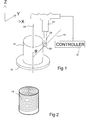
- Fig 1 is a perspective view of the object to be scanned
- an object 10, to be measured e.g. a tooth is mounted 12 on a mount of the coordinate positioning apparatus.
- the coordinate positioning apparatus has drive means (not shown) which enable translational movement of a probe 24 mounted on it along the x,y and z axes. Such movement is controlled by a machine controller 15.
- An axis of rotation 14 is specified by the user. This may for example be the z axis of the part coordinate system of the object.
- the rotational axis 14 may be defined with respect to the mount 12 by the object 10 being mechanically aligned to this axis when mounted on the mount.
- a second axis 16 is defined which is at an angle ⁇ to the rotation axis 14 and which intersects the surface of the object 10.
- the second axis 16 may be at any angle to the rotation axis 14 (but not parallel) and Fig 1 shows the second axis being at 45°.
- the second axis 16 is rotated about the axis of rotation 14 and is translated parallel to the axis of rotation 14 thus creating a spiral profile.
- Fig 2 illustrates the spiral profile 18 created by this movement of the second axis about the axis of rotation. As described in more detail below, a probe is moved along the spiral profile created by the movement of the second axis to scan the object along this spiral profile.
- Fig 3 illustrates the scan profile 20 created when the second axis is rotated a part revolution about the axis of rotation and translated parallel to the axis of rotation. This scan profile is suitable for use with a probe having a T stylus 22 as illustrated.
- a surface measurement probe 24 is mounted on the coordinate positioning apparatus for relative movement with respect to the mount 12.
- the probe 24 has a deflectable stylus 26 with a surface contacting tip 28.
- the probe 24 follows the spiral profile created by movement of the second axis 16 and thus scans the object 10 by following a spiral profile.
- the servo direction vector of the probe is directed along this second axis. This is the direction in which the probe is servoed by the coordinate positioning apparatus to control the stylus deflection of the probe (or for a non-contact probe, to control the offset of the probe.)
- Movement of the probe is controlled by an algorithm having two components.
- the first component keeps the probe on the second axis. This is accomplished by determining the position of the stylus tip of the probe, determining the nearest position on the second axis to the stylus tip and moving the probe in a direction perpendicular to the second axis back onto the second axis.
- the second component of the algorithm controls the probe deflection.
- the probe is moved parallel to the second axis to provide the desired probe deflection.
- the second axis has an angle of 45°. This is convenient for most applications because it will intersect with both the side and top surfaces, it enables both of these surfaces to be scanned in a single scan. This is particularly important where measurement of the top surface is important, for example for teeth.
- the second axis must be at an angle to the rotational axis and to the plane perpendicular to that axis.
- FIG 4 illustrates an object 30 having an undercut 32.
- the second axis was angled at 45° to the axis of rotation (shown by dashed line 34). This allows measurement of an undercut at an angle of 45° or below.
- An undercut having an angle of greater than 45° is not intersected by the second axis angled at 45° and thus cannot be scanned using this profile.
- the angle of the second axis is changed, for example to 90° to the axis of rotation, this new second axis 36 now intersects the undercut which can be scanned using the spiral profile.
- the angle of the second axis can be changed during the scan.
- objects with sharp undercuts can still be scanned in a single scan profile which has the advantage of enabling a fast scan. This is particularly relevant for scanning objects such as teeth which have undercuts.
- the angle of the second axis may be changed automatically using stylus deflection data to determine when to change the angle. For example, referring to fig 4 , the object 30 may be scanned upwards from at or near the bottom of the object using a horizontal second axis 36. When the stylus tip reaches the corner 38 of the undercut 32, the stylus will be deflected in -Z and the angle of the second axis will in response change automatically to 45°. Alternatively, the angle of the second axis may be changed at a predetermined position in Z.
- Rotation : cos ⁇ - sin ⁇ 0 sin ⁇ cos ⁇ 0 0 0 1
- Direction : Rotation 1 ⁇ 2 1 2 ⁇
- Direction is the sensor axis direction.
- Probe deflection is the actual probe deflection and "Nominal deflection” is the desired probe deflection.
- the probe deflection error is used to calculate the deflection control vector:
- PositionDemand ScanPositionDemand + ProbePositionDemand
- VelocityDemand PositionDemand - Machine ⁇ t
- the method is also suitable using a non-contact probe e.g. an optical, capacitance or inductance probe.
- a non-contact probe e.g. an optical, capacitance or inductance probe.
- the probe will need to be rotated to keep it directed at the surface of the object as the probe follows the spiral profile for example it may be directed towards the rotational axis of the spiral path.
- the direction in which the probe must face is known. Offset of the non-contact probe may be adjusted by moving the probe parallel to the second axis in a similar manner to how probe deflection is adjusted for a contact probe.
Landscapes
- Physics & Mathematics (AREA)
- General Physics & Mathematics (AREA)
- A Measuring Device Byusing Mechanical Method (AREA)
- Length Measuring Devices With Unspecified Measuring Means (AREA)
Claims (15)
- Une méthode pour scanner un objet dont le profil de surface est inconnu avec un palpeur de mesure de surface monté sur une machine de positionnement tridimensionnel, le palpeur ayant un vecteur de servo-direction définissable, la méthode comprenant les étapes suivantes ;
l'utilisation d'un mouvement de translation de la machine de positionnement tridimensionnel afin de déplacer le palpeur le long d'une trajectoire au moins en partie nominalement spirale, tournant autour d'un axe de ladite trajectoire, ledit axe étant disposé pour l'intersection avec l'objet ;
l'asservissement du palpeur dans la direction du vecteur de servo-direction par la machine de positionnement tridimensionnel afin de contrôler une déflexion du stylet ou un décalage du palpeur par rapport au profil de surface inconnu, dans lequel le vecteur de servo-direction est nominalement dirigé vers l'axe de la trajectoire au moins en partie nominalement spirale ;
et dans lequel le vecteur de servo-direction pour le palpeur est à un angle par rapport audit axe de la trajectoire nominalement spirale et à un angle par rapport au plan perpendiculaire audit axe de la trajectoire au moins en partie nominalement spirale. - Une méthode selon la revendication 1 dans laquelle l'objet a une surface de forme libre.
- Une méthode selon la revendication 1 ou la revendication 2 dans laquelle le palpeur de mesure de surface comprend un palpeur par contact muni d'un stylet capable d'être défléchi.
- Une méthode selon la revendication 3 dans laquelle la méthode comprend une étape supplémentaire comportant le déplacement du palpeur parallèlement à la direction du vecteur de servo-direction du palpeur afin de contrôler la déflexion du palpeur.
- Une méthode selon la revendication 1 ou la revendication 2 dans laquelle le palpeur de mesure de surface comprend un palpeur sans contact.
- Une méthode selon la revendication 5 dans laquelle la méthode comprend une étape supplémentaire comportant le déplacement du palpeur parallèlement à la direction du vecteur de servo-direction du palpeur afin de contrôler le décalage du palpeur.
- Une méthode selon la revendication 5 ou la revendication 6 dans laquelle, lorsque le palpeur se déplace le long de la trajectoire au moins en partie nominalement spirale, il pivote pour maintenir sa ligne de vue dirigée vers l'axe en intersection avec l'objet.
- Une méthode selon l'une quelconque des revendications précédentes selon laquelle la méthode comprend l'étape de maintien du palpeur sur la trajectoire nominalement spirale par un déplacement du palpeur perpendiculairement à la direction du vecteur de servo-direction du palpeur.
- Une méthode selon l'une quelconque des revendications précédentes selon laquelle le mouvement de translation de la machine de positionnement tridimensionnel afin de déplacer le palpeur le long de ladite trajectoire au moins en partie nominalement spirale est obtenu par :la définition d'un deuxième axe le long duquel le vecteur de servo-direction du palpeur est parallèle, ledit deuxième axe étant à un angle par rapport audit axe de ladite trajectoire ;la rotation du deuxième axe pour une révolution au moins partielle autour dudit axe de ladite trajectoire et la translation du deuxième axe dans une direction parallèle audit axe de ladite trajectoire ;le déplacement du palpeur de mesure de surface pour le maintenir sur le deuxième axe.
- Une méthode selon la revendication 9 dans laquelle le deuxième axe intersecte la surface de l'objet à mesurer.
- Une méthode selon l'une quelconque des revendications précédentes dans laquelle le vecteur de servo-direction du palpeur est à un angle de 45 degrés par rapport à l'axe en intersection avec la pièce.
- Une méthode selon l'une quelconque des revendications précédentes dans laquelle l'angle formé par le vecteur de direction du palpeur et l'axe en intersection avec l'objet est varié pendant le scanning.
- Appareil de scanning d'un objet ayant un profil de surface inconnu comprenant :un palpeur de mesure de surface monté sur une machine de positionnement tridimensionnel, ladite machine de positionnement tridimensionnel ayant un moyen d'entraînement permettant de piloter le palpeur selon un mouvement de translation sur plusieurs axes ; un contrôleur qui est disposé afin de contrôler ledit moyen d'entraînement permettant de déplacer le palpeur le long d'une trajectoire au moins en partie nominalement spirale, autour d'un axe de ladite trajectoire, ledit axe étant en intersection avec ledit objet ;dans lequel le contrôleur est disposé afin de contrôler le moyen d'entraînement de telle sorte que le palpeur est asservi dans la direction d'un vecteur de servo-direction pour contrôler la déflexion d'un stylet ou le décalage du palpeur par rapport au profil de surface inconnu, le vecteur de servo-direction étant dirigé nominalement vers ledit axe de la trajectoire au moins en partie nominalement spirale ;et dans lequel le contrôleur est disposé afin de contrôler le moyen d'entraînement de telle sorte que le vecteur de servo-direction du palpeur se trouve à un angle par rapport audit axe de la trajectoire au moins en partie nominalement spirale et à un angle par rapport à un plan perpendiculaire audit axe de la trajectoire au moins en partie nominalement spirale.
- Appareil de scanning d'un objet selon la revendication 13 dans lequel le contrôleur contrôle le moyen d'entraînement afin de maintenir le palpeur sur la trajectoire au moins en partie nominalement spirale par le déplacement du palpeur perpendiculairement à la direction du vecteur de servo-direction du palpeur.
- Appareil de scanning d'un objet selon la revendication 13 ou la revendication 14, dans lequel le mouvement de translation de la machine de positionnement tridimensionnel pour déplacer le palpeur le long de ladite trajectoire au moins en partie nominalement spirale est obtenu par :la définition d'un deuxième axe le long duquel le vecteur de servo-direction du palpeur est parallèle, ledit deuxième axe étant à un angle par rapport audit axe de ladite trajectoire ;la rotation du deuxième axe pour une révolution au moins partielle autour dudit axe de ladite trajectoire et la translation du deuxième axe dans une direction parallèle audit axe de ladite trajectoire ;le déplacement du palpeur de mesure de surface pour le maintenir sur le deuxième axe.
Applications Claiming Priority (3)
| Application Number | Priority Date | Filing Date | Title |
|---|---|---|---|
| GB0406110A GB0406110D0 (en) | 2004-03-18 | 2004-03-18 | Scanning an object |
| GB0406493A GB0406493D0 (en) | 2004-03-23 | 2004-03-23 | Scanning an object |
| PCT/GB2005/000965 WO2005090900A1 (fr) | 2004-03-18 | 2005-03-11 | Procede pour le balayage d'un objet |
Publications (2)
| Publication Number | Publication Date |
|---|---|
| EP1730465A1 EP1730465A1 (fr) | 2006-12-13 |
| EP1730465B1 true EP1730465B1 (fr) | 2015-05-20 |
Family
ID=34961971
Family Applications (1)
| Application Number | Title | Priority Date | Filing Date |
|---|---|---|---|
| EP20050718021 Expired - Lifetime EP1730465B1 (fr) | 2004-03-18 | 2005-03-11 | Procede pour le balayage d'un objet |
Country Status (4)
| Country | Link |
|---|---|
| US (1) | US20080021672A1 (fr) |
| EP (1) | EP1730465B1 (fr) |
| JP (1) | JP2007529734A (fr) |
| WO (1) | WO2005090900A1 (fr) |
Families Citing this family (20)
| Publication number | Priority date | Publication date | Assignee | Title |
|---|---|---|---|---|
| GB0605796D0 (en) | 2006-03-23 | 2006-05-03 | Renishaw Plc | Apparatus and method of measuring workpieces |
| JP5221004B2 (ja) * | 2006-05-25 | 2013-06-26 | 株式会社ミツトヨ | 測定装置、表面性状測定方法、及び表面性状測定プログラム |
| GB0703423D0 (en) * | 2007-02-22 | 2007-04-04 | Renishaw Plc | Calibration method and apparatus |
| GB0707921D0 (en) * | 2007-04-24 | 2007-05-30 | Renishaw Plc | Apparatus and method for surface measurement |
| US9689655B2 (en) | 2008-10-29 | 2017-06-27 | Renishaw Plc | Measurement method |
| JP5269698B2 (ja) * | 2009-06-10 | 2013-08-21 | 株式会社ミツトヨ | 真円度測定装置 |
| US8652204B2 (en) | 2010-04-01 | 2014-02-18 | Medtronic, Inc. | Transcatheter valve with torsion spring fixation and related systems and methods |
| WO2012037059A1 (fr) * | 2010-09-13 | 2012-03-22 | Hexagon Technology Center Gmbh | Procédé et appareil pour commander une machine de mesure de coordonnées à balayage de surface |
| JP5763419B2 (ja) | 2011-05-27 | 2015-08-12 | 株式会社ミツトヨ | 断面形状測定方法 |
| JP5984406B2 (ja) * | 2012-02-01 | 2016-09-06 | キヤノン株式会社 | 測定装置 |
| US9726481B2 (en) | 2012-04-18 | 2017-08-08 | Renishaw Plc | Method of analogue measurement scanning on a machine tool |
| US10037017B2 (en) * | 2012-04-18 | 2018-07-31 | Renishaw Plc | Method of measurement on a machine tool and corresponding machine tool apparatus |
| WO2013156767A1 (fr) | 2012-04-18 | 2013-10-24 | Renishaw Plc | Procédé pour la recherche d'une caractéristique au moyen d'une machine-outil |
| US9417047B2 (en) * | 2014-08-11 | 2016-08-16 | Toyota Motor Engineering & Manufacturing North America, Inc. | Three-dimensional edge profile determination |
| IT201700096656A1 (it) | 2017-08-28 | 2019-02-28 | Cosmogas Srl | Scambiatore di calore per una caldaia, e tubo di scambiatore di calore |
| DE102019220060A1 (de) * | 2019-12-18 | 2021-06-24 | Carl Zeiss Industrielle Messtechnik Gmbh | Verfahren zum Kalibrieren eines taktilen Sensors |
| EP4235325B1 (fr) * | 2020-04-21 | 2024-12-25 | Carl Zeiss Industrielle Messtechnik GmbH | Procédé et dispositif de détermination des points de mesure d'une bande de mesure adaptée à la mesure d'un objet de mesure au moyen d'un dispositif de mesure de coordonnés ainsi que programme |
| DE102020111146B4 (de) | 2020-04-23 | 2025-10-30 | Carl Zeiss Industrielle Messtechnik Gmbh | Verfahren und Vorrichtung zum Bestimmen von dimensionalen und/oder geometrischen Eigenschaften eines Messobjekts |
| CN113251949B (zh) * | 2021-06-18 | 2021-11-30 | 三代光学科技(天津)有限公司 | 一种微透镜阵列面形的单点光学测量路径生成方法 |
| US12504266B2 (en) * | 2023-06-27 | 2025-12-23 | Raytheon Company | Flatness testing for cathodes |
Family Cites Families (9)
| Publication number | Priority date | Publication date | Assignee | Title |
|---|---|---|---|---|
| US5189806A (en) * | 1988-12-19 | 1993-03-02 | Renishaw Plc | Method of and apparatus for scanning the surface of a workpiece |
| SE501410C2 (sv) * | 1993-07-12 | 1995-02-06 | Nobelpharma Ab | Förfarande och anordning i samband med framställning av tand, brygga, etc |
| SE501411C2 (sv) * | 1993-07-12 | 1995-02-06 | Nobelpharma Ab | Förfarande och anordning vid tredimensionell kropp användbar i människokroppen |
| DE19809589B4 (de) | 1998-03-06 | 2009-04-02 | Carl Zeiss Industrielle Messtechnik Gmbh | Verfahren zur Kalibrierung eines Tasters eines Koordinatenmeßgerätes |
| TW550375B (en) * | 2001-09-07 | 2003-09-01 | Olympus Optical Co | Apparatus for measuring a surface profile |
| GB0126232D0 (en) * | 2001-11-01 | 2002-01-02 | Renishaw Plc | Calibration of an analogue probe |
| US7185552B2 (en) | 2001-11-27 | 2007-03-06 | Renishaw Plc | Movable sample holder |
| GB0329098D0 (en) * | 2003-12-16 | 2004-01-21 | Renishaw Plc | Method of calibrating a scanning system |
| JP4705792B2 (ja) * | 2005-03-17 | 2011-06-22 | 株式会社ミツトヨ | 軸間角度補正方法 |
-
2005
- 2005-03-11 US US10/590,880 patent/US20080021672A1/en not_active Abandoned
- 2005-03-11 EP EP20050718021 patent/EP1730465B1/fr not_active Expired - Lifetime
- 2005-03-11 WO PCT/GB2005/000965 patent/WO2005090900A1/fr not_active Ceased
- 2005-03-11 JP JP2007503400A patent/JP2007529734A/ja active Pending
Also Published As
| Publication number | Publication date |
|---|---|
| EP1730465A1 (fr) | 2006-12-13 |
| JP2007529734A (ja) | 2007-10-25 |
| WO2005090900A1 (fr) | 2005-09-29 |
| US20080021672A1 (en) | 2008-01-24 |
Similar Documents
| Publication | Publication Date | Title |
|---|---|---|
| EP1730465B1 (fr) | Procede pour le balayage d'un objet | |
| JP5350216B2 (ja) | 加工品の測定装置および測定方法 | |
| EP1978328B1 (fr) | Sonde à balayage oscillant avec force de contact constante | |
| EP1877728B1 (fr) | Procede de planification de trajet | |
| EP2364427B1 (fr) | Methode pour un système de mesure de coordonnées | |
| US7543393B2 (en) | Method of calibrating a scanning system | |
| US7676942B2 (en) | Multi-axis positioning and measuring system and method of using | |
| JP5665270B2 (ja) | 工作物の表面を走査する方法 | |
| EP2764324B1 (fr) | Procédé et dispositif de localisation d'une caractéristique d'un objet | |
| JP4504818B2 (ja) | 加工物検査方法 | |
| US7376261B2 (en) | Surface scan measuring device and method of forming compensation table for scanning probe | |
| CN109964098B (zh) | 坐标定位设备以及操作方法 | |
| EP1792139B1 (fr) | Utilisation de sondes de mesure de surface | |
| KR20170031815A (ko) | 프로브 회전형 원자현미경의 프로브 정렬도 측정 방법 | |
| CN1934409B (zh) | 物体扫描 | |
| JPH0886640A (ja) | 形状測定方法及び装置 | |
| EP4563935A1 (fr) | Procédé de détermination d'informations concernant une ou plusieurs dépressions dans une pièce |
Legal Events
| Date | Code | Title | Description |
|---|---|---|---|
| PUAI | Public reference made under article 153(3) epc to a published international application that has entered the european phase |
Free format text: ORIGINAL CODE: 0009012 |
|
| 17P | Request for examination filed |
Effective date: 20061016 |
|
| AK | Designated contracting states |
Kind code of ref document: A1 Designated state(s): AT BE BG CH CY CZ DE DK EE ES FI FR GB GR HU IE IS IT LI LT LU MC NL PL PT RO SE SI SK TR |
|
| DAX | Request for extension of the european patent (deleted) | ||
| 17Q | First examination report despatched |
Effective date: 20101109 |
|
| GRAP | Despatch of communication of intention to grant a patent |
Free format text: ORIGINAL CODE: EPIDOSNIGR1 |
|
| GRAJ | Information related to disapproval of communication of intention to grant by the applicant or resumption of examination proceedings by the epo deleted |
Free format text: ORIGINAL CODE: EPIDOSDIGR1 |
|
| GRAP | Despatch of communication of intention to grant a patent |
Free format text: ORIGINAL CODE: EPIDOSNIGR1 |
|
| INTG | Intention to grant announced |
Effective date: 20141212 |
|
| INTG | Intention to grant announced |
Effective date: 20141223 |
|
| GRAS | Grant fee paid |
Free format text: ORIGINAL CODE: EPIDOSNIGR3 |
|
| GRAA | (expected) grant |
Free format text: ORIGINAL CODE: 0009210 |
|
| AK | Designated contracting states |
Kind code of ref document: B1 Designated state(s): AT BE BG CH CY CZ DE DK EE ES FI FR GB GR HU IE IS IT LI LT LU MC NL PL PT RO SE SI SK TR |
|
| REG | Reference to a national code |
Ref country code: GB Ref legal event code: FG4D |
|
| REG | Reference to a national code |
Ref country code: CH Ref legal event code: EP |
|
| REG | Reference to a national code |
Ref country code: AT Ref legal event code: REF Ref document number: 727947 Country of ref document: AT Kind code of ref document: T Effective date: 20150615 Ref country code: CH Ref legal event code: NV Representative=s name: KIRKER AND CIE S.A., CH |
|
| REG | Reference to a national code |
Ref country code: IE Ref legal event code: FG4D |
|
| REG | Reference to a national code |
Ref country code: DE Ref legal event code: R096 Ref document number: 602005046587 Country of ref document: DE Effective date: 20150625 |
|
| REG | Reference to a national code |
Ref country code: AT Ref legal event code: MK05 Ref document number: 727947 Country of ref document: AT Kind code of ref document: T Effective date: 20150520 |
|
| REG | Reference to a national code |
Ref country code: LT Ref legal event code: MG4D |
|
| REG | Reference to a national code |
Ref country code: NL Ref legal event code: MP Effective date: 20150520 |
|
| PG25 | Lapsed in a contracting state [announced via postgrant information from national office to epo] |
Ref country code: PT Free format text: LAPSE BECAUSE OF FAILURE TO SUBMIT A TRANSLATION OF THE DESCRIPTION OR TO PAY THE FEE WITHIN THE PRESCRIBED TIME-LIMIT Effective date: 20150921 Ref country code: ES Free format text: LAPSE BECAUSE OF FAILURE TO SUBMIT A TRANSLATION OF THE DESCRIPTION OR TO PAY THE FEE WITHIN THE PRESCRIBED TIME-LIMIT Effective date: 20150520 Ref country code: LT Free format text: LAPSE BECAUSE OF FAILURE TO SUBMIT A TRANSLATION OF THE DESCRIPTION OR TO PAY THE FEE WITHIN THE PRESCRIBED TIME-LIMIT Effective date: 20150520 Ref country code: FI Free format text: LAPSE BECAUSE OF FAILURE TO SUBMIT A TRANSLATION OF THE DESCRIPTION OR TO PAY THE FEE WITHIN THE PRESCRIBED TIME-LIMIT Effective date: 20150520 |
|
| PG25 | Lapsed in a contracting state [announced via postgrant information from national office to epo] |
Ref country code: AT Free format text: LAPSE BECAUSE OF FAILURE TO SUBMIT A TRANSLATION OF THE DESCRIPTION OR TO PAY THE FEE WITHIN THE PRESCRIBED TIME-LIMIT Effective date: 20150520 Ref country code: IS Free format text: LAPSE BECAUSE OF FAILURE TO SUBMIT A TRANSLATION OF THE DESCRIPTION OR TO PAY THE FEE WITHIN THE PRESCRIBED TIME-LIMIT Effective date: 20150920 Ref country code: BG Free format text: LAPSE BECAUSE OF FAILURE TO SUBMIT A TRANSLATION OF THE DESCRIPTION OR TO PAY THE FEE WITHIN THE PRESCRIBED TIME-LIMIT Effective date: 20150820 Ref country code: GR Free format text: LAPSE BECAUSE OF FAILURE TO SUBMIT A TRANSLATION OF THE DESCRIPTION OR TO PAY THE FEE WITHIN THE PRESCRIBED TIME-LIMIT Effective date: 20150821 |
|
| PG25 | Lapsed in a contracting state [announced via postgrant information from national office to epo] |
Ref country code: DK Free format text: LAPSE BECAUSE OF FAILURE TO SUBMIT A TRANSLATION OF THE DESCRIPTION OR TO PAY THE FEE WITHIN THE PRESCRIBED TIME-LIMIT Effective date: 20150520 Ref country code: EE Free format text: LAPSE BECAUSE OF FAILURE TO SUBMIT A TRANSLATION OF THE DESCRIPTION OR TO PAY THE FEE WITHIN THE PRESCRIBED TIME-LIMIT Effective date: 20150520 |
|
| REG | Reference to a national code |
Ref country code: DE Ref legal event code: R097 Ref document number: 602005046587 Country of ref document: DE |
|
| PG25 | Lapsed in a contracting state [announced via postgrant information from national office to epo] |
Ref country code: SK Free format text: LAPSE BECAUSE OF FAILURE TO SUBMIT A TRANSLATION OF THE DESCRIPTION OR TO PAY THE FEE WITHIN THE PRESCRIBED TIME-LIMIT Effective date: 20150520 Ref country code: CZ Free format text: LAPSE BECAUSE OF FAILURE TO SUBMIT A TRANSLATION OF THE DESCRIPTION OR TO PAY THE FEE WITHIN THE PRESCRIBED TIME-LIMIT Effective date: 20150520 Ref country code: RO Free format text: LAPSE BECAUSE OF NON-PAYMENT OF DUE FEES Effective date: 20150520 Ref country code: PL Free format text: LAPSE BECAUSE OF FAILURE TO SUBMIT A TRANSLATION OF THE DESCRIPTION OR TO PAY THE FEE WITHIN THE PRESCRIBED TIME-LIMIT Effective date: 20150520 |
|
| PLBE | No opposition filed within time limit |
Free format text: ORIGINAL CODE: 0009261 |
|
| STAA | Information on the status of an ep patent application or granted ep patent |
Free format text: STATUS: NO OPPOSITION FILED WITHIN TIME LIMIT |
|
| 26N | No opposition filed |
Effective date: 20160223 |
|
| PG25 | Lapsed in a contracting state [announced via postgrant information from national office to epo] |
Ref country code: SI Free format text: LAPSE BECAUSE OF FAILURE TO SUBMIT A TRANSLATION OF THE DESCRIPTION OR TO PAY THE FEE WITHIN THE PRESCRIBED TIME-LIMIT Effective date: 20150520 |
|
| PG25 | Lapsed in a contracting state [announced via postgrant information from national office to epo] |
Ref country code: BE Free format text: LAPSE BECAUSE OF FAILURE TO SUBMIT A TRANSLATION OF THE DESCRIPTION OR TO PAY THE FEE WITHIN THE PRESCRIBED TIME-LIMIT Effective date: 20150520 |
|
| PG25 | Lapsed in a contracting state [announced via postgrant information from national office to epo] |
Ref country code: MC Free format text: LAPSE BECAUSE OF FAILURE TO SUBMIT A TRANSLATION OF THE DESCRIPTION OR TO PAY THE FEE WITHIN THE PRESCRIBED TIME-LIMIT Effective date: 20150520 Ref country code: LU Free format text: LAPSE BECAUSE OF FAILURE TO SUBMIT A TRANSLATION OF THE DESCRIPTION OR TO PAY THE FEE WITHIN THE PRESCRIBED TIME-LIMIT Effective date: 20160311 |
|
| REG | Reference to a national code |
Ref country code: IE Ref legal event code: MM4A |
|
| REG | Reference to a national code |
Ref country code: FR Ref legal event code: ST Effective date: 20161130 |
|
| PG25 | Lapsed in a contracting state [announced via postgrant information from national office to epo] |
Ref country code: FR Free format text: LAPSE BECAUSE OF NON-PAYMENT OF DUE FEES Effective date: 20160331 Ref country code: IE Free format text: LAPSE BECAUSE OF NON-PAYMENT OF DUE FEES Effective date: 20160311 |
|
| PGFP | Annual fee paid to national office [announced via postgrant information from national office to epo] |
Ref country code: CH Payment date: 20170322 Year of fee payment: 13 Ref country code: DE Payment date: 20170322 Year of fee payment: 13 |
|
| PG25 | Lapsed in a contracting state [announced via postgrant information from national office to epo] |
Ref country code: NL Free format text: LAPSE BECAUSE OF FAILURE TO SUBMIT A TRANSLATION OF THE DESCRIPTION OR TO PAY THE FEE WITHIN THE PRESCRIBED TIME-LIMIT Effective date: 20150520 Ref country code: SE Free format text: LAPSE BECAUSE OF FAILURE TO SUBMIT A TRANSLATION OF THE DESCRIPTION OR TO PAY THE FEE WITHIN THE PRESCRIBED TIME-LIMIT Effective date: 20150520 |
|
| PGFP | Annual fee paid to national office [announced via postgrant information from national office to epo] |
Ref country code: IT Payment date: 20170327 Year of fee payment: 13 |
|
| PG25 | Lapsed in a contracting state [announced via postgrant information from national office to epo] |
Ref country code: CY Free format text: LAPSE BECAUSE OF FAILURE TO SUBMIT A TRANSLATION OF THE DESCRIPTION OR TO PAY THE FEE WITHIN THE PRESCRIBED TIME-LIMIT Effective date: 20150520 Ref country code: HU Free format text: LAPSE BECAUSE OF FAILURE TO SUBMIT A TRANSLATION OF THE DESCRIPTION OR TO PAY THE FEE WITHIN THE PRESCRIBED TIME-LIMIT; INVALID AB INITIO Effective date: 20050311 |
|
| PG25 | Lapsed in a contracting state [announced via postgrant information from national office to epo] |
Ref country code: TR Free format text: LAPSE BECAUSE OF FAILURE TO SUBMIT A TRANSLATION OF THE DESCRIPTION OR TO PAY THE FEE WITHIN THE PRESCRIBED TIME-LIMIT Effective date: 20150520 |
|
| REG | Reference to a national code |
Ref country code: DE Ref legal event code: R119 Ref document number: 602005046587 Country of ref document: DE |
|
| REG | Reference to a national code |
Ref country code: CH Ref legal event code: PL |
|
| PG25 | Lapsed in a contracting state [announced via postgrant information from national office to epo] |
Ref country code: DE Free format text: LAPSE BECAUSE OF NON-PAYMENT OF DUE FEES Effective date: 20181002 |
|
| PG25 | Lapsed in a contracting state [announced via postgrant information from national office to epo] |
Ref country code: CH Free format text: LAPSE BECAUSE OF NON-PAYMENT OF DUE FEES Effective date: 20180331 Ref country code: IT Free format text: LAPSE BECAUSE OF NON-PAYMENT OF DUE FEES Effective date: 20180311 Ref country code: LI Free format text: LAPSE BECAUSE OF NON-PAYMENT OF DUE FEES Effective date: 20180331 |
|
| PGFP | Annual fee paid to national office [announced via postgrant information from national office to epo] |
Ref country code: GB Payment date: 20200327 Year of fee payment: 16 |
|
| GBPC | Gb: european patent ceased through non-payment of renewal fee |
Effective date: 20210311 |
|
| PG25 | Lapsed in a contracting state [announced via postgrant information from national office to epo] |
Ref country code: GB Free format text: LAPSE BECAUSE OF NON-PAYMENT OF DUE FEES Effective date: 20210311 |