EP1731477A2 - Kommissionierflotte - Google Patents
Kommissionierflotte Download PDFInfo
- Publication number
- EP1731477A2 EP1731477A2 EP06011621A EP06011621A EP1731477A2 EP 1731477 A2 EP1731477 A2 EP 1731477A2 EP 06011621 A EP06011621 A EP 06011621A EP 06011621 A EP06011621 A EP 06011621A EP 1731477 A2 EP1731477 A2 EP 1731477A2
- Authority
- EP
- European Patent Office
- Prior art keywords
- picking
- order picker
- drive part
- control station
- drive
- Prior art date
- Legal status (The legal status is an assumption and is not a legal conclusion. Google has not performed a legal analysis and makes no representation as to the accuracy of the status listed.)
- Granted
Links
Images



Classifications
-
- B—PERFORMING OPERATIONS; TRANSPORTING
- B62—LAND VEHICLES FOR TRAVELLING OTHERWISE THAN ON RAILS
- B62B—HAND-PROPELLED VEHICLES, e.g. HAND CARTS OR PERAMBULATORS; SLEDGES
- B62B3/00—Hand carts having more than one axis carrying transport wheels; Steering devices therefor; Equipment therefor
- B62B3/04—Hand carts having more than one axis carrying transport wheels; Steering devices therefor; Equipment therefor involving means for grappling or securing in place objects to be carried; Loading or unloading equipment
- B62B3/06—Hand carts having more than one axis carrying transport wheels; Steering devices therefor; Equipment therefor involving means for grappling or securing in place objects to be carried; Loading or unloading equipment for simply clearing the load from the ground
- B62B3/0612—Hand carts having more than one axis carrying transport wheels; Steering devices therefor; Equipment therefor involving means for grappling or securing in place objects to be carried; Loading or unloading equipment for simply clearing the load from the ground power operated
-
- B—PERFORMING OPERATIONS; TRANSPORTING
- B62—LAND VEHICLES FOR TRAVELLING OTHERWISE THAN ON RAILS
- B62D—MOTOR VEHICLES; TRAILERS
- B62D51/00—Motor vehicles characterised by the driver not being seated
- B62D51/02—Motor vehicles characterised by the driver not being seated the driver standing in the vehicle
-
- B—PERFORMING OPERATIONS; TRANSPORTING
- B66—HOISTING; LIFTING; HAULING
- B66F—HOISTING, LIFTING, HAULING OR PUSHING, NOT OTHERWISE PROVIDED FOR, e.g. DEVICES WHICH APPLY A LIFTING OR PUSHING FORCE DIRECTLY TO THE SURFACE OF A LOAD
- B66F9/00—Devices for lifting or lowering bulky or heavy goods for loading or unloading purposes
- B66F9/06—Devices for lifting or lowering bulky or heavy goods for loading or unloading purposes movable, with their loads, on wheels or the like, e.g. fork-lift trucks
-
- B—PERFORMING OPERATIONS; TRANSPORTING
- B66—HOISTING; LIFTING; HAULING
- B66F—HOISTING, LIFTING, HAULING OR PUSHING, NOT OTHERWISE PROVIDED FOR, e.g. DEVICES WHICH APPLY A LIFTING OR PUSHING FORCE DIRECTLY TO THE SURFACE OF A LOAD
- B66F9/00—Devices for lifting or lowering bulky or heavy goods for loading or unloading purposes
- B66F9/06—Devices for lifting or lowering bulky or heavy goods for loading or unloading purposes movable, with their loads, on wheels or the like, e.g. fork-lift trucks
- B66F9/075—Constructional features or details
- B66F9/07513—Details concerning the chassis
- B66F9/07531—Battery compartments
-
- B—PERFORMING OPERATIONS; TRANSPORTING
- B62—LAND VEHICLES FOR TRAVELLING OTHERWISE THAN ON RAILS
- B62B—HAND-PROPELLED VEHICLES, e.g. HAND CARTS OR PERAMBULATORS; SLEDGES
- B62B5/00—Accessories or details specially adapted for hand carts
- B62B5/08—Children's seats ; Seats or supports for other persons
- B62B5/087—Platforms to stand upon
Definitions
- the invention relates to a picking fleet, comprising at least one horizontal order picker, which has a drive part, a load part and an operator between the drive part and the load part arranged control station for an operator, wherein the load part is arranged liftably by means of a lifting device on the drive part, and at least one vertical order picker a drive part, a load part and arranged between the drive part and the load part control station for an operator, wherein the load part arranged on the control station and the control station by means of a lifting device on the drive part is arranged liftable.
- Order pickers trained as horizontal order pickers and vertical order pickers can be found in the product range of all major manufacturers of industrial trucks.
- the various order pickers of a manufacturer, trained as vertical and horizontal order pickers, are summarized in this patent application under the term picking fleet.
- Horizontal order pickers have a liftable load section that can lift a load for transport by about 10-20 cm, these horizontal order pickers being also referred to as low lift order pickers.
- Horizontal order pickers are hereby used for picking goods at the first shelf level in warehouses, wherein the operating stand can be designed to be fixed or liftable in order to enable the operator to continue picking goods from the second shelf level in the warehouse.
- Horizontal order pickers in this case generally have a construction in which the load part, the control station and a battery block relative to a drive part, which is provided with a traction drive unit and a linear actuator can be raised by means of a lifting device designed as Initialhub nails.
- Vertikalkommissionerer in which the load part are arranged on the liftable control station, in an embodiment with the lowest stroke of the control station already have a picking height of at least 3.5 m and thus allow a removal of goods from the third shelf level of a warehouse and are referred to depending on the lifting height as Mittelhub- or Hochhubkommissionierer.
- Vertical order picker in this case have a construction in which the control station together with the load part by means of a lifting device designed as a lifting device relative to the drive part, which is provided with the traction drive, the linear actuator and the battery pack, can be raised.
- the object of the present invention is to provide a picking fleet consisting of horizontal picking and vertical picking, which can be produced with a low manufacturing outlay.
- At least one horizontal order picker the picking fleet and at least one vertical order picking the order picking fleet have a drive part having a frame on the front in the main direction of a drive, in particular a traction drive unit and / or a linear actuator, is attachable to the behind the drive in the main direction of a battery compartment for receiving a battery pack is formed, wherein on the frame in the main direction behind the battery compartment and in front of the operator of the control console can be fastened.
- the load part of the horizontal order picker or the load rollers of the vertical order picker can be fastened to the frame of the drive part adjacent to the control station in the main direction behind the operator.
- the load part can be arranged in a simple manner for a horizontal order picker behind the control station and for a vertical order picker, in which the load part is arranged on the liftable control station, behind the liftable control stand, the load rollers are attached to the drive part and thus with a nearly identical frame drive parts for horizontal order picker and vertical order picker the picking fleet are produced.
- the frame of the drive part has two lateral side members which extend along the operating position, wherein the operating stand and / or the load part can be fastened to the longitudinal members.
- the longitudinal members of the frame of the drive part can be attached in a simple manner and with low construction costs of the control station and the load part of a horizontal order picker and provided with the load part liftable operating a vertical order picker.
- the traction drive unit is mounted centrally and rigidly on the frame of the traction drive.
- a drive part By located on the vehicle center line and thus central arrangement of a trained as a steerable traction motor travel drive unit can be used with little construction effort, a drive part with the same arrangement of an identical drive unit for producing a horizontal order picker and a vertical order picker.
- the drive part is provided with receptacles for lateral support rollers. This makes it possible in a simple manner, at the To arrange drive part to increase the driving stability and stability of a horizontal order picker or a vertical order ionizer spring-loaded support rollers.
- a lifting drive with low power can be easily installed in the drive part of a horizontal order picker having a load part with a low lifting height and / or a fixed operating stand and in the drive part a vertical order picker, which has a load part with a larger lifting height and / or a liftable control stand, a lifting drive with a correspondingly higher power to be installed and thus the lifting drive of the drive part to the various embodiments of the order picking the order picking fleet.
- control station is provided with an operating device, in particular a control elements having handlebars.
- an operating device in particular a control elements having handlebars.
- horizontal order pickers and vertical order pickers of the picking fleet can be controlled in a simple manner by an operator.
- the operating device is arranged here in an advantageous manner on a control panel, which extends in the main direction forward. With such, extending forward over the battery compartment control panel no additional space in the longitudinal direction of the horizontal order picker and vertical order picker is required for the operating device.
- the operator of the horizontal order picker can be designed as a fixed or liftable operator.
- On the drive part in the main direction behind the battery compartment different operating levels of a horizontal order picker can be easily attached, which can be easily produced with a drive part different embodiments of Horizontalkommissionierem with multiple variants of operator stations.
- a mast is attached.
- a simple attachment of the fixed control station or the liftable control station on the drive part is in this case achievable when the frame of the drive part, in particular the side rails, lateral vertical support can be fastened, where the fixed control station is arranged or the fixed portion of the mast of the liftable control stand of the horizontal order picker.
- the lifting device for lifting the load part of the horizontal order picker on the frame of the drive part, in particular the side rails, in the main direction behind the control stand can be fastened.
- the lifting device of the load part of the horizontal order picker is thus arranged in the main direction behind the control station.
- the mast of a liftable operator's station is located in the main direction of travel in front of the control station.
- the lifting device of the horizontal picker expediently has lateral vertical profiles which can be fastened to the frame of the drive part, in particular the longitudinal members, whereby the liftable load part can be arranged on the drive part with little construction effort.
- the lifting device of the horizontal order picker is designed as Initialhub listening and / or as a mast.
- horizontal order pickers can be made with an initial stroke that allows a lift height of about 15-20 cm to transport a load, and horizontal order picker with arranged on a mast lifting device having an increased lifting height, thereby easily with a drive part different horizontal order picker with several variants of load parts can be produced.
- the mast can be provided here as an alternative to an Initialhub vibration or in addition to the Initialhub coupled to achieve a 1925hubes.
- a rear wall of the operating stand is arranged with particular advantage.
- the lifting device for raising the operating level of the vertical order picker is designed according to an embodiment of the invention as a mast which can be fastened to the frame of the drive part, in particular the longitudinal members.
- the mast of the control station of the vertical order picker can be fastened to the drive part in a simple manner when the mast has lateral vertical profiles which can be fastened to the frame of the drive part, in particular the longitudinal struts.
- the longitudinal members of the frame of the drive part are expediently provided with the load rollers, which can be easily arranged at a vertical order picker, the load rollers on the drive part in the main direction behind the operator.
- Different variants of vertical order pickers can be made in a simple manner, when the load part of the vertical order picker comprises a fixed or liftable load part, which is arranged on the liftable operating part, wherein an additional lift can be achieved by a liftable load part.
- the load part of the vertical order picker is expediently liftable by means of a lifting mast, wherein the mast is attached to a standing platform of the control station.
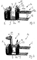
- Figures 1 a, 1 b show a first embodiment of a horizontal order picker 1 a according to the invention a picking fleet.
- the horizontal order picker 1 a has in the main direction of HF on a front arranged drive part A and arranged at the rear area, liftable load part L, wherein between the drive part A and load part L an operator's stand B is arranged for an operator.
- the drive part A has, as a load-bearing component, a frame 2 which comprises two lateral side members 2a, 2b which extend along the operating part B in the vehicle longitudinal direction.
- a drive is arranged in the main direction HF front of the frame 2 in a manner not shown, comprising a centrally and rigidly arranged electric traction unit, which includes a traction motor and a steering motor for rotating the traction motor, and not further shown Has aggregates, such as a power electronics unit and an electric lifting drive.
- the frame 2 of the drive part A is further provided with not shown receptacles for lateral, spring-loaded support rollers.
- a battery compartment 4 is further formed for receiving a battery pack, which is arranged adjacent in the main direction of travel HF and behind the arranged under the hood 2 drive.
- the control station B is arranged on the frame 2 or the longitudinal members 2a, 2b of the drive part A of the horizontal order picker 1a.
- the control station B is designed as a fixed control station and has a standing platform 5 and a control panel 6, wherein the control station B in the main direction HF in front of standing on the platform platform 5 operator on the frame 2 and the longitudinal beams 2a, 2b is attached.
- the control station B is in this case arranged on lateral vertical supports 7, which are arranged and fastened on the frame 2 or the longitudinal members 2a, 2b in the main driving direction HF behind the battery compartment 4 and in front of the operator located on the platform 5.
- the control panel 6 extends in this case in the main direction of travel HF forward over the battery compartment 4 and is provided with an operating device 8, which is formed for example as control elements having handlebars.
- a lifting device 10 which has lateral vertical profiles 9 which are arranged and fixed in the main driving direction HF behind the operating stand B at the rear end region of the frame 2 or the side members 2a, 2b.
- the lifting device 10 is designed as Initialhub Road by means of a lifting carriage 11, are arranged on the load arms 12, in which load rollers 13 are pivotally mounted in the vertical profiles 9 can be raised or lowered.
- FIGS. 1a, and 1b which has a fixed operating position B and a lifting part L which can be lifted by means of a lifting device 10 designed as an initial lifting device, is shown in FIG. 1a with a lowered load part L and in FIG. 1b with a lifted load part L shown.
- FIG. 2 shows a second embodiment of the horizontal order picker 1a with a raisable operating part B and a load part L, which can be raised by means of a lifting device 10 designed as an initial lifting device.
- the operating device 8 on the control panel 6 of the liftable control station B is - as can be seen from the figure 2 - with raised control station B in a simple way, an operation of the horizontal order picker 1 possible.
- FIG. 3 shows a third embodiment of the horizontal order picker 1 a with a fixed operating stand B and a load part L, the lifting device 10 furthermore having a lifting mast 17, which is arranged on the lifting slide 11 of the initial lifting device and, in a further development of FIGS thus forms a 1925hub.
- the mast 17 a provided with lifting arms 12a load carriage 11a is arranged liftably, wherein the load rollers 13 are arranged on the means of the Initialhub issued liftable load arms 12.
- the control station B is arranged on the lateral vertical support 7, which are fastened to the frame 2 or the longitudinal members 2 a, 2 b of the drive part A.
- the horizontal order picker 1 a is shown with lowered Initialhub observed and raised mast 17 of the load part L.
- FIG. 4 shows a fourth embodiment of a horizontal order picker 1 a with a load part L designed according to FIG. 3, which has a lifting device 10 designed as a lifting mast 17 in addition to the initial lifting device, and with a liftable operating stand B according to FIG vertical support 7 comprehensive mast 15 can be raised or lowered.
- the horizontal order taker 1a is shown with raised control station B and raised mast 17 of the load part L, wherein the Initialhub responded the load part L is in the lowered position.
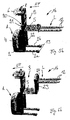
- FIGS. 5a, 5b show a first embodiment of a vertical order picker 1b of the picking fleet.
- the vertical Commissioner 1 b is derived from the drive part A according to Figures 1 to 4 and has a liftable control station B, on which the load part L is attached.
- the control station B is in this case attached to the frame 2 of the drive part A in the main direction of travel HF behind the battery compartment 4 and in front of the operator located on the standing platform 5.
- the liftable, formed by the platform platform 5 and the control elements 8 with the control panel 6 formed operating stand B can be raised or lowered by means of a lifting frame 21 with lateral vertical profiles 22 lifting device 20, wherein the profiles 22, the fixed portion of the mast 21st form on the frame 2 and the longitudinal beams 2a, 2b of the drive part A in the main direction of travel HF behind the battery compartment 4 and in front of the operator located on the platform 5 and are mounted.
- the load part L is designed as a fixed load part L and has load arms 12, which are fastened to the standing platform 5 of the control station B.
- the load rollers 13 are hereby arranged on the longitudinal members 2a, 2b of the drive part A in the main direction of travel HF behind the operator standing on the platform 5.
- FIG. 5a shows the vertical order picker 1b with the operator station B lowered and thus the load part L lowered.
- the operator station B with the load part L is shown in the raised position.
- FIG. 6 a shows the vertical order picker 1 b with the operator station B lowered and the mast 23 lowered.
- FIG. 6 b shows the vertical order picker 1 b with the operator console B raised and the mast 23 raised.
- the embodiments of the horizontal order picker 1a shown in FIGS. 1a to 4a and the embodiments of the vertical order picker 1b shown in FIGS. 5a to 6b are all components of a picking fleet which can be produced in a production plant for pickers using a substantially identical drive part A, at the frame 2 in the main direction HF front of a drive, in particular a central and rigidly arranged traction drive unit and / or a linear actuator is attached, is formed in the main direction of travel HF behind the drive, the battery compartment 4 for receiving a battery pack and behind in the main direction of travel HF the battery compartment 4 and in front of standing on the platform platform 5 operator of the control station B is attached.
- this drive part A On the frame 2 of this drive part A can be formed by attaching a load part L behind the control station B a horizontal order picker 1 a, the control station B can be configured fixed or raised.
- a vertical order picker 1b By arranging load rollers 13 on the frame 2 of the drive part A behind the control station B and using a control station B with load part L arranged thereon, a vertical order picker 1b can be produced with the drive part A.
- the variety of variants of the drive part A is kept low despite large variety of types within the order picking fleet.
Landscapes
- Engineering & Computer Science (AREA)
- Transportation (AREA)
- Mechanical Engineering (AREA)
- Structural Engineering (AREA)
- Chemical & Material Sciences (AREA)
- Combustion & Propulsion (AREA)
- Civil Engineering (AREA)
- Life Sciences & Earth Sciences (AREA)
- Geology (AREA)
- Forklifts And Lifting Vehicles (AREA)
- Warehouses Or Storage Devices (AREA)
Abstract
Description
- Die Erfindung betrifft eine Kommissionierflotte, umfassend zumindest einen Horizontalkommissionierer, der ein Antriebsteil, ein Lastteil sowie einen zwischen dem Antriebsteil und dem Lastteil angeordneten Bedienstand für eine Bedienperson aufweist, wobei das Lastteil mittels einer Hubvorrichtung am Antriebsteil anhebbar angeordnet ist, und zumindest einen Vertikalkommissionierer, der ein Antriebsteil, ein Lastteil sowie einen zwischen dem Antriebsteil und dem Lastteil angeordneten Bedienstand für eine Bedienperson aufweist, wobei das Lastteil am Bedienstand angeordnet und der Bedienstand mittels einer Hubeinrichtung am Antriebsteil anhebbar angeordnet ist.
- Als Horizontalkommissionierer und Vertikalkommissionierer ausgebildete Kommissionierer finden sich im Produktprogramm aller großen Hersteller von Flurförderzeugen. Die verschiedenen als Vertikal- und Horizontalkommissionierer ausgebildeten Kommissionierer eines Herstellers sind in dieser Patentanmeldung unter dem Begriff Kommissionierflotte zusammengefasst.
- Horizontalkommissionierer weisen einen anhebbaren Lastteil auf, mit dem eine Last zum Transport um ca. 10-20 cm angehoben werden kann, wobei diese Horizontalkommissionierer ebenfalls als Niederhubkommissionierer bezeichnet werden. Horizontalkommissionierer werden hierbei zum Kommissionieren von Waren auf erster Regalebene in Lagern eingesetzt, wobei der Bedienstand fest oder anhebbar ausgebildet werden kann, um für die Bedienperson weiterhin eine Kommissionierung von Waren aus zweiter Regalebene im Lager zu ermöglichen. Horizontalkommissionierer weisen hierbei in der Regel eine Bauweise auf, bei der das Lastteil, der Bedienstand und ein Batterieblock relativ zu einem Antriebsteil, das mit einer Fahrantriebseinheit und einem Hubantrieb versehen ist, mittels einer als Initialhubeinrichtung ausgebildeten Hubvorrichtung anhebbar sind.
- Vertikalkommissionerer, bei denen das Lastteil an dem anhebbaren Bedienstand angeordnet sind, weisen in einer Ausführungsform mit niedrigstem Hub des Bedienstandes bereits eine Kommissionierhöhe von mindestens 3,5 m auf und ermöglichen somit eine Entnahme von Waren aus der dritten Regalebene eines Lagers und werden je nach Hubhöhe als Mittelhub- oder Hochhubkommissionierer bezeichnet. Vertikalkommissionierer weisen hierbei eine Bauweise auf, bei der der Bedienstand zusammen mit dem Lastteil mittels einer als Hubgerüst ausgebildete Hubeinrichtung relativ zum Antriebsteil, das mit dem Fahrantrieb, dem Hubantrieb und dem Batterieblock versehen ist, anhebbar ist.
- Aufgrund dieser unterschiedlichen Bauweise von Horizontalkommissionierem und Vertikalkommissionierern ist es bislang üblich, für Horizontalkommisionierer und Vertikalkommissionierer vollständig unterschiedliche Antriebsteile herzustellen. Im Hinblick auf die Fertigung der verschiedenen Kommissionierer der Kommissionierflotte bedeutet dies jedoch eine hohe Teilevielfalt mit einem hohen Herstellaufwand für die verschiedenen Kommissionierer der Kommissionierflotte.
- Der vorliegenden Erfindung liegt die Aufgabe zugrunde, eine aus Horizontalkommissionierem und Vertikalkommissionieren bestehende Kommissionierflotte zur Verfügung zu stellen, die mit geringem Herstellaufwand herstellbar ist.
- Diese Aufgabe wird erfindungsgemäß dadurch gelöst, dass mindestens ein Horizontalkommissionierer der Kommissionierflotte und mindestens ein Vertikalkommissionierer der Kommissionierflotte ein Antriebsteil aufweisen, das einen Rahmen aufweist, an dem in Hauptfahrtrichtung vorn ein Antrieb, insbesondere eine Fahrantriebseinheit und/oder ein Hubantrieb, befestigbar ist, an dem in Hauptfahrtrichtung hinter dem Antrieb ein Batteriefach zur Aufnahme eines Batterieblocks ausgebildet ist, wobei an dem Rahmen in Hauptfahrtrichtung hinter dem Batteriefach und vor der Bedienperson der Bedienstand befestigbar ist. Mit einem derartigen Rahmen, bei dem in Hauptfahrtrichtung vorn der eine Fahrantriebseinheit und einen Hubantrieb umfassende Antrieb, anschließend an den Antrieb ein Batteriefach und anschließend an das Batteriefach der Bedienstand angeordnet ist, wobei der Bedienstand in Hauptfahrtrichtung hinter dem Batteriefach und vor der Bedienperson befestigt ist, kann ein Antriebsteil für einen Vertikalkommissionierer und ein Antriebsteil für einen Horizontalkommissionierer mit hohem Gleichteileanteil hergestellt werden. Es ist somit mit geringen zusätzlichen Bauaufwand möglich, aus dem Antriebsteil eines Horizontalkommissionierers ein Antriebsteil eines Vertikalkommissionierers abzuleiten und herzustellen, wobei für das Antriebsteil des Horizontalkommissionierers und das Antriebsteil des Vertikalkommissionierer nahezu identische Rahmen verwendet werden können. Hierdurch ergibt sich aufgrund einer verringerten Teilevielfalt für die Antriebsteile der aus Horizontalkommissionierern und Vertikalkommissionierern bestehende Kommissionierflotte ein geringer Herstellaufwand für die Kommissionierflotte.
- Mit besonderem Vorteil ist an dem Rahmen des Antriebsteils benachbart zum Bedienstand in Hauptfahrtrichtung hinter der Bedienperson das Lastteil des Horizontalkommissionierers oder die Lastrollen des Vertikalkommissionierers befestigbar. Mit einer derartigen Bauweise des Antriebsteils kann auf einfache Weise für einen Horizontalkommissionierer hinter dem Bedienstand das Lastteil angeordnet werden und für einen Vertikalkommissionierer, bei dem an dem anhebbaren Bedienstand das Lastteil angeordnet ist, hinter dem anhebbaren Bedienstand die Lastrollen an dem Antriebsteil befestigt werden und somit mit einem nahezu identischen Rahmen Antriebsteile für Horizontalkommissionierer und für Vertikalkommissionierer der Kommissionierflotte hergestellt werden.
- Besondere Vorteile ergeben sich, wenn der Rahmen des Antriebsteils zwei seitliche Längsträger aufweist, die sich entlang des Bedienstands erstrecken, wobei an den Längsträgern der Bedienstand und/oder das Lastteil befestigbar ist. An den Längsträgern des Rahmens des Antriebsteils können auf einfache Weise und mit geringem Bauaufwand der Bedienstand und das Lastteil eines Horizontalkommissionierers sowie der mit dem Lastteil versehenen anhebbare Bedienstand eines Vertikalkommissionierers befestigt werden.
- Zweckmäßigerweise ist hierbei die Fahrantriebseinheit am Rahmen des Fahrantriebs mittig und starr befestigt. Durch eine auf der Fahrzeugmittellinie gelegene und somit mittige Anordnung einer als lenkbaren Fahrmotor ausgebildeten Fahrantriebseinheit kann mit geringem Bauaufwand ein Antriebsteil mit gleicher Anordnung einer identischen Fahrantriebseinheit zur Herstellung eines Horizontalkommissionierers und eines Vertikalkommissionierers verwendet werden.
- Besondere Vorteile ergeben sich, wenn das Antriebsteil mit Aufnahmen für seitliche Stützrollen versehen ist. Hierdurch ist es auf einfache Weise möglich, an dem Antriebsteil zur Erhöhung der Fahrstabilität und der Standsicherheit eines Horizontalkommissionierers oder eines Vertikalkommissionionierers gefederte Stützrollen anzuordnen.
- Sofern für den im Antriebsteil angeordneten Hubantrieb zumindest zwei Hubantriebe mit unterschiedlichen Leistungen vorgesehen sind, kann auf einfache Weise in dem Antriebsteil eines Horizontalkommissionierers, der ein Lastteil mit geringe Hubhöhe und/oder einen festen Bedienstand aufweist, ein Hubantrieb mit geringer Leistung eingebaut und in dem Antriebsteil eines Vertikalkommissionierers, der ein Lastteil mit größerer Hubhöhe und/oder einen anhebbaren Bedienstand aufweist, ein Hubantrieb mit entsprechend höherer Leistung eingebaut werden und somit der Hubantrieb des Antriebsteils an die verschiedenen Ausführungsformen der Kommissionierer der Kommissionierflotte angepasst werden.
- Besondere Vorteile ergeben sich, wenn der Bedienstand mit einer Bedieneinrichtung versehen ist, insbesondere einem Bedienelemente aufweisenden Lenker. Mit einer an dem Bedienstand angeordneten Bedieneinrichtung können Horizontalkommissionierer und Vertikalkommissionierer der Kommissionierflotte auf einfache Weise von einer Bedienperson gesteuert werden.
- Die Bedieneinrichtung ist hierbei in vorteilhafter Weise an einem Bedienpult angeordnet, das sich in Hauptfahrtrichtung nach vorn erstreckt. Mit einem derartigen, sich nach vorn über das Batteriefach erstreckenden Bedienpult wird für die Bedieneinrichtung kein zusätzlicher Bauraum in Längsrichtung des Horizontalkommissionierers und Vertikalkommissionierers benötigt.
- Der Bedienstand des Horizontalkommissionierers kann hierbei als fester oder anhebbarer Bedienstand ausgebildet sein. An dem Antriebsteil können in Hauptfahrtrichtung hinter dem Batteriefach auf einfache Weise verschiedene Bedienstände eines Horizontalkommissionierers befestigt werden, wodurch auf einfache Weise mit einem Antriebsteil unterschiedliche Ausführungsformen von Horizontalkommissionierem mit mehreren Varianten von Bedienständen hergestellt werden können.
- Für den anhebbaren Bedienstand des Horizontalkommissionierers ist hierbei vorteilhafterweise am Rahmen des Antriebsteils, insbesondere den Längsträgern, ein Hubgerüst befestigt ist.
- Eine einfache Befestigung des festen Bedienstandes bzw. des anhebbaren Bedienstandes am Antriebsteil ist hierbei erzielbar, wenn am Rahmen des Antriebsteils, insbesondere den Längsträgern, seitliche vertikale Träger befestigbar sind, an denen der feste Bedienstand angeordnet ist oder die den feststehenden Abschnitt des Hubgerüsts des anhebbaren Bedienstandes des Horizontalkommissionierers bilden.
- Mit besonderem Vorteil ist die Hubvorrichtung zum Anheben des Lastteils des Horizontalkommissionierers am Rahmen des Antriebsteils, insbesondere den Längsträgern, in Hauptfahrtrichtung hinter dem Bedienstand befestigbar. Die Hubvorrichtung des Lastteils des Horizontalkommissionierers ist somit in Hauptfahrtrichtung hinter dem Bedienstand angeordnet. Das Hubgerüst eines anhebbaren Bedienstandes ist in Hauptfahrtrichtung vor dem Bedienstand angeordnet. Hierdurch ist auf einfache Weise erzielbar, dass an dem Antriebsteil verschiedene Varianten von Bedienständen und verschiedene Varianten von Lastteilen mit unterschiedlichen Hubeinrichtungen angeordnet werden können, wodurch mit geringem Herstellaufwand unterschiedliche Ausführungsformen von Horizontalkommissionierem mit einem Antriebsteil hergestellt werden können.
- Die Hubvorrichtung des Horizontalkommissionierers weist hierbei zweckmäßigerweise seitliche vertikale Profile auf, die am Rahmen des Antriebsteils, insbesondere den Längsträgern, befestigbar sind, wodurch das anhebbare Lastteil mit geringem Bauaufwand am Antriebsteil angeordnet werden kann.
- Bevorzugt ist die Hubvorrichtung des Horizontalkommissionierers als Initialhubeinrichtung und/oder als Hubmast ausgebildet ist. Somit können Horizontalkommissionierer mit einem Initialhub, der eine Hubhöhe von ca. 15-20 cm zum Transport einer Last ermöglicht, und Horizontalkommissionierer mit einem an einem Hubmast angeordneten Lastaufnahmemittel hergestellt werden, die eine vergrößerte Hubhöhe aufweisen, wodurch auf einfache Weise mit einem Antriebsteil unterschiedliche Horizontalkommissionierer mit mehreren Varianten von Lastteilen hergestellt werden können. Der Hubmast kann hierbei als Alternative zu einer Initialhubeinrichtung oder zusätzlich zur der Initialhubeinrichtung zur Erzielung eines Zusatzhubes vorgesehen werden.
- An der Hubvorrichtung des Horizontalkommissionierers, insbesondere den seitlichen vertikalen Profilen, ist hierbei mit besonderem Vorteil eine Rückwand des Bedienstands angeordnet.
- Die Hubeinrichtung zum Anheben des Bedienstands des Vertikalkommissionierers ist gemäß einer Ausführungsform der Erfindung als Hubgerüst ausgebildet, das am Rahmen des Antriebsteils, insbesondere den Längsträgern, befestigbar ist. Durch diese Ausgestaltung und Anordnung des Bedienstandes des Vertikalkommissionierers, an dem das Lastteil befestigt ist, kann auf einfache Weise der anhebbare Bedienstand in Hauptfahrtrichtung hinter dem Batteriefach und vor der Bedienperson am Rahmen des Antriebsteils angeordnet werden, wodurch mit dem Antriebsteil bei geringem Bauaufwand ein Vertikalkommissionierer hergestellt werden kann.
- Das Hubgerüst des Bedienstandes des Vertikalkommissionierers ist auf einfache Weise an dem Antriebsteil befestigbar, wenn das Hubgerüst seitliche vertikale Profile aufweist, die an dem Rahmen des Antriebsteils, insbesondere den Längsträgem, befestigbar sind.
- Bei dem Vertikalkommissionerer sind zweckmäßigerweise die Längsträger des Rahmens des Antriebsteils mit den Lastrollen versehen, wodurch auf einfache Weise bei einem Vertikalkommissionierer die Lastrollen an dem Antriebsteil in Hauptfahrtrichtung hinter der Bedienperson angeordnet werden können.
- Unterschiedliche Varianten von Vertikalkommissionierern können auf einfache Weise hergestellt werden, wenn das Lastteil des Vertikalkommissionierers einen festen oder anhebbaren Lastteil umfasst, der an dem anhebbaren Bedienteil angeordnet ist, wobei durch einen anhebbaren Lastteil ein Zusatzhub erzielbar ist.
- Das Lastteil des Vertikalkommissionierers ist hierbei zweckmäßigerweise mittels eines Hubmastes anhebbar, wobei der Hubmast an einer Standplattform des Bedienstands befestigt ist.
- Weitere Vorteile und Einzelheiten der Erfindung werden anhand der in den schematischen Figuren dargestellten Ausführungsbeispiele näher erläutert. Hierbei zeigt
- Figuren 1a, 1b
- eine erste Ausführungsform eines Horizontalkommissionierers,
- Figur 2
- eine zweite Ausführungsform eines Horizontalkommissionierers,
- Figur 3
- eine dritte Ausführungsform eines Horizontalkommissionierers,
- Figur 4
- eine vierte Ausführungsform eines Horizontalkommissionierers,
- Figuren 5a, 5b
- eine erste Ausführungsform eines Vertikalkommissionierers und
- Figuren 6a, 6b
- eine zweite Ausführungsform eines Vertikalkommissionierers.
- Die Figuren 1 a, 1 b zeigen eine erste Ausführungsform eines erfindungsgemäßen Horizontalkommissionierers 1 a einer Kommissionierflotte. Der Horizontalkommissionierer 1 a weist in Hauptfahrtrichtung HF ein vorn angeordnetes Antriebsteil A und einen am hinteren Bereich angeordneten, anhebbaren Lastteil L auf, wobei zwischen Antriebsteil A und Lastteil L ein Bedienstand B für eine Bedienperson angeordnet ist.
- Das Antriebsteil A weist als tragendes Bauteil einen Rahmen 2 auf, der zwei seitliche Längsträger 2a, 2b umfasst, die sich in Fahrzeugslängsrichtung entlang des Bedienteils B erstrecken.
- Unter einer Haube 3 des Antriebsteils A ist in Hauptfahrtrichtung HF vorn am Rahmen 2 auf nicht mehr dargestellte Weise ein Antrieb angeordnet, der eine mittig und starr angeordnete elektrische Fahrantriebseinheit, die einen Fahrmotor und einen Lenkmotor zum Drehen des Fahrmotors umfasst, und weitere nicht mehr dargestellte Aggregate aufweist, beispielsweise eine Leistungselektronikeinheit und ein elektrischer Hubantrieb. Der Rahmen 2 des Antriebsteils A ist weiterhin mit nicht mehr dargestellten Aufnahmen für seitliche, gefederte Stützrollen versehen.
- An dem Rahmen 2 des Antriebsteils A ist weiterhin ein Batteriefach 4 zur Aufnahme eines Batterieblocks ausgebildet, das in Hauptfahrtrichtung HF benachbart und hinter dem unter der Haube 2 angeordneten Antrieb angeordnet ist.
- In Hauptfahrtrichtung HF hinter dem Batteriefach 4 ist am Rahmen 2 bzw. den Längsträgern 2a, 2b des Antriebsteils A des Horizontalkommissionierers 1a der Bedienstand B angeordnet. Der Bedienstand B ist hierbei als fester Bedienstand ausgebildet und weist eine Standplattform 5 sowie ein Bedienpult 6 auf, wobei der Bedienstand B in Hauptfahrtrichtung HF vor der auf der Standplattform 5 stehenden Bedienperson am Rahmen 2 bzw. den Längsträgern 2a, 2b befestigt ist. Der Bedienstand B ist hierbei an seitlichen vertikalen Trägem 7 angeordnet, die am Rahmen 2 bzw. den Längsträgern 2a, 2b in Hauptfahrtrichtung HF hinter dem Batteriefach 4 und vor der auf der Standplattform 5 befindlichen Bedienperson angeordnet und befestigt sind. Das Bedienpult 6 erstreckt sich hierbei in Hauptfahrtrichtung HF nach vorn über das Batteriefach 4 und ist mit einer Bedieneinrichtung 8 versehen, die beispielsweise als Bedienelemente aufweisenden Lenker ausgebildet ist.
- Zum Anheben des Lastteils L des Horizontalkommissionierers 1a ist eine Hubvorrichtung 10 vorgesehen, die seitliche vertikale Profile 9 aufweist, die in Hauptfahrtrichtung HF hinter dem Bedienstand B am hinteren Endbereich des Rahmens 2 bzw. der Längsträger 2a, 2b angeordnet und befestigt sind. Die Hubvorrichtung 10 ist als Initialhubeinrichtung ausgebildet, mittels der ein Hubschlitten 11, an dem Lastarme 12 angeordnet sind, in denen Lastrollen 13 schwenkbar gelagert sind, in den vertikalen Profilen 9 anhebbar bzw. absenkbar.
- An dem Lastteil L, insbesondere den feststehenden vertikalen Profilen 9, ist hierbei eine Rückwand 14 des Bedienstands B angeordnet.
- Der Horizontalkommissionierer 1a gemäß den Figuren 1a, und 1b, der einen festen Bedienstand B und ein mittels einer als Initialhubeinrichtung ausgebildeten Hubvorrichtung 10 anhebbares Lastteil L aufweist, ist hierbei in der Figur 1a mit abgesenktem Lastteil L und in der Figur 1 b mit angehobenem Lastteil L dargestellt.
- In der Figur 2 ist eine zweite Ausführungsform des Horizontalkommissionierer 1a mit einem anhebbaren Bedienteil B und ein Lastteil L dargestellt, das mittels einer als Initialhubeinrichtung ausgebildeten Hubeinrichtung 10 anhebbar ist. Die am Antriebsteil A in Hauptfahrtrichtung HF hinter dem Batteriefach 4 und vor der auf der Standplattform 5 stehenden Bedienperson angeordneten und befestigten seitlichen vertikalen Träger 7 bilden hierbei den feststehenden Abschnitt eines Hubgerüst 15, mit dem der von der Standplattform 5 und dem Bedienpult 6, die mit der Bedieneinrichtung 8 versehen ist, gebildete Bedienstandes B anhebbar bzw. absenkbar ist. Durch die Anordnung der Bedieneinrichtung 8 an dem Bedienpult 6 des anhebbaren Bedienstandes B ist - wie aus der Figur 2 ersichtlich ist - bei angehobenem Bedienstand B auf einfache Weise ein Betrieb des Horizontalkommissionierers 1 möglich.
- In der Figur 3 ist eine dritte Ausführungsform des Horizontalkommissionierers 1 a mit einem festen Bedienstand B und einem Lastteil L gezeigt, wobei die Hubvorrichtung 10 in Weiterbildung der Figuren 1a, 1b weiterhin einen Hubmast 17 aufweist, der an dem Hubschlitten 11 der Initialhubeinrichtung angeordnet ist und somit einen Zusatzhub bildet. In dem Hubmast 17 ist ein mit Hubarmen 12a versehener Lastschlitten 11a anhebbar angeordnet, wobei die Lastrollen 13 an den mittels der Initialhubeinrichtung anhebbaren Lastarmen 12 angeordnet sind. Der Bedienstand B ist entsprechend den Figuren 1 a, 1 b an den seitlichen vertikalen Träger 7 angeordnet, die am Rahmen 2 bzw. den Längsträgern 2a, 2b des Antriebsteils A befestigt sind. In der Figur 3 ist der Horizontalkommissionierer 1 a bei abgesenkter Initialhubeinrichtung und angehobenem Hubmast 17 des Lastteils L dargestellt.
- Die Figur 4 zeigt eine vierte Ausführungsform eines Horizontalkommissionierers 1 a mit einem gemäß der Figur 3 ausgebildeten Lastteil L, das zusätzlich zur Initialhubeinrichtung eine als Hubmast 17 ausgebildete Hubeinrichtung 10 aufweist, und mit einem anhebbaren Bedienstand B gemäß der Figur 2, der mittels eines die seitlichen vertikalen Träger 7 umfassenden Hubgerüst 15 anhebbar bzw. absenkbar ist. In der Figur 4 ist der Horizontalkommissionierer 1a mit angehobenem Bedienstand B und angehobenem Hubmast 17 des Lastteils L dargestellt, wobei sich die Initialhubeinrichtung des Lastteils L in der abgesenkten Stellung befindet.
- In den Figuren 5a, 5b ist eine erste Ausführungsform eines erfindungsgemäßen Vertikalkommissionierer 1b der Kommissionierflotte gezeigt. Der Vertikalkommissionerer 1 b ist aus dem Antriebsteil A gemäß den Figuren 1 bis 4 abgeleitet und weist einen anhebbaren Bedienstand B auf, an dem das Lastteil L befestigt ist. Der Bedienstand B ist hierbei an dem Rahmen 2 des Antriebsteils A in Hauptfahrtrichtung HF hinter dem Batteriefach 4 und vor der auf der Standplattform 5 befindlichen Bedienperson befestigt.
- Der anhebbare, von der Standplattform 5 und dem mit den Bedienelementen 8 versehenen Bedienpult 6 gebildete Bedienstand B ist mittels einer als Hubgerüst 21 mit seitlichen vertikalen Profilen 22 ausgebildete Hubeinrichtung 20 anhebbar bzw. absenkbar, wobei die Profile 22, die den feststehenden Abschnitt des Hubgerüstes 21 bilden, am Rahmen 2 bzw. den Längsträgern 2a, 2b des Antriebsteils A in Hauptfahrtrichtung HF hinter dem Batteriefach 4 und vor der auf der Standplattform 5 befindlichen Bedienperson angeordnet und befestigt sind. Das Lastteil L ist als festes Lastteil L ausgebildet und weist Lastarme 12 auf, die an der Standplattform 5 des Bedienstandes B befestigt sind. Die Lastrollen 13 sind hierbei an den Längsträgern 2a, 2b des Antriebsteil A in Hauptfahrtrichtung HF hinter der auf der Standplattform 5 stehenden Bedienperson angeordnet. Die Figur 5a zeigt den Vertikalkommissionierer 1 b mit abgesenktem Bedienstand B und somit abgesenktem Lastteil L. In der Figur 5b ist der Bedienstand B mit dem Lastteil L in der angehobenen Stellung gezeigt.
- In den Figuren 6a, 6b ist eine zweite Ausführungsform eines Vertikalkommissionierers 1 b gezeigt, bei dem ein anhebbares Lastteil L vorgesehen ist. Der Lastteil L ist mittels eines an der Standplattform 5 des Bedienteils B angeordneten Hubmastes 23 anhebbar, der einen mit den Lastarmen 12 versehener Lastschlitten 24 aufweist. Die Figur 6a zeigt den Vertikalkommissionierer 1b mit abgesenktem Bedienstand B und abgesenktem Hubmast 23. In der Figur 6b ist der Vertikalkommissionierer 1 b mit angehobenem Bedienstand B und angehobenem Hubmast 23 gezeigt.
- Die in den Figuren 1a bis 4 dargestellten Ausführungsformen der Horizontalkommissionierer 1 a und die in den Figuren 5a bis 6b dargestellten Ausführungsformen der Vertikalkommissionierer 1 b sind alle Bestandteile einer Kommissionierflotte, die in einem Herstellungsbetrieb für Kommissionierern unter Verwendung eines im wesentlichen identischen Antriebsteils A herstellbar sind, an dessen Rahmen 2 in Hauptfahrtrichtung HF vorn ein Antrieb, insbesondere eine mittige und starr angeordnete Fahrantriebseinheit und/oder ein Hubantrieb, befestigt ist, an dem in Hauptfahrtrichtung HF hinter dem Antrieb das Batteriefach 4 zur Aufnahme eines Batterieblocks ausgebildet ist und an dem in Hauptfahrtrichtung HF hinter dem Batteriefach 4 und vor der auf der Standplattform 5 stehenden Bedienperson der Bedienstand B befestigt ist. An dem Rahmen 2 dieses Antriebsteil A kann durch Befestigung eines Lastteils L hinter dem Bedienstand B ein Horizontalkommissionierer 1 a gebildet werden, wobei der Bedienstand B fest oder anhebbar ausgestaltet werden kann. Durch die Anordnung von Lastrollen 13 an dem Rahmen 2 des Antriebsteils A hinter dem Bedienstand B und Verwendung eines Bedienstandes B mit daran angeordnetem Lastteil L kann mit dem Antriebsteil A ein Vertikalkommissionierer 1b hergestellt werden. Hierdurch wird trotz großer Typenvielfalt innerhalb der Kommissionierflotte die Variantenvielfalt des Antriebsteils A gering gehalten.
Claims (20)
- Kommissionierflotte, umfassend zumindest einen Horizontalkommissionierer, der ein Antriebsteil, ein Lastteil sowie einen zwischen dem Antriebsteil und dem Lastteil angeordneten Bedienstand für eine Bedienperson aufweist, wobei das Lastteil mittels einer Hubvorrichtung am Antriebsteil anhebbar angeordnet ist, und zumindest einen Vertikalkommissionierer, der ein Antriebsteil, ein Lastteil sowie einen zwischen dem Antriebsteil und dem Lastteil angeordneten Bedienstand für eine Bedienperson aufweist, wobei das Lastteil am Bedienstand angeordnet und der Bedienstand mittels einer Hubeinrichtung am Antriebsteil anhebbar angeordnet ist, dadurch gekennzeichnet, dass mindestens ein Horizontalkommissionierer (1a) der Kommissionierflotte und mindestens ein Vertikalkommissionierer (1b) der Kommissionierflotte ein Antriebsteil (A) aufweisen, das einen Rahmen (2) aufweist, an dem in Hauptfahrtrichtung (HF) vorn ein Antrieb, insbesondere eine Fahrantriebseinheit und/oder ein Hubantrieb, befestigbar ist, an dem in Hauptfahrtrichtung (HF) hinter dem Antrieb ein Batteriefach (4) zur Aufnahme eines Batterieblocks ausgebildet ist, wobei an dem Rahmen (2) in Hauptfahrtrichtung (HF) hinter dem Batteriefach (4) und vor der Bedienperson der Bedienstand (B) befestigbar ist.
- Kommissionierflotte nach Anspruch 1, dadurch gekennzeichnet, dass an dem Rahmen (2) des Antriebsteils (A) benachbart zum Bedienstand (B) in Hauptfahrtrichtung (HF) hinter der Bedienperson das Lastteil (L) des Horizontalkommissionierers (1a) oder die Lastrollen (13) des Vertikalkommissionierers (1b) befestigbar ist.
- Kommissionierflotte nach Anspruch 1 oder 2, dadurch gekennzeichnet, dass der Rahmen (2) des Antriebsteils (A) zwei seitliche Längsträger (2a, 2b) aufweist, die sich entlang des Bedienstands (B) erstrecken, wobei an den Längsträgern (2a, 2b) der Bedienstand (B) und/oder das Lastteil (L) befestigbar ist.
- Kommissionierflotte nach einem der Ansprüche 1 bis 3, dadurch gekennzeichnet, dass die Fahrantriebseinheit am Rahmen (2) des Antriebsteils (A) starr und mittig befestigbar ist.
- Kommissionierflotte nach einem der Ansprüche 1 bis 4, dadurch gekennzeichnet, dass das Antriebsteil (A) mit Aufnahmen für seitliche Stützrollen versehen ist.
- Kommissionierflotte nach einem der Ansprüche 1 bis 5, dadurch gekennzeichnet, dass für den im Antriebsteil (A) angeordneten Hubantrieb zumindest zwei Hubantriebe mit unterschiedlichen Leistungen vorgesehen sind.
- Kommissionierflotte nach einem der Ansprüche 1 bis 6, dadurch gekennzeichnet, dass der Bedienstand (B) mit einer Bedieneinrichtung (8) versehen ist, insbesondere einem Bedienelemente aufweisenden Lenker.
- Kommissionierflotte nach einem der Ansprüche 1 bis 7, dadurch gekennzeichnet, dass die Bedieneinrichtung (8) an einem Bedienpult (6) angeordnet ist, das sich in Hauptfahrtrichtung (HF) nach vorn erstreckt.
- Kommissionierflotte nach einem der Ansprüche 1 bis 8, dadurch gekennzeichnet, dass der Bedienstand (B) des Horizontalkommissionierers (1a) als fester oder anhebbarer Bedienstand (B) ausgebildet ist.
- Kommissionierflotte nach Anspruch 9, dadurch gekennzeichnet, dass der anhebbare Bedienstand (B) des Horizontalkommissionierers (1a) ein Hubgerüst (15) aufweist, das am Rahmen (2) des Antriebsteils (A), insbesondere den Längsträgern (2a, 2b), befestigt ist.
- Kommissionierflotte nach Anspruch 9 oder 10, dadurch gekennzeichnet, dass am Rahmen (2) des Antriebsteils (A), insbesondere den Längsträgern (2a, 2b), seitliche vertikale Träger (7) befestigbar sind, an denen der feste Bedienstand (B) des Horizontalkommissionierers (1a) angeordnet ist oder die den feststehenden Abschnitt des Hubgerüsts (15) des anhebbaren Bedienstandes (B) des Horizontalkommissionierers (1a) bilden.
- Kommissionierflotte nach einem der Ansprüche 1 bis 11, dadurch gekennzeichnet, dass die Hubvorrichtung (10) zum Anheben des Lastteils (L) des Horizontalkommissionierers (1a) am Rahmen (2) des Antriebsteils (A), insbesondere den Längsträgern (2a, 2b), in Hauptfahrtrichtung (HF) hinter dem Bedienstand (B) befestigbar ist.
- Kommissionierflotte nach Anspruch 12, dadurch gekennzeichnet, dass die Hubvorrichtung (10) zum Anheben des Lastteils (L) des Horizontalkommissionierers (1a) seitliche vertikale Profile (9) aufweist, die am Rahmen (2) des Antriebsteil (A), insbesondere den Längsträgern (2a, 2b), befestigbar sind.
- Kommissionierflotte nach Anspruch 12 oder 13, dadurch gekennzeichnet, dass die Hubvorrichtung (10) des Horizontalkommissionierers (1a) als Initialhubeinrichtung und/oder als Hubmast (17) ausgebildet ist.
- Kommissionierflotte nach einem der Ansprüche 12 bis 14, dadurch gekennzeichnet, dass an der Hubvorrichtung (10), insbesondere den seitlichen vertikalen Profilen (9), des Horizontalkommissionierers (1a) eine Rückwand (14) des Bedienstands (B) angeordnet ist.
- Kommissionierflotte nach einem der Ansprüche 1 bis 8, dadurch gekennzeichnet, dass die Hubeinrichtung (20) zum Anheben des Bedienstands (B) des Vertikalkommissionierers (1b) als Hubgerüst (21) ausgebildet ist, das am Rahmen (2) des Antriebsteils (A), insbesondere den Längsträgern (2a, 2b), befestigbar ist.
- Kommissionierflotte nach Anspruch 16, dadurch gekennzeichnet, dass das Hubgerüst (21) des Bedienstandes (B) des Vertikalkommissionierers (1b) seitliche vertikale Profile (22) aufweist, die am Rahmen (2) des Antriebsteils (A), insbesondere den Längsträgern (2a, 2b), befestigbar sind.
- Kommissionierflotte nach Anspruch 16 oder 17, dadurch gekennzeichnet, dass die Längsträger (2a, 2b) des Rahmens (2) des Antriebsteils (A) mit den Lastrollen (13) versehen sind.
- Kommissionierflotte nach einem der Ansprüche 16 bis 18, dadurch gekennzeichnet, dass das Lastteil (L) des Vertikalkommissionierers (1 b) einen festen oder anhebbaren Lastteil (L) umfasst, der an dem anhebbaren Bedienstand (B) angeordnet ist.
- Kommissionierflotte nach Anspruch 19, dadurch gekennzeichnet, dass das Lastteil (L) mittels eines Hubmastes (23) anhebbar ist, wobei der Hubmast (23) an der Standplattform (5) des Bedienstands (B) befestigt ist.
Applications Claiming Priority (1)
| Application Number | Priority Date | Filing Date | Title |
|---|---|---|---|
| DE102005026913A DE102005026913A1 (de) | 2005-06-10 | 2005-06-10 | Kommissionierflotte |
Publications (3)
| Publication Number | Publication Date |
|---|---|
| EP1731477A2 true EP1731477A2 (de) | 2006-12-13 |
| EP1731477A3 EP1731477A3 (de) | 2010-09-15 |
| EP1731477B1 EP1731477B1 (de) | 2014-09-10 |
Family
ID=36997477
Family Applications (1)
| Application Number | Title | Priority Date | Filing Date |
|---|---|---|---|
| EP06011621.7A Not-in-force EP1731477B1 (de) | 2005-06-10 | 2006-06-06 | Kommissionierflotte |
Country Status (2)
| Country | Link |
|---|---|
| EP (1) | EP1731477B1 (de) |
| DE (1) | DE102005026913A1 (de) |
Cited By (12)
| Publication number | Priority date | Publication date | Assignee | Title |
|---|---|---|---|---|
| GB2468937A (en) * | 2009-03-26 | 2010-09-29 | Jungheinrich Ag | Industrial truck comprising a platform-central part |
| EP3208228A1 (de) * | 2016-02-19 | 2017-08-23 | Toyota Material Handling Manufacturing Sweden AB | Gabelstapler mit automatischer höhenanpassung von lastgreifmitteln |
| US10301156B2 (en) | 2015-11-09 | 2019-05-28 | Crown Equipment Corporation | Order picker materials handling vehicle with improved downward visibility when driving elevated |
| EP3495313A1 (de) * | 2017-12-05 | 2019-06-12 | The Raymond Corporation | Materialhandhabungsfahrzeug mit einem modularen rahmen |
| EP3502042A1 (de) * | 2017-12-21 | 2019-06-26 | OM Carrelli Elevatori S.p.A. | Flurförderzeugflotte |
| EP3560801A1 (de) * | 2018-04-26 | 2019-10-30 | Linde Material Handling GmbH | Lagertechnikfahrzeug mit aktiver anpassung der einstiegshöhe |
| EP3553019B1 (de) * | 2018-04-10 | 2021-03-24 | STILL S.p.A. | Flurförderzeug mit einem eine fahrerstandplattform umfassenden fahrerarbeitsplatz |
| EP3856620A4 (de) * | 2018-09-28 | 2021-12-15 | Autoguide, LLC | Gewerbliche logistikeinrichtung, konfigurierbares modulares robotisches autonomes geführtes fahrzeug und verfahren dafür |
| WO2022031738A1 (en) * | 2020-08-04 | 2022-02-10 | Vermeer Manufacturing Company | Work machines having a suspended operator station |
| US11977392B2 (en) | 2020-05-11 | 2024-05-07 | Mobile Industrial Robots Inc. | Identifying elements in an environment |
| US11987483B2 (en) | 2020-06-05 | 2024-05-21 | Crown Equipment Corporation | Operator control system for a materials handling vehicle |
| US12630401B2 (en) | 2024-02-28 | 2026-05-19 | Crown Equipment Corporation | Operator control system for a materials handling vehicle |
Families Citing this family (2)
| Publication number | Priority date | Publication date | Assignee | Title |
|---|---|---|---|---|
| DE102012103931A1 (de) | 2012-03-22 | 2013-09-26 | Still Gmbh | Mitgängergeführter Hochhubwagen |
| DE102018106535A1 (de) | 2018-03-20 | 2019-09-26 | Still Gmbh | Flurförderzeug mit Fahrerarbeitsplatz und zusätzlicher externer Bedienungseinheit |
Citations (5)
| Publication number | Priority date | Publication date | Assignee | Title |
|---|---|---|---|---|
| US3756350A (en) | 1971-03-01 | 1973-09-04 | Hyster Co | Materials handling truck |
| DE29607272U1 (de) | 1996-04-22 | 1996-07-11 | Wagner Fördertechnik GmbH & Co KG, 72760 Reutlingen | Kommissioniergerät mit einem Initialhubgerüst |
| DE19541677A1 (de) | 1995-11-08 | 1997-05-15 | Linde Ag | Kommissionierhubwagen |
| DE19749679A1 (de) | 1997-11-10 | 1999-05-27 | Steinbock Boss Gmbh Foerdertec | Flurförderzeug, insbesondere Kommissioniergerät |
| EP1028086A2 (de) | 1999-02-09 | 2000-08-16 | Still & Saxby S.à.r.l. | Flurförderzeug mit zwei lenkbaren Antriebsrädern |
Family Cites Families (3)
| Publication number | Priority date | Publication date | Assignee | Title |
|---|---|---|---|---|
| DE19817565A1 (de) * | 1998-04-20 | 1999-10-21 | Still Wagner Gmbh & Co Kg | Kommissionierer mit zwei Fahrtrichtungen |
| DE19908201B4 (de) * | 1999-02-25 | 2016-03-03 | Linde Material Handling Gmbh | Gabelstapler und Verfahren zur Montage eines Gabelstaplers |
| DE20020741U1 (de) * | 2000-12-07 | 2002-04-18 | Jungheinrich Ag, 22047 Hamburg | Kommissionierfahrzeug |
-
2005
- 2005-06-10 DE DE102005026913A patent/DE102005026913A1/de not_active Withdrawn
-
2006
- 2006-06-06 EP EP06011621.7A patent/EP1731477B1/de not_active Not-in-force
Patent Citations (5)
| Publication number | Priority date | Publication date | Assignee | Title |
|---|---|---|---|---|
| US3756350A (en) | 1971-03-01 | 1973-09-04 | Hyster Co | Materials handling truck |
| DE19541677A1 (de) | 1995-11-08 | 1997-05-15 | Linde Ag | Kommissionierhubwagen |
| DE29607272U1 (de) | 1996-04-22 | 1996-07-11 | Wagner Fördertechnik GmbH & Co KG, 72760 Reutlingen | Kommissioniergerät mit einem Initialhubgerüst |
| DE19749679A1 (de) | 1997-11-10 | 1999-05-27 | Steinbock Boss Gmbh Foerdertec | Flurförderzeug, insbesondere Kommissioniergerät |
| EP1028086A2 (de) | 1999-02-09 | 2000-08-16 | Still & Saxby S.à.r.l. | Flurförderzeug mit zwei lenkbaren Antriebsrädern |
Cited By (22)
| Publication number | Priority date | Publication date | Assignee | Title |
|---|---|---|---|---|
| GB2468937A (en) * | 2009-03-26 | 2010-09-29 | Jungheinrich Ag | Industrial truck comprising a platform-central part |
| GB2468937B (en) * | 2009-03-26 | 2013-07-31 | Jungheinrich Ag | Industrial truck comprising a platform-central part |
| DE102009014391B4 (de) | 2009-03-26 | 2022-11-10 | Jungheinrich Aktiengesellschaft | Flurförderzeug mit einem Plattform-Mittelteil |
| US11046564B2 (en) | 2015-11-09 | 2021-06-29 | Crown Equipment Corporation | Order picker materials handling vehicle with improved downward visibility when driving elevated |
| US10301156B2 (en) | 2015-11-09 | 2019-05-28 | Crown Equipment Corporation | Order picker materials handling vehicle with improved downward visibility when driving elevated |
| US11167968B2 (en) | 2015-11-09 | 2021-11-09 | Crown Equipment Corporation | Order picker materials handling vehicle with improved downward visibility when driving elevated |
| US11993497B2 (en) | 2015-11-09 | 2024-05-28 | Crown Equipment Corporation | Order picker materials handling vehicle with improved downward visibility when driving elevated |
| EP3208228A1 (de) * | 2016-02-19 | 2017-08-23 | Toyota Material Handling Manufacturing Sweden AB | Gabelstapler mit automatischer höhenanpassung von lastgreifmitteln |
| US10377612B2 (en) | 2016-02-19 | 2019-08-13 | Toyota Material Handling Manufacturing Sweden Ab | Lift-truck with automated height adjustment of load engagement means |
| US11034564B2 (en) | 2017-12-05 | 2021-06-15 | The Raymond Corporation | Systems and methods for a material handling vehicle with a modular frame |
| EP3495313A1 (de) * | 2017-12-05 | 2019-06-12 | The Raymond Corporation | Materialhandhabungsfahrzeug mit einem modularen rahmen |
| EP3502042A1 (de) * | 2017-12-21 | 2019-06-26 | OM Carrelli Elevatori S.p.A. | Flurförderzeugflotte |
| EP3553019B1 (de) * | 2018-04-10 | 2021-03-24 | STILL S.p.A. | Flurförderzeug mit einem eine fahrerstandplattform umfassenden fahrerarbeitsplatz |
| EP3560801A1 (de) * | 2018-04-26 | 2019-10-30 | Linde Material Handling GmbH | Lagertechnikfahrzeug mit aktiver anpassung der einstiegshöhe |
| EP3856620A4 (de) * | 2018-09-28 | 2021-12-15 | Autoguide, LLC | Gewerbliche logistikeinrichtung, konfigurierbares modulares robotisches autonomes geführtes fahrzeug und verfahren dafür |
| US11305936B2 (en) | 2018-09-28 | 2022-04-19 | Autoguide, LLC | Commercial logistic facility, configurable modular robotic autonomous guided vehicle, and method therefor |
| US11977392B2 (en) | 2020-05-11 | 2024-05-07 | Mobile Industrial Robots Inc. | Identifying elements in an environment |
| US11987483B2 (en) | 2020-06-05 | 2024-05-21 | Crown Equipment Corporation | Operator control system for a materials handling vehicle |
| US12071333B2 (en) | 2020-06-05 | 2024-08-27 | Crown Equipment Corporation | Vertical viewing windows in a materials handling vehicle |
| US12577087B2 (en) | 2020-06-05 | 2026-03-17 | Crown Equipment Corporation | Operator control system for a materials handling vehicle |
| WO2022031738A1 (en) * | 2020-08-04 | 2022-02-10 | Vermeer Manufacturing Company | Work machines having a suspended operator station |
| US12630401B2 (en) | 2024-02-28 | 2026-05-19 | Crown Equipment Corporation | Operator control system for a materials handling vehicle |
Also Published As
| Publication number | Publication date |
|---|---|
| DE102005026913A1 (de) | 2006-12-14 |
| EP1731477B1 (de) | 2014-09-10 |
| EP1731477A3 (de) | 2010-09-15 |
Similar Documents
| Publication | Publication Date | Title |
|---|---|---|
| DE102008023645B4 (de) | Omnidirektionales Fahrzeug-System und zugehörige Hubarbeitsbühne | |
| EP1731477B1 (de) | Kommissionierflotte | |
| DE112014000985B4 (de) | Hebesäule, Hebesystem und Verfahren zum Heben eines Fahrzeugs, wie etwa eines Schienenfahrzeugs | |
| DE102005032027A1 (de) | Hubvorrichtung | |
| WO2008022674A1 (de) | Hubvorrichtung, insbesondere für kraftfahrzeuge | |
| EP3433202B1 (de) | Fahrzeug mit seitlicher hubeinrichtung | |
| DE202004013732U1 (de) | Instandhaltungsfahrzeug | |
| EP2036851B1 (de) | Mitfahrhubwagen | |
| DE102006052281B4 (de) | Abstützelement für einen Cockpitträger | |
| DE102007059065A1 (de) | Gabelstapler mit einem als Torsionsstütze vorgesehenen Fahrerschutzdach | |
| DE102005006854A1 (de) | Flurförderzeug | |
| DE102019206434B4 (de) | Karosseriestruktur für ein zweispuriges Fahrzeug | |
| DE2503508A1 (de) | Fahrzeug-system zum handhaben von lasten | |
| DE2820476A1 (de) | Automobilkran, rollkran und verfahren zu deren herstellung | |
| WO2011035892A1 (de) | Portalhubwagen zum einsatz in containerterminals und für allgemeine transportaufgaben | |
| EP3502042B1 (de) | Flurförderzeugflotte | |
| DE3034766A1 (de) | Regalstapelfahrzeug | |
| EP1607313A2 (de) | Schlepperbausatz sowie Verfahren zu seiner Montage | |
| DE102018109554A1 (de) | Flurförderzeugflotte | |
| EP4206116B1 (de) | Flurförderzeug, insbesondere schmalgangstapler | |
| DE29918832U1 (de) | Rahmen für ein Flurförderzeug | |
| EP3771616B1 (de) | Flurförderzeug, insbesondere hubwagen | |
| EP3466868A1 (de) | Flurförderzeug | |
| EP3333119A1 (de) | Flurförderzeug mit einem fahrerschutzdach | |
| DE102022115845A1 (de) | Flurförderzeug |
Legal Events
| Date | Code | Title | Description |
|---|---|---|---|
| PUAI | Public reference made under article 153(3) epc to a published international application that has entered the european phase |
Free format text: ORIGINAL CODE: 0009012 |
|
| AK | Designated contracting states |
Kind code of ref document: A2 Designated state(s): AT BE BG CH CY CZ DE DK EE ES FI FR GB GR HU IE IS IT LI LT LU LV MC NL PL PT RO SE SI SK TR |
|
| AX | Request for extension of the european patent |
Extension state: AL BA HR MK YU |
|
| PUAL | Search report despatched |
Free format text: ORIGINAL CODE: 0009013 |
|
| AK | Designated contracting states |
Kind code of ref document: A3 Designated state(s): AT BE BG CH CY CZ DE DK EE ES FI FR GB GR HU IE IS IT LI LT LU LV MC NL PL PT RO SE SI SK TR |
|
| AX | Request for extension of the european patent |
Extension state: AL BA HR MK RS |
|
| AKY | No designation fees paid | ||
| 17P | Request for examination filed |
Effective date: 20110314 |
|
| RBV | Designated contracting states (corrected) |
Designated state(s): AT BE BG CH CY CZ DE DK EE ES FI FR GB GR HU IE IS IT LI LT LU LV MC NL PL PT RO SE SI SK TR |
|
| GRAP | Despatch of communication of intention to grant a patent |
Free format text: ORIGINAL CODE: EPIDOSNIGR1 |
|
| INTG | Intention to grant announced |
Effective date: 20140603 |
|
| GRAS | Grant fee paid |
Free format text: ORIGINAL CODE: EPIDOSNIGR3 |
|
| GRAA | (expected) grant |
Free format text: ORIGINAL CODE: 0009210 |
|
| AK | Designated contracting states |
Kind code of ref document: B1 Designated state(s): AT BE BG CH CY CZ DE DK EE ES FI FR GB GR HU IE IS IT LI LT LU LV MC NL PL PT RO SE SI SK TR |
|
| REG | Reference to a national code |
Ref country code: GB Ref legal event code: FG4D Free format text: NOT ENGLISH |
|
| REG | Reference to a national code |
Ref country code: CH Ref legal event code: EP |
|
| REG | Reference to a national code |
Ref country code: IE Ref legal event code: FG4D Free format text: LANGUAGE OF EP DOCUMENT: GERMAN |
|
| REG | Reference to a national code |
Ref country code: AT Ref legal event code: REF Ref document number: 686576 Country of ref document: AT Kind code of ref document: T Effective date: 20141015 |
|
| REG | Reference to a national code |
Ref country code: DE Ref legal event code: R096 Ref document number: 502006013959 Country of ref document: DE Effective date: 20141023 |
|
| REG | Reference to a national code |
Ref country code: SE Ref legal event code: TRGR |
|
| PG25 | Lapsed in a contracting state [announced via postgrant information from national office to epo] |
Ref country code: GR Free format text: LAPSE BECAUSE OF FAILURE TO SUBMIT A TRANSLATION OF THE DESCRIPTION OR TO PAY THE FEE WITHIN THE PRESCRIBED TIME-LIMIT Effective date: 20141211 Ref country code: LT Free format text: LAPSE BECAUSE OF FAILURE TO SUBMIT A TRANSLATION OF THE DESCRIPTION OR TO PAY THE FEE WITHIN THE PRESCRIBED TIME-LIMIT Effective date: 20140910 Ref country code: FI Free format text: LAPSE BECAUSE OF FAILURE TO SUBMIT A TRANSLATION OF THE DESCRIPTION OR TO PAY THE FEE WITHIN THE PRESCRIBED TIME-LIMIT Effective date: 20140910 Ref country code: ES Free format text: LAPSE BECAUSE OF FAILURE TO SUBMIT A TRANSLATION OF THE DESCRIPTION OR TO PAY THE FEE WITHIN THE PRESCRIBED TIME-LIMIT Effective date: 20140910 |
|
| REG | Reference to a national code |
Ref country code: NL Ref legal event code: VDEP Effective date: 20140910 |
|
| REG | Reference to a national code |
Ref country code: LT Ref legal event code: MG4D |
|
| PG25 | Lapsed in a contracting state [announced via postgrant information from national office to epo] |
Ref country code: CY Free format text: LAPSE BECAUSE OF FAILURE TO SUBMIT A TRANSLATION OF THE DESCRIPTION OR TO PAY THE FEE WITHIN THE PRESCRIBED TIME-LIMIT Effective date: 20140910 Ref country code: LV Free format text: LAPSE BECAUSE OF FAILURE TO SUBMIT A TRANSLATION OF THE DESCRIPTION OR TO PAY THE FEE WITHIN THE PRESCRIBED TIME-LIMIT Effective date: 20140910 |
|
| PG25 | Lapsed in a contracting state [announced via postgrant information from national office to epo] |
Ref country code: NL Free format text: LAPSE BECAUSE OF FAILURE TO SUBMIT A TRANSLATION OF THE DESCRIPTION OR TO PAY THE FEE WITHIN THE PRESCRIBED TIME-LIMIT Effective date: 20140910 |
|
| PG25 | Lapsed in a contracting state [announced via postgrant information from national office to epo] |
Ref country code: IS Free format text: LAPSE BECAUSE OF FAILURE TO SUBMIT A TRANSLATION OF THE DESCRIPTION OR TO PAY THE FEE WITHIN THE PRESCRIBED TIME-LIMIT Effective date: 20150110 Ref country code: EE Free format text: LAPSE BECAUSE OF FAILURE TO SUBMIT A TRANSLATION OF THE DESCRIPTION OR TO PAY THE FEE WITHIN THE PRESCRIBED TIME-LIMIT Effective date: 20140910 Ref country code: SK Free format text: LAPSE BECAUSE OF FAILURE TO SUBMIT A TRANSLATION OF THE DESCRIPTION OR TO PAY THE FEE WITHIN THE PRESCRIBED TIME-LIMIT Effective date: 20140910 Ref country code: RO Free format text: LAPSE BECAUSE OF FAILURE TO SUBMIT A TRANSLATION OF THE DESCRIPTION OR TO PAY THE FEE WITHIN THE PRESCRIBED TIME-LIMIT Effective date: 20140910 Ref country code: PT Free format text: LAPSE BECAUSE OF FAILURE TO SUBMIT A TRANSLATION OF THE DESCRIPTION OR TO PAY THE FEE WITHIN THE PRESCRIBED TIME-LIMIT Effective date: 20150112 Ref country code: CZ Free format text: LAPSE BECAUSE OF FAILURE TO SUBMIT A TRANSLATION OF THE DESCRIPTION OR TO PAY THE FEE WITHIN THE PRESCRIBED TIME-LIMIT Effective date: 20140910 |
|
| PG25 | Lapsed in a contracting state [announced via postgrant information from national office to epo] |
Ref country code: PL Free format text: LAPSE BECAUSE OF FAILURE TO SUBMIT A TRANSLATION OF THE DESCRIPTION OR TO PAY THE FEE WITHIN THE PRESCRIBED TIME-LIMIT Effective date: 20140910 |
|
| REG | Reference to a national code |
Ref country code: DE Ref legal event code: R097 Ref document number: 502006013959 Country of ref document: DE |
|
| REG | Reference to a national code |
Ref country code: FR Ref legal event code: PLFP Year of fee payment: 10 |
|
| PLBE | No opposition filed within time limit |
Free format text: ORIGINAL CODE: 0009261 |
|
| STAA | Information on the status of an ep patent application or granted ep patent |
Free format text: STATUS: NO OPPOSITION FILED WITHIN TIME LIMIT |
|
| PG25 | Lapsed in a contracting state [announced via postgrant information from national office to epo] |
Ref country code: DK Free format text: LAPSE BECAUSE OF FAILURE TO SUBMIT A TRANSLATION OF THE DESCRIPTION OR TO PAY THE FEE WITHIN THE PRESCRIBED TIME-LIMIT Effective date: 20140910 |
|
| 26N | No opposition filed |
Effective date: 20150611 |
|
| PG25 | Lapsed in a contracting state [announced via postgrant information from national office to epo] |
Ref country code: SI Free format text: LAPSE BECAUSE OF FAILURE TO SUBMIT A TRANSLATION OF THE DESCRIPTION OR TO PAY THE FEE WITHIN THE PRESCRIBED TIME-LIMIT Effective date: 20140910 |
|
| PG25 | Lapsed in a contracting state [announced via postgrant information from national office to epo] |
Ref country code: MC Free format text: LAPSE BECAUSE OF FAILURE TO SUBMIT A TRANSLATION OF THE DESCRIPTION OR TO PAY THE FEE WITHIN THE PRESCRIBED TIME-LIMIT Effective date: 20140910 |
|
| REG | Reference to a national code |
Ref country code: CH Ref legal event code: PL |
|
| GBPC | Gb: european patent ceased through non-payment of renewal fee |
Effective date: 20150606 |
|
| PG25 | Lapsed in a contracting state [announced via postgrant information from national office to epo] |
Ref country code: LU Free format text: LAPSE BECAUSE OF FAILURE TO SUBMIT A TRANSLATION OF THE DESCRIPTION OR TO PAY THE FEE WITHIN THE PRESCRIBED TIME-LIMIT Effective date: 20150606 |
|
| REG | Reference to a national code |
Ref country code: IE Ref legal event code: MM4A |
|
| PG25 | Lapsed in a contracting state [announced via postgrant information from national office to epo] |
Ref country code: GB Free format text: LAPSE BECAUSE OF NON-PAYMENT OF DUE FEES Effective date: 20150606 Ref country code: IE Free format text: LAPSE BECAUSE OF NON-PAYMENT OF DUE FEES Effective date: 20150606 Ref country code: CH Free format text: LAPSE BECAUSE OF NON-PAYMENT OF DUE FEES Effective date: 20150630 Ref country code: LI Free format text: LAPSE BECAUSE OF NON-PAYMENT OF DUE FEES Effective date: 20150630 |
|
| REG | Reference to a national code |
Ref country code: FR Ref legal event code: PLFP Year of fee payment: 11 |
|
| REG | Reference to a national code |
Ref country code: AT Ref legal event code: MM01 Ref document number: 686576 Country of ref document: AT Kind code of ref document: T Effective date: 20150606 |
|
| PG25 | Lapsed in a contracting state [announced via postgrant information from national office to epo] |
Ref country code: AT Free format text: LAPSE BECAUSE OF NON-PAYMENT OF DUE FEES Effective date: 20150606 |
|
| REG | Reference to a national code |
Ref country code: DE Ref legal event code: R082 Ref document number: 502006013959 Country of ref document: DE Representative=s name: PATENTSHIP PATENTANWALTSGESELLSCHAFT MBH, DE |
|
| REG | Reference to a national code |
Ref country code: DE Ref legal event code: R082 Ref document number: 502006013959 Country of ref document: DE Representative=s name: PATENTSHIP PATENTANWALTSGESELLSCHAFT MBH, DE |
|
| PG25 | Lapsed in a contracting state [announced via postgrant information from national office to epo] |
Ref country code: BG Free format text: LAPSE BECAUSE OF FAILURE TO SUBMIT A TRANSLATION OF THE DESCRIPTION OR TO PAY THE FEE WITHIN THE PRESCRIBED TIME-LIMIT Effective date: 20140910 Ref country code: HU Free format text: LAPSE BECAUSE OF FAILURE TO SUBMIT A TRANSLATION OF THE DESCRIPTION OR TO PAY THE FEE WITHIN THE PRESCRIBED TIME-LIMIT; INVALID AB INITIO Effective date: 20060606 |
|
| REG | Reference to a national code |
Ref country code: FR Ref legal event code: PLFP Year of fee payment: 12 |
|
| PG25 | Lapsed in a contracting state [announced via postgrant information from national office to epo] |
Ref country code: BE Free format text: LAPSE BECAUSE OF NON-PAYMENT OF DUE FEES Effective date: 20150630 |
|
| PGFP | Annual fee paid to national office [announced via postgrant information from national office to epo] |
Ref country code: FR Payment date: 20170621 Year of fee payment: 12 Ref country code: DE Payment date: 20170621 Year of fee payment: 12 |
|
| PG25 | Lapsed in a contracting state [announced via postgrant information from national office to epo] |
Ref country code: TR Free format text: LAPSE BECAUSE OF FAILURE TO SUBMIT A TRANSLATION OF THE DESCRIPTION OR TO PAY THE FEE WITHIN THE PRESCRIBED TIME-LIMIT Effective date: 20140910 |
|
| PGFP | Annual fee paid to national office [announced via postgrant information from national office to epo] |
Ref country code: SE Payment date: 20170626 Year of fee payment: 12 Ref country code: IT Payment date: 20170622 Year of fee payment: 12 |
|
| REG | Reference to a national code |
Ref country code: DE Ref legal event code: R119 Ref document number: 502006013959 Country of ref document: DE |
|
| REG | Reference to a national code |
Ref country code: SE Ref legal event code: EUG |
|
| PG25 | Lapsed in a contracting state [announced via postgrant information from national office to epo] |
Ref country code: SE Free format text: LAPSE BECAUSE OF NON-PAYMENT OF DUE FEES Effective date: 20180607 |
|
| PG25 | Lapsed in a contracting state [announced via postgrant information from national office to epo] |
Ref country code: DE Free format text: LAPSE BECAUSE OF NON-PAYMENT OF DUE FEES Effective date: 20190101 Ref country code: IT Free format text: LAPSE BECAUSE OF NON-PAYMENT OF DUE FEES Effective date: 20180606 Ref country code: FR Free format text: LAPSE BECAUSE OF NON-PAYMENT OF DUE FEES Effective date: 20180630 |