EP1732096A1 - Schwenkhebelsteuereinrichtung mit reduziertem Winkelbereich - Google Patents
Schwenkhebelsteuereinrichtung mit reduziertem Winkelbereich Download PDFInfo
- Publication number
- EP1732096A1 EP1732096A1 EP06290882A EP06290882A EP1732096A1 EP 1732096 A1 EP1732096 A1 EP 1732096A1 EP 06290882 A EP06290882 A EP 06290882A EP 06290882 A EP06290882 A EP 06290882A EP 1732096 A1 EP1732096 A1 EP 1732096A1
- Authority
- EP
- European Patent Office
- Prior art keywords
- control device
- axis
- lever
- control
- housing
- Prior art date
- Legal status (The legal status is an assumption and is not a legal conclusion. Google has not performed a legal analysis and makes no representation as to the accuracy of the status listed.)
- Granted
Links
- 238000006073 displacement reaction Methods 0.000 title abstract 2
- 239000012777 electrically insulating material Substances 0.000 claims description 2
- 238000010586 diagram Methods 0.000 description 2
- 239000011810 insulating material Substances 0.000 description 1
- 229920000642 polymer Polymers 0.000 description 1
- 238000000926 separation method Methods 0.000 description 1
Images

Classifications
-
- H—ELECTRICITY
- H01—ELECTRIC ELEMENTS
- H01H—ELECTRIC SWITCHES; RELAYS; SELECTORS; EMERGENCY PROTECTIVE DEVICES
- H01H23/00—Tumbler or rocker switches, i.e. switches characterised by being operated by rocking an operating member in the form of a rocker button
- H01H23/02—Details
- H01H23/12—Movable parts; Contacts mounted thereon
- H01H23/16—Driving mechanisms
- H01H23/162—Driving mechanisms incorporating links interconnecting tumbler and contact arm
-
- H—ELECTRICITY
- H01—ELECTRIC ELEMENTS
- H01H—ELECTRIC SWITCHES; RELAYS; SELECTORS; EMERGENCY PROTECTIVE DEVICES
- H01H23/00—Tumbler or rocker switches, i.e. switches characterised by being operated by rocking an operating member in the form of a rocker button
- H01H23/02—Details
- H01H23/04—Cases; Covers
-
- H—ELECTRICITY
- H01—ELECTRIC ELEMENTS
- H01H—ELECTRIC SWITCHES; RELAYS; SELECTORS; EMERGENCY PROTECTIVE DEVICES
- H01H23/00—Tumbler or rocker switches, i.e. switches characterised by being operated by rocking an operating member in the form of a rocker button
- H01H23/02—Details
- H01H23/12—Movable parts; Contacts mounted thereon
- H01H23/14—Tumblers
- H01H23/141—Tumblers provided with extensions, e.g. for actuation by a child
-
- H—ELECTRICITY
- H01—ELECTRIC ELEMENTS
- H01H—ELECTRIC SWITCHES; RELAYS; SELECTORS; EMERGENCY PROTECTIVE DEVICES
- H01H23/00—Tumbler or rocker switches, i.e. switches characterised by being operated by rocking an operating member in the form of a rocker button
- H01H23/02—Details
- H01H23/12—Movable parts; Contacts mounted thereon
- H01H23/16—Driving mechanisms
- H01H23/168—Driving mechanisms using cams
-
- H—ELECTRICITY
- H01—ELECTRIC ELEMENTS
- H01H—ELECTRIC SWITCHES; RELAYS; SELECTORS; EMERGENCY PROTECTIVE DEVICES
- H01H23/00—Tumbler or rocker switches, i.e. switches characterised by being operated by rocking an operating member in the form of a rocker button
- H01H23/24—Tumbler or rocker switches, i.e. switches characterised by being operated by rocking an operating member in the form of a rocker button with two operating positions
-
- H—ELECTRICITY
- H01—ELECTRIC ELEMENTS
- H01H—ELECTRIC SWITCHES; RELAYS; SELECTORS; EMERGENCY PROTECTIVE DEVICES
- H01H9/00—Details of switching devices, not covered by groups H01H1/00 - H01H7/00
- H01H9/20—Interlocking, locking, or latching mechanisms
- H01H9/26—Interlocking, locking, or latching mechanisms for interlocking two or more switches
Definitions
- the invention relates, in general, to mechanical control devices and in particular those used in electrical equipment.
- the invention relates to a control device comprising a housing, at least one module with a tilting member, and a mechanism for actuating the tilting member, this tilting member being mounted oscillating, about an axis. fixed to the housing, between first and second positions, and the actuating mechanism comprising at least a first control lever rotatably mounted about a first proximal axis fixed relative to the housing and substantially parallel to the axis main, and kinematically linked to the rocking member to cause the tilting.
- Devices of this type are used in particular to constitute switches or permutators for the control of shutters or curtains electrically operated.
- each module which is small, provides an electrical switching function so that it is generally advisable to ensure that the rocker member which this module is equipped has a relatively large angular movement, specific to to achieve an optimal separation of the different electrical states of this module.
- control lever which must be visible in order to be actuated, responds in particular to ergonomic, aesthetic and possibly normative requirements, which lead to restricting the angular movement thereof.
- the invention which is in this context, aims to provide a control device whose structure allows to reconcile these antinomic needs.
- the device of the invention is essentially characterized in that the actuating mechanism further comprises a first return lever forming a connection kinematic between the first control lever and the tilting member and mounted to rotate about a first distal axis fixed relative to the housing and substantially parallel to the main axis, in that the first control lever is the second or the third type and comprises a bearing zone selectively pressing the first return lever, and in that the first return lever is of the third type and comprises a bearing zone selectively pressing on the rocking member, which results that the first control lever has a lower angular travel than the tilting it prints to the tilting member.
- proximal and distal are to be interpreted in the present description only with a purely and strictly relative meaning.
- a proximal axis and a distal axis are here defined only as distant from each other, without any implicit restriction as to the nature of the real or virtual element whose proximal axis is close and whose distal axis would be distant.
- the first distal axis is separated from the plane formed by the main axis and the first proximal axis by a distance greater than the distance separating the first proximal axis of the main axis.
- the tilting member may be stable in each of its first and second positions, in which case the module is then bistable.
- the actuating mechanism may also comprise a second control lever and a second return lever, these second mutually cooperating control and return levers as mutually cooperate the first control and return levers, and being arranged and rotatably mounted around respective second proximal and distal axes according to a symmetrical arrangement of that of the first control and return levers, with respect to a plane of symmetry passing through the main axis.
- first and second proximal axes are advantageously combined to form a single axis of rotation common to the first and second control levers and through which the plane of symmetry passes.
- the device of the invention comprises for example, for each return lever, a distal axis support arranged or arranged in the housing.
- This device may comprise two modules arranged in the housing, aligned along the main axis, and provided with respective rocking members mounted oscillating about the main axis.
- Each return lever advantageously takes the form of a pallet of which a hinge edge forms a corresponding distal axis, and which is provided with a bearing zone that selectively bears on the rocking member of at least one module, the hinge edge along one edge of the housing.
- each control lever takes for example the form of a flap with a bearing zone, the proximal axis of the control lever being supported by the housing.
- each module is constituted by an electrical switch having at least three terminals, the first of which is placed in electrical contact with the second or the third terminal depending on whether the this module adopts its first or second position.
- the housing is preferably made of an electrically insulating material, for example a mold-shaped polymer.
- the device of the invention is particularly applicable to the actuation of shutters or electric curtains.
- the invention relates to a control device particularly applicable to the actuation of shutters or electric curtains.
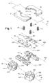
- This device comprises a housing 1 for example made of an insulating material, one or more modules, such as 21 and 22, each having a rocker member such as 210 and 220, and an actuating mechanism 3 of these tilting members.
- the module 21, or each of the modules 21 and 22, is typically constituted by an electrical switch in the preferred application of the invention.
- Each rocker member such as 210 and 220, is mounted oscillating between two positions around a main axis X0, fixed relative to the housing 1 and which are aligned in the modules 21 and 22 when using two modules.
- the actuating mechanism 3 comprises one or two control levers such as 31 and 32.
- Each of the control levers 31 and 32 is rotatably mounted about a proximal axis X1 substantially parallel to the main axis X0 fixed relative to the housing 1, and for example supported by the latter.
- each of the control levers 31 and 32 is kinematically connected to the rocker member 210 or rocker members 210 and 220 to cause the tilting.
- the actuating mechanism 3 further comprises one or more return levers such as 33 and 34 each of which is assigned to a corresponding control lever, such as 31 or 32.
- Each of the return levers 33 and 34 forms a kinematic connection between the control lever 31 or 32 corresponding, and the rocker members 210 and 220.
- Each of the return levers 33 and 34 is also rotatably mounted about a corresponding distal axis, such as X21 and X22, fixed relative to the housing 1 and substantially parallel to the main axis X0.
- Each of the control levers 31 and 32 is of the second or third type and comprises a bearing zone such as 310 or 320, selectively pressing the corresponding return lever, 33 or 34.
- Each of the return levers 33 and 34 is itself of the third type and comprises a corresponding bearing zone 330 or 340 selectively pressing the rocker member or bodies 210 and 220.
- each of the control levers 31 and 32 has an angular clearance smaller than that of the tilting it prints to the tilting member 210 or tilting members 210 and 220.
- control levers 31 and 32 are mounted symmetrically with respect to a plane of symmetry P passing through the main axis X0 and relative to which the return levers 33 and 34 are also mounted symmetrically, the distal axes X21 and X22 are therefore symmetrical to each other with respect to this plane P, as well as the axes of the control levers 31 and 32.
- control levers 31 and 32 may, alternatively, share the same axis X1 located in the plane of symmetry P, which thus passes through both the main axis X0 and this proximal axis X1 .
- Each distal axis X21 or X22 is typically separated from this plane of symmetry P by a distance greater than the distance separating the proximal axis X1 from the main axis X0.
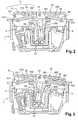
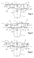
- Each of the control levers 31 and 32 is monostable and constantly recalled, by one or more springs such as R, to a rest position illustrated in FIGS. 2 and 4, and that it only leaves under the effect of a pressure. exercised by a user.
- Each of the tilting members 210 and 220 may be stable only in one of its two tilting positions, in which case the corresponding modules 21 and 22 are monostable.
- each of the tilting members 210 and 220 can also be stable in each of its two tilting positions, in which case the corresponding modules 21 and 22 are bistable.
- Each of these modules 21 and 22 is for example provided with at least three terminals, such as 211 to 213 and 221 to 223.
- the first terminal 211 of this module 21 is brought into contact with the second terminal 212, while the first terminal 211 of this module 21 is brought into contact with the third terminal 213 of the same module when the tilting member 210 is placed in its second tilting position.
- the first terminal 221 of this module 22 is brought into contact with the second terminal 222, while the first terminal 221 of this module 22 is contacting the third terminal 223 of the same module when the rocker member 220 is placed in its second tilting position.
- the device of the invention advantageously comprises a support 4 formed or arranged in the housing 1 and supporting the axis X21 or X22 of each return lever 33 or 34.
- Each return lever 33 or 34 may take the form of a pallet with a hinge edge 331 or 341 forms the corresponding axis X21 or X22 and runs along an edge of the housing 1.
- Each of these pallets is therefore provided with a support zone 330 or 340 selectively pressing on the rocking member or the rocking members 210 and 220 of one or more modules 21 and 22.
- each control lever 31 or 32 may take the form of a flap with a bearing zone 310 or 320, as illustrated in particular in Figure 1.
Landscapes
- Switches With Compound Operations (AREA)
- Mechanical Control Devices (AREA)
- Blinds (AREA)
- Arrangement Or Mounting Of Control Devices For Change-Speed Gearing (AREA)
- Rotary Switch, Piano Key Switch, And Lever Switch (AREA)
- Non-Deflectable Wheels, Steering Of Trailers, Or Other Steering (AREA)
- Forklifts And Lifting Vehicles (AREA)
- Rear-View Mirror Devices That Are Mounted On The Exterior Of The Vehicle (AREA)
Priority Applications (1)
| Application Number | Priority Date | Filing Date | Title |
|---|---|---|---|
| PL06290882T PL1732096T3 (pl) | 2005-06-07 | 2006-05-31 | Urządzenie sterujące z dźwignią wahliwą, o zmniejszonym wychyleniu kątowym |
Applications Claiming Priority (1)
| Application Number | Priority Date | Filing Date | Title |
|---|---|---|---|
| FR0505789A FR2886757B1 (fr) | 2005-06-07 | 2005-06-07 | Dispositif de commande a levier basculant, de debattement angulaire reduit |
Publications (2)
| Publication Number | Publication Date |
|---|---|
| EP1732096A1 true EP1732096A1 (de) | 2006-12-13 |
| EP1732096B1 EP1732096B1 (de) | 2007-12-26 |
Family
ID=35520985
Family Applications (1)
| Application Number | Title | Priority Date | Filing Date |
|---|---|---|---|
| EP06290882A Not-in-force EP1732096B1 (de) | 2005-06-07 | 2006-05-31 | Schwenkhebelsteuereinrichtung mit reduziertem Winkelbereich |
Country Status (8)
| Country | Link |
|---|---|
| EP (1) | EP1732096B1 (de) |
| CN (1) | CN1877482B (de) |
| AT (1) | ATE382187T1 (de) |
| DE (1) | DE602006000362T2 (de) |
| ES (1) | ES2299161T3 (de) |
| FR (1) | FR2886757B1 (de) |
| PL (1) | PL1732096T3 (de) |
| PT (1) | PT1732096E (de) |
Cited By (3)
| Publication number | Priority date | Publication date | Assignee | Title |
|---|---|---|---|---|
| IT201900025546A1 (it) * | 2019-12-24 | 2021-06-24 | Vimar Spa | Interruttore elettrico |
| EP4439609A1 (de) | 2023-03-31 | 2024-10-02 | Vimar S.p.A. | Elektrischer schalter |
| EP4439607A1 (de) * | 2023-03-31 | 2024-10-02 | Vimar S.p.A. | Elektrischer schalter |
Families Citing this family (1)
| Publication number | Priority date | Publication date | Assignee | Title |
|---|---|---|---|---|
| FR3078819B1 (fr) * | 2018-03-08 | 2020-03-20 | Legrand France | Manoeuvre synchronise d'un dispositif bistable depuis une multitude de manettes monostables |
Citations (3)
| Publication number | Priority date | Publication date | Assignee | Title |
|---|---|---|---|---|
| FR2667719A1 (fr) * | 1990-10-04 | 1992-04-10 | Legrand Sa | Interrupteur double. |
| US5285039A (en) * | 1991-09-18 | 1994-02-08 | Alps Electric Co., Ltd. | Seesaw type switch |
| EP1341200A2 (de) * | 2002-02-28 | 2003-09-03 | Alps Electric Co., Ltd. | Schaltervorrichtung |
-
2005
- 2005-06-07 FR FR0505789A patent/FR2886757B1/fr not_active Expired - Fee Related
-
2006
- 2006-05-31 PL PL06290882T patent/PL1732096T3/pl unknown
- 2006-05-31 DE DE602006000362T patent/DE602006000362T2/de active Active
- 2006-05-31 AT AT06290882T patent/ATE382187T1/de not_active IP Right Cessation
- 2006-05-31 EP EP06290882A patent/EP1732096B1/de not_active Not-in-force
- 2006-05-31 ES ES06290882T patent/ES2299161T3/es active Active
- 2006-05-31 PT PT06290882T patent/PT1732096E/pt unknown
- 2006-06-07 CN CN2006100831693A patent/CN1877482B/zh not_active Expired - Fee Related
Patent Citations (3)
| Publication number | Priority date | Publication date | Assignee | Title |
|---|---|---|---|---|
| FR2667719A1 (fr) * | 1990-10-04 | 1992-04-10 | Legrand Sa | Interrupteur double. |
| US5285039A (en) * | 1991-09-18 | 1994-02-08 | Alps Electric Co., Ltd. | Seesaw type switch |
| EP1341200A2 (de) * | 2002-02-28 | 2003-09-03 | Alps Electric Co., Ltd. | Schaltervorrichtung |
Cited By (4)
| Publication number | Priority date | Publication date | Assignee | Title |
|---|---|---|---|---|
| IT201900025546A1 (it) * | 2019-12-24 | 2021-06-24 | Vimar Spa | Interruttore elettrico |
| WO2021130721A1 (en) * | 2019-12-24 | 2021-07-01 | Vimar S.P.A. | Electrical switch |
| EP4439609A1 (de) | 2023-03-31 | 2024-10-02 | Vimar S.p.A. | Elektrischer schalter |
| EP4439607A1 (de) * | 2023-03-31 | 2024-10-02 | Vimar S.p.A. | Elektrischer schalter |
Also Published As
| Publication number | Publication date |
|---|---|
| FR2886757A1 (fr) | 2006-12-08 |
| PL1732096T3 (pl) | 2008-04-30 |
| DE602006000362D1 (de) | 2008-02-07 |
| CN1877482A (zh) | 2006-12-13 |
| CN1877482B (zh) | 2013-07-31 |
| PT1732096E (pt) | 2008-03-03 |
| EP1732096B1 (de) | 2007-12-26 |
| ATE382187T1 (de) | 2008-01-15 |
| FR2886757B1 (fr) | 2007-09-07 |
| ES2299161T3 (es) | 2008-05-16 |
| DE602006000362T2 (de) | 2008-12-11 |
Similar Documents
| Publication | Publication Date | Title |
|---|---|---|
| EP1732096B1 (de) | Schwenkhebelsteuereinrichtung mit reduziertem Winkelbereich | |
| FR2957187A1 (fr) | Commutateur electrique a effet tactile a double action | |
| FR2718280A1 (fr) | Commutateur à levier. | |
| EP2342728B1 (de) | Tastatur mit weitem tastenabstand und verbessertem berührungsgefühl | |
| FR3053523A1 (fr) | Commutateur electrique a positions multiples | |
| EP0919436B1 (de) | Unter dem Lenkrad angeordneter, elektrischer Steuerungsschalthebel | |
| EP1665316B1 (de) | Abschalteinrichtung für elektrischen strom mit vollständiger unterscheidung von zuständen | |
| EP0193440B1 (de) | Schutzschalter | |
| EP2581924B1 (de) | Vorrichtung zur Transkription einer mechanischen Position in einen elektrischen Zustand | |
| EP3975216B1 (de) | Teilesatz zur herstellung eines schalters | |
| EP1515352B1 (de) | Vorrichtung zur elektrischen Stromabschaltung mit einem translatorisch bewegbaren Kontakt | |
| EP0996959B1 (de) | Elektrischer leistungsschalter für elektrische anlagen mit niederwechselspannung | |
| FR2735609A1 (fr) | Mecanisme d'interrupteur | |
| EP1209029B1 (de) | Lenkstockschaltereinrichtung für Kraftfahrzeuge | |
| EP0403329A1 (de) | Schalter mit automatischer Auslösung, insbesondere Schutzschalter und Fehlerstromschutzschalter | |
| EP0194938B1 (de) | Parklicht- und Fahrrichtungsblinkschalteinrichtung für Kraftfahrzeuge | |
| EP1995749A2 (de) | Steuermechanismus über einen Kipphebel und multiple Konfigurationen und dessen Anwendung | |
| CH716204B1 (fr) | Combiné disjoncteur et interrupteur sectionneur. | |
| FR3000597A1 (fr) | Selecteur de commande. | |
| WO1994015348A1 (fr) | Systeme de commande d'inversion d'un moteur electrique | |
| FR2584231A1 (fr) | Commutateur electrique a bouton poussoir notamment pour equipement electrique de vehicule automobile | |
| CH693520A5 (fr) | Interrupteur de type push-push. | |
| FR2906928A1 (fr) | Commutateur electrique securise | |
| FR2818007A1 (fr) | Bloc auxiliaire a contact etanche | |
| FR2709863A1 (fr) | Disjoncteur à arbre de commutation rotatif. |
Legal Events
| Date | Code | Title | Description |
|---|---|---|---|
| PUAI | Public reference made under article 153(3) epc to a published international application that has entered the european phase |
Free format text: ORIGINAL CODE: 0009012 |
|
| AK | Designated contracting states |
Kind code of ref document: A1 Designated state(s): AT BE BG CH CY CZ DE DK EE ES FI FR GB GR HU IE IS IT LI LT LU LV MC NL PL PT RO SE SI SK TR |
|
| AX | Request for extension of the european patent |
Extension state: AL BA HR MK YU |
|
| 17P | Request for examination filed |
Effective date: 20070426 |
|
| GRAP | Despatch of communication of intention to grant a patent |
Free format text: ORIGINAL CODE: EPIDOSNIGR1 |
|
| AKX | Designation fees paid |
Designated state(s): AT BE BG CH CY CZ DE DK EE ES FI FR GB GR HU IE IS IT LI LT LU LV MC NL PL PT RO SE SI SK TR |
|
| GRAS | Grant fee paid |
Free format text: ORIGINAL CODE: EPIDOSNIGR3 |
|
| GRAA | (expected) grant |
Free format text: ORIGINAL CODE: 0009210 |
|
| AK | Designated contracting states |
Kind code of ref document: B1 Designated state(s): AT BE BG CH CY CZ DE DK EE ES FI FR GB GR HU IE IS IT LI LT LU LV MC NL PL PT RO SE SI SK TR |
|
| REG | Reference to a national code |
Ref country code: GB Ref legal event code: FG4D Free format text: NOT ENGLISH |
|
| REG | Reference to a national code |
Ref country code: IE Ref legal event code: FG4D Free format text: LANGUAGE OF EP DOCUMENT: FRENCH |
|
| REG | Reference to a national code |
Ref country code: CH Ref legal event code: EP |
|
| REF | Corresponds to: |
Ref document number: 602006000362 Country of ref document: DE Date of ref document: 20080207 Kind code of ref document: P |
|
| GBT | Gb: translation of ep patent filed (gb section 77(6)(a)/1977) |
Effective date: 20080131 |
|
| REG | Reference to a national code |
Ref country code: PT Ref legal event code: SC4A Free format text: AVAILABILITY OF NATIONAL TRANSLATION Effective date: 20080218 |
|
| REG | Reference to a national code |
Ref country code: GR Ref legal event code: EP Ref document number: 20080400689 Country of ref document: GR |
|
| PG25 | Lapsed in a contracting state [announced via postgrant information from national office to epo] |
Ref country code: SE Free format text: LAPSE BECAUSE OF FAILURE TO SUBMIT A TRANSLATION OF THE DESCRIPTION OR TO PAY THE FEE WITHIN THE PRESCRIBED TIME-LIMIT Effective date: 20080326 |
|
| REG | Reference to a national code |
Ref country code: PL Ref legal event code: T3 |
|
| REG | Reference to a national code |
Ref country code: ES Ref legal event code: FG2A Ref document number: 2299161 Country of ref document: ES Kind code of ref document: T3 |
|
| PG25 | Lapsed in a contracting state [announced via postgrant information from national office to epo] |
Ref country code: LV Free format text: LAPSE BECAUSE OF FAILURE TO SUBMIT A TRANSLATION OF THE DESCRIPTION OR TO PAY THE FEE WITHIN THE PRESCRIBED TIME-LIMIT Effective date: 20071226 Ref country code: FI Free format text: LAPSE BECAUSE OF FAILURE TO SUBMIT A TRANSLATION OF THE DESCRIPTION OR TO PAY THE FEE WITHIN THE PRESCRIBED TIME-LIMIT Effective date: 20071226 Ref country code: NL Free format text: LAPSE BECAUSE OF FAILURE TO SUBMIT A TRANSLATION OF THE DESCRIPTION OR TO PAY THE FEE WITHIN THE PRESCRIBED TIME-LIMIT Effective date: 20071226 Ref country code: SI Free format text: LAPSE BECAUSE OF FAILURE TO SUBMIT A TRANSLATION OF THE DESCRIPTION OR TO PAY THE FEE WITHIN THE PRESCRIBED TIME-LIMIT Effective date: 20071226 |
|
| NLV1 | Nl: lapsed or annulled due to failure to fulfill the requirements of art. 29p and 29m of the patents act | ||
| PG25 | Lapsed in a contracting state [announced via postgrant information from national office to epo] |
Ref country code: LT Free format text: LAPSE BECAUSE OF FAILURE TO SUBMIT A TRANSLATION OF THE DESCRIPTION OR TO PAY THE FEE WITHIN THE PRESCRIBED TIME-LIMIT Effective date: 20071226 Ref country code: CZ Free format text: LAPSE BECAUSE OF FAILURE TO SUBMIT A TRANSLATION OF THE DESCRIPTION OR TO PAY THE FEE WITHIN THE PRESCRIBED TIME-LIMIT Effective date: 20071226 Ref country code: IS Free format text: LAPSE BECAUSE OF FAILURE TO SUBMIT A TRANSLATION OF THE DESCRIPTION OR TO PAY THE FEE WITHIN THE PRESCRIBED TIME-LIMIT Effective date: 20080426 |
|
| PG25 | Lapsed in a contracting state [announced via postgrant information from national office to epo] |
Ref country code: RO Free format text: LAPSE BECAUSE OF FAILURE TO SUBMIT A TRANSLATION OF THE DESCRIPTION OR TO PAY THE FEE WITHIN THE PRESCRIBED TIME-LIMIT Effective date: 20071226 Ref country code: SK Free format text: LAPSE BECAUSE OF FAILURE TO SUBMIT A TRANSLATION OF THE DESCRIPTION OR TO PAY THE FEE WITHIN THE PRESCRIBED TIME-LIMIT Effective date: 20071226 |
|
| REG | Reference to a national code |
Ref country code: IE Ref legal event code: FD4D |
|
| PG25 | Lapsed in a contracting state [announced via postgrant information from national office to epo] |
Ref country code: IE Free format text: LAPSE BECAUSE OF FAILURE TO SUBMIT A TRANSLATION OF THE DESCRIPTION OR TO PAY THE FEE WITHIN THE PRESCRIBED TIME-LIMIT Effective date: 20071226 Ref country code: DK Free format text: LAPSE BECAUSE OF FAILURE TO SUBMIT A TRANSLATION OF THE DESCRIPTION OR TO PAY THE FEE WITHIN THE PRESCRIBED TIME-LIMIT Effective date: 20071226 |
|
| PLBE | No opposition filed within time limit |
Free format text: ORIGINAL CODE: 0009261 |
|
| STAA | Information on the status of an ep patent application or granted ep patent |
Free format text: STATUS: NO OPPOSITION FILED WITHIN TIME LIMIT |
|
| 26N | No opposition filed |
Effective date: 20080929 |
|
| PG25 | Lapsed in a contracting state [announced via postgrant information from national office to epo] |
Ref country code: MC Free format text: LAPSE BECAUSE OF NON-PAYMENT OF DUE FEES Effective date: 20080531 |
|
| PG25 | Lapsed in a contracting state [announced via postgrant information from national office to epo] |
Ref country code: EE Free format text: LAPSE BECAUSE OF FAILURE TO SUBMIT A TRANSLATION OF THE DESCRIPTION OR TO PAY THE FEE WITHIN THE PRESCRIBED TIME-LIMIT Effective date: 20071226 Ref country code: BG Free format text: LAPSE BECAUSE OF FAILURE TO SUBMIT A TRANSLATION OF THE DESCRIPTION OR TO PAY THE FEE WITHIN THE PRESCRIBED TIME-LIMIT Effective date: 20080326 |
|
| REG | Reference to a national code |
Ref country code: HU Ref legal event code: AG4A Ref document number: E004827 Country of ref document: HU |
|
| PG25 | Lapsed in a contracting state [announced via postgrant information from national office to epo] |
Ref country code: CY Free format text: LAPSE BECAUSE OF FAILURE TO SUBMIT A TRANSLATION OF THE DESCRIPTION OR TO PAY THE FEE WITHIN THE PRESCRIBED TIME-LIMIT Effective date: 20071226 |
|
| PGFP | Annual fee paid to national office [announced via postgrant information from national office to epo] |
Ref country code: AT Payment date: 20090529 Year of fee payment: 4 Ref country code: PL Payment date: 20090604 Year of fee payment: 4 Ref country code: PT Payment date: 20090520 Year of fee payment: 4 |
|
| PGFP | Annual fee paid to national office [announced via postgrant information from national office to epo] |
Ref country code: BE Payment date: 20090518 Year of fee payment: 4 |
|
| PGFP | Annual fee paid to national office [announced via postgrant information from national office to epo] |
Ref country code: HU Payment date: 20090602 Year of fee payment: 4 |
|
| PG25 | Lapsed in a contracting state [announced via postgrant information from national office to epo] |
Ref country code: LU Free format text: LAPSE BECAUSE OF NON-PAYMENT OF DUE FEES Effective date: 20080531 |
|
| BERE | Be: lapsed |
Owner name: LEGRAND FRANCE Effective date: 20100531 Owner name: LEGRAND SNC Effective date: 20100531 |
|
| REG | Reference to a national code |
Ref country code: PT Ref legal event code: MM4A Free format text: LAPSE DUE TO NON-PAYMENT OF FEES Effective date: 20101130 |
|
| REG | Reference to a national code |
Ref country code: CH Ref legal event code: PL |
|
| GBPC | Gb: european patent ceased through non-payment of renewal fee |
Effective date: 20100531 |
|
| PG25 | Lapsed in a contracting state [announced via postgrant information from national office to epo] |
Ref country code: LI Free format text: LAPSE BECAUSE OF NON-PAYMENT OF DUE FEES Effective date: 20100531 Ref country code: IT Free format text: LAPSE BECAUSE OF FAILURE TO SUBMIT A TRANSLATION OF THE DESCRIPTION OR TO PAY THE FEE WITHIN THE PRESCRIBED TIME-LIMIT Effective date: 20071226 Ref country code: CH Free format text: LAPSE BECAUSE OF NON-PAYMENT OF DUE FEES Effective date: 20100531 Ref country code: HU Free format text: LAPSE BECAUSE OF NON-PAYMENT OF DUE FEES Effective date: 20100601 Ref country code: PT Free format text: LAPSE BECAUSE OF NON-PAYMENT OF DUE FEES Effective date: 20101130 |
|
| PG25 | Lapsed in a contracting state [announced via postgrant information from national office to epo] |
Ref country code: GR Free format text: LAPSE BECAUSE OF NON-PAYMENT OF DUE FEES Effective date: 20101202 Ref country code: BE Free format text: LAPSE BECAUSE OF NON-PAYMENT OF DUE FEES Effective date: 20100531 |
|
| PG25 | Lapsed in a contracting state [announced via postgrant information from national office to epo] |
Ref country code: GB Free format text: LAPSE BECAUSE OF NON-PAYMENT OF DUE FEES Effective date: 20100531 |
|
| REG | Reference to a national code |
Ref country code: AT Ref legal event code: MM01 Ref document number: 382187 Country of ref document: AT Kind code of ref document: T Effective date: 20110531 |
|
| PG25 | Lapsed in a contracting state [announced via postgrant information from national office to epo] |
Ref country code: AT Free format text: LAPSE BECAUSE OF NON-PAYMENT OF DUE FEES Effective date: 20110531 Ref country code: PL Free format text: LAPSE BECAUSE OF NON-PAYMENT OF DUE FEES Effective date: 20100531 |
|
| REG | Reference to a national code |
Ref country code: PL Ref legal event code: LAPE |
|
| REG | Reference to a national code |
Ref country code: FR Ref legal event code: PLFP Year of fee payment: 11 |
|
| REG | Reference to a national code |
Ref country code: FR Ref legal event code: PLFP Year of fee payment: 12 |
|
| REG | Reference to a national code |
Ref country code: FR Ref legal event code: PLFP Year of fee payment: 13 |
|
| PGFP | Annual fee paid to national office [announced via postgrant information from national office to epo] |
Ref country code: TR Payment date: 20190211 Year of fee payment: 14 |
|
| PGFP | Annual fee paid to national office [announced via postgrant information from national office to epo] |
Ref country code: FR Payment date: 20200527 Year of fee payment: 15 Ref country code: ES Payment date: 20200618 Year of fee payment: 15 Ref country code: DE Payment date: 20200528 Year of fee payment: 15 |
|
| REG | Reference to a national code |
Ref country code: DE Ref legal event code: R119 Ref document number: 602006000362 Country of ref document: DE |
|
| PG25 | Lapsed in a contracting state [announced via postgrant information from national office to epo] |
Ref country code: DE Free format text: LAPSE BECAUSE OF NON-PAYMENT OF DUE FEES Effective date: 20211201 |
|
| PG25 | Lapsed in a contracting state [announced via postgrant information from national office to epo] |
Ref country code: FR Free format text: LAPSE BECAUSE OF NON-PAYMENT OF DUE FEES Effective date: 20210531 |
|
| PG25 | Lapsed in a contracting state [announced via postgrant information from national office to epo] |
Ref country code: TR Free format text: LAPSE BECAUSE OF NON-PAYMENT OF DUE FEES Effective date: 20200531 |
|
| REG | Reference to a national code |
Ref country code: ES Ref legal event code: FD2A Effective date: 20220804 |
|
| PG25 | Lapsed in a contracting state [announced via postgrant information from national office to epo] |
Ref country code: ES Free format text: LAPSE BECAUSE OF NON-PAYMENT OF DUE FEES Effective date: 20210601 |