EP1732099A2 - Relais électromagnétique - Google Patents
Relais électromagnétique Download PDFInfo
- Publication number
- EP1732099A2 EP1732099A2 EP06009868A EP06009868A EP1732099A2 EP 1732099 A2 EP1732099 A2 EP 1732099A2 EP 06009868 A EP06009868 A EP 06009868A EP 06009868 A EP06009868 A EP 06009868A EP 1732099 A2 EP1732099 A2 EP 1732099A2
- Authority
- EP
- European Patent Office
- Prior art keywords
- base
- contact
- electromagnetic relay
- movable
- mechanisms
- Prior art date
- Legal status (The legal status is an assumption and is not a legal conclusion. Google has not performed a legal analysis and makes no representation as to the accuracy of the status listed.)
- Withdrawn
Links
Images



Classifications
-
- H—ELECTRICITY
- H01—ELECTRIC ELEMENTS
- H01H—ELECTRIC SWITCHES; RELAYS; SELECTORS; EMERGENCY PROTECTIVE DEVICES
- H01H50/00—Details of electromagnetic relays
- H01H50/64—Driving arrangements between movable part of magnetic circuit and contact
- H01H50/641—Driving arrangements between movable part of magnetic circuit and contact intermediate part performing a rectilinear movement
- H01H50/642—Driving arrangements between movable part of magnetic circuit and contact intermediate part performing a rectilinear movement intermediate part being generally a slide plate, e.g. a card
-
- H—ELECTRICITY
- H01—ELECTRIC ELEMENTS
- H01H—ELECTRIC SWITCHES; RELAYS; SELECTORS; EMERGENCY PROTECTIVE DEVICES
- H01H50/00—Details of electromagnetic relays
- H01H50/16—Magnetic circuit arrangements
- H01H50/18—Movable parts of magnetic circuits, e.g. armature
- H01H50/24—Parts rotatable or rockable outside coil
-
- H—ELECTRICITY
- H01—ELECTRIC ELEMENTS
- H01H—ELECTRIC SWITCHES; RELAYS; SELECTORS; EMERGENCY PROTECTIVE DEVICES
- H01H51/00—Electromagnetic relays
- H01H51/22—Polarised relays
- H01H51/2272—Polarised relays comprising rockable armature, rocking movement around central axis parallel to the main plane of the armature
-
- H—ELECTRICITY
- H01—ELECTRIC ELEMENTS
- H01H—ELECTRIC SWITCHES; RELAYS; SELECTORS; EMERGENCY PROTECTIVE DEVICES
- H01H50/00—Details of electromagnetic relays
- H01H50/02—Bases; Casings; Covers
- H01H2050/028—Means to improve the overall withstanding voltage, e.g. creepage distances
-
- H—ELECTRICITY
- H01—ELECTRIC ELEMENTS
- H01H—ELECTRIC SWITCHES; RELAYS; SELECTORS; EMERGENCY PROTECTIVE DEVICES
- H01H50/00—Details of electromagnetic relays
- H01H50/02—Bases; Casings; Covers
- H01H50/04—Mounting complete relay or separate parts of relay on a base or inside a case
- H01H50/041—Details concerning assembly of relays
- H01H50/043—Details particular to miniaturised relays
- H01H2050/044—Special measures to minimise the height of the relay
-
- H—ELECTRICITY
- H01—ELECTRIC ELEMENTS
- H01H—ELECTRIC SWITCHES; RELAYS; SELECTORS; EMERGENCY PROTECTIVE DEVICES
- H01H50/00—Details of electromagnetic relays
- H01H50/02—Bases; Casings; Covers
- H01H50/023—Details concerning sealing, e.g. sealing casing with resin
-
- H—ELECTRICITY
- H01—ELECTRIC ELEMENTS
- H01H—ELECTRIC SWITCHES; RELAYS; SELECTORS; EMERGENCY PROTECTIVE DEVICES
- H01H50/00—Details of electromagnetic relays
- H01H50/02—Bases; Casings; Covers
- H01H50/026—Details concerning isolation between driving and switching circuit
-
- H—ELECTRICITY
- H01—ELECTRIC ELEMENTS
- H01H—ELECTRIC SWITCHES; RELAYS; SELECTORS; EMERGENCY PROTECTIVE DEVICES
- H01H50/00—Details of electromagnetic relays
- H01H50/02—Bases; Casings; Covers
- H01H50/04—Mounting complete relay or separate parts of relay on a base or inside a case
- H01H50/041—Details concerning assembly of relays
- H01H50/043—Details particular to miniaturised relays
-
- H—ELECTRICITY
- H01—ELECTRIC ELEMENTS
- H01H—ELECTRIC SWITCHES; RELAYS; SELECTORS; EMERGENCY PROTECTIVE DEVICES
- H01H50/00—Details of electromagnetic relays
- H01H50/14—Terminal arrangements
Definitions
- the present invention relates to a multipolar electromagnetic relay including plural contact mechanisms.
- Japanese Patent Application Laid-Open No. 2000-285782 discloses a multipolar electromagnetic relay, in which an electromagnetic block and a movable block are assembled in a longitudinal attitude on a base formed by resin molding, plural contact mechanisms are laterally provided in parallel in two rows while sandwiching a partition, and terminals extended from the respective contact mechanisms are projected from a bottom surface of the base.
- an object of the present invention is to provide an electromagnetic relay which can be flattened in shape to perform a low profile mounting, downsized for the number of electrodes, and excellent for assembling the internal components.
- the present invention is configured as follows.
- An electromagnetic relay of the present invention in which an electromagnetic block having an iron core around which a coil being wound; a movable block having an iron piece which is attracted to and separated from a magnetic pole portion of the electromagnetic block, the movable block is normally and reversely rotated by magnetic excitation and demagnetization of the electromagnetic block; a moving body engaging the movable block to be reciprocally moved in a linear direction according to the normal and reverse rotations; and plural contact mechanisms in which switching is operated by the movement of the moving body are assembled to a base, wherein the electromagnetic block and the movable block are arranged such that a rotating shaft of the movable block is vertically located with respect to a bottom surface of the base, a fixed contact piece and a movable contact piece in the plural contact mechanisms are arranged such that longitudinal directions of the fixed contact piece and the movable contact piece are parallel to the bottom surface of the base, the plural contact mechanisms are arranged in parallel with the moving direction of the moving body while alternately arranged in upper and lower stages along the moving direction of the moving body,
- the electromagnetic block, the movable block, the upper and lower contact mechanism groups, and the moving body are assembled in an inclination attitude with respect to the base. Therefore, the low-profile electromagnetic relay can be realized, and the electromagnetic relay can be mounted on a board without being bulky.
- the contact mechanisms are arranged in parallel in the upper and lower stages, so that the compact electromagnetic relay can be formed in the moving direction when compared with the case where all the same number of contact mechanisms is arranged in parallel in the one stage. Because each component can be assembled from above the base, it is not necessary that the attitude of the base be changed during the assemble process.
- the plural contact mechanisms are alternately arranged in the upper and lower stage along the moving direction of the moving body, namely, the upper contact mechanism and the lower contact mechanism are alternately arranged in the moving direction. Therefore, the insulating properties can be improved between the adjacent upper and lower contact mechanisms while the downsizing is achieved in the moving direction.
- base ends of the fixed contact piece and movable contact piece constituting the contact mechanism are coupled to and supported by a support plate to which the terminal is continuously provided, and an attachment groove into which the support plate is press-fitted is formed in the base.
- the support plate to which each contact is coupled can be assembled to the attachment groove of the base by press-fitting the support plate from above.
- a partition located between the contact mechanisms is vertically provided in the base, the contact mechanisms being arranged in parallel to the moving direction.
- the insulating properties can be enhanced between the adjacent contact mechanisms arranged in parallel along the moving direction of the moving body.
- the attachment groove is formed in a wall portion vertically provided in the base, the support plate of the contact mechanism arranged in the upper stage being press-fitted into the attachment groove, and the wall portion is continuously provided to the partition.
- the wall portion supporting the contact mechanism and the insulating partition strengthen each other, so that the insulating properties and mechanical durability are effectively enhanced.
- the partition located between the contact mechanisms is provided inside an enclosure fitted over the base, the contact mechanism being arranged in parallel to the moving direction.
- the insulation between the adjacent contact mechanisms is achieved by combining the partition of the base and the partition of the enclosure, so that the insulating properties can further be improved.
- the partition of the enclosure exerts a function of a reinforcing rib to enhance rigidity of the enclosure in itself.
- the support plate is formed in a shape in which a part of a support plate material is cut, and the support plate material being punched in the same requirement.
- the many contact mechanisms can be formed by one kind of the fixed contact piece, one kind of the movable contact piece, and one kind of the support plate material. Therefore, the number of kinds of component punching dies can be decreased to achieve cost reduction.
- a bearing hole is made in a bottom portion of the base while vertically penetrating the bottom portion, the rotating shaft of the movable block being fitted in the bearing hole and supported by the bearing hole, and a boss portion is projected from the bottom surface of the base, the boss portion sealing an opening end of the bearing hole.
- the bearing hole is made so as to penetrate the base. Therefore, when compared with the case where the bearing hole is made in the bore hole which is not opened to the bottom surface of the base, there is no limitation to the method or procedure of inserting the rotating shaft.
- the intrusion of dust and moisture into the electromagnetic relay can be securely prevented by sealing the bearing hole after the assembly, so that reliability can be improved in the contact switching operation.
- the present invention can provide the electromagnetic relay which can be flattened in shape to perform a low profile mounting, downsized for the number of electrodes, and excellent for assembling the internal components.
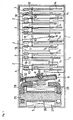
- Fig. 1 shows a plan view of the whole of an electromagnetic relay with an enclosure detached
- Fig. 1 shows a transverse plan view of an electromagnetic relay according to the invention
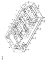
- Fig. 2 shows a perspective view of an internal structure of the electromagnetic relay
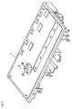
- Fig. 3 shows a perspective view in which a base and a contact mechanism are taken apart.
- the electromagnetic relay mainly includes a base 1, multipolar contact mechanisms 2 and 3, a card 4, an electromagnetic block 5, a card driving movable block 6, and an enclosure 7.
- the base 1 is molded by a resin material.
- the base 1 is long in a lateral direction and narrow in a cross direction.
- the contact mechanisms 2 and 3 are assembled to the base 1 in upper and lower stages.
- the card 4 is a contact switching moving body which is guided and supported on a rear side of the base 1 (upper side in Fig. 1) while being linearly reciprocally movable in the lateral direction.
- the electromagnetic block 5 is fixed to a side-end portion (left-end portion in Fig. 1) of the base 1.
- the movable block 6 is arranged so as to face the electromagnetic block 5, and the movable block 6 is rotatably supported about a fulcrum p which is vertically provided with respect to the base 1.
- the enclosure 7 is fitted over the base 1 from above the base 1. Detailed structures of the components will be described below. In the following description, the upper side in Fig. 1 is referred to as rear side, and the lower side is referred to as front side.
- the electromagnetic block 5 and the movable block 6 are arranged in an inclination attitude with respect to the base 1 such that a virtual axis line of a rotating shaft about the fulcrum p of the movable block 6 extends in the vertical direction with respect to a bottom surface of the base 1 as shown in Fig. 3.
- Contact pieces 10, 11, 12, and 13 constituting the contact mechanisms 2 and 3 are also arranged in the inclination attitude with respect to the base 1 such that a longitudinal directions of the contact pieces 10, 11, 12, and 13 (vertical direction in Fig. 1) are parallel to the bottom surface of the base 1.
- the contact mechanisms 2 and 3 are arranged in parallel along the lateral direction (moving direction of card 4), and the contact mechanisms 2 and 3 are alternately arranged along the lateral direction so as to be separated in the upper and lower stages.
- the three-pole contact mechanisms 2 are laterally arranged in parallel.
- the fixed contact piece 10 made of a thick plate material and the movable contact piece 11 made of a spring plate material are arranged in the lateral direction so as to face each other.
- the left-end contact mechanism 2 constitutes a set of normally closed circuits
- the central and right-end contact mechanisms 2 constitute two sets of normally opened circuits.
- the three-pole contact mechanisms 3 are laterally arranged in parallel.
- the fixed contact piece 12 and the movable contact piece 13 are arranged in the lateral direction so as to face each other.
- the contact mechanisms 2 constitute three sets of normally closed circuits.
- each of front-side base-end portions are fixed in a caulking manner to a support plate 14 made of the thick plate material.
- the contact pieces 10, 11, 12, and 13 are cantilevered toward the rear side.
- Each support plate 14 is press-fitted downward into an attachment groove 15 formed in the base 1.
- Terminals 14a and 14b extending from the support plate 14 are projected in two rows back and forth from a lower surface of the base 1 while piercing through the base 1.
- the support plate 14 of each of the contact mechanisms 2 and 3 is formed by cutting a part of a common support plate material 16 shown in Fig. 6. That is, the support plate material 16 is punched in a shape which includes a pair of long terminals 14a and 14b and a contact piece supporting caulking hole 17. The terminals 14a and 14b are located on the front and rear sides respectively. As shown in Figs. 7 and 8, the support plate 14 of the fixed contact piece 10 in the upper contact mechanism 2 is formed in the shape in which the rear-side terminal 14b is cut, and the support plate 14 of the movable contact piece 11 in the upper contact mechanism 2 is formed in the shape in which the rear-side terminal 14b is laterally bent while the front-side terminal 14a is cut.
- the support plate 14 of the fixed contact piece 12 in the lower contact mechanism 3 is formed in the shape in which the front-side terminal 14 is shortly cut while the rear-side terminal 14b is cut
- the support plate 14 of the movable contact piece 13 in the lower contact mechanism 3 is formed in the shape in which the rear-side terminal 14b is laterally bent and shortly cut while the front-side terminal 14a is cut.
- the upper contact mechanism 2 and the lower contact mechanism 3 are laterally arranged such that the positions of the mechanisms 2 and 3 are alternately shifted. Therefore, the insulation is satisfied between the adjacent contact mechanisms 2 and 3 while the downsizing of the electromagnetic relay is achieved in the lateral direction, and the contact mechanisms 2 and 3 can be assembled to the base 1 from above without obstructing each other.
- partitions 18 are vertically provided at appropriate positions of the base 1 to establish the insulation between the contact mechanisms 2 and 3.
- partitions 19 are also provided at appropriate positions in the enclosure 7 formed by resin molding.
- Fig. 10 which is a transverse sectional view of the electromagnetic relay with the enclosure 7 attached, the adjacent contact mechanisms 2 and 3 are partitioned by the partitions 18 and 19 to enhance the insulating properties.
- the attachment groove 15 of the support plate 14 in the upper contact mechanism 2 is formed in a longitudinal wall portion 20 vertically provided from the base 1.
- the longitudinal wall portion 20 and the partition 18 are continuously provided to strengthen each other.
- the card 4 is supported in the rear-side end portion of the partition 18 while being linearly slidable in the lateral direction. Idle ends of the movable contact pieces 11 and 13 are latched and supported in the contact mechanisms 2 and 3 respectively. The movable contact pieces 11 and 13 are laterally displaced to switch the contacts by the laterally reciprocal movement of the card 4. An idle end of a return spring 21 is latched in the card 4, and the return spring 21 is press-fitted in the base 1 while cantilevered toward the rear side. Return force toward the direction (leftward in Fig. 1) in which the electromagnetic block 5 is always imparted to the card 4 by elastic force of the return spring 21.
- a coil 27 is wound around a resin bobbin 26 fitted over an iron core 25, and magnetic-pole yokes 28 are coupled to both ends of the iron core 25 by the caulking.
- the movable block 6 is arranged so as to face a bent end portion of each yoke 28.
- a pair of terminals 29 connected to the coil 27 is projected from the lower surface of the base 1.
- the upper portion of the movable block 6 is rotated counterclockwise.
- the upper portion of the movable block 6 is rotated clockwise, which slidably moves the card 4 rightward in Fig. 1 to switch the upper and lower contact mechanisms 2 and 3.
- the movable block 6 includes a block main body 31, an iron piece 32, a rectangular block-shape permanent magnet 33, magnetic shielding plates 34, and a metal fulcrum shaft 35.
- the block main body 31 is molded by a resin material.
- the iron piece 32 formed by a thick iron plate is fitted over the front surface of the block main body 31.
- the permanent magnet 33 is attracted and fixed to the center of the front surface of the iron piece 32.
- the magnetic shielding plates 34 are attached to the upper and lower portion of the front surface of the iron piece 32, and the magnetic shielding plate 34 is made of a non-magnetic metal.
- the metal fulcrum shaft 35 is vertically inserted into the block main body 31.
- the both ends projected from the upper and lower surface of the movable block 6 are rotatably fitted in and supported by a bearing hole 37 and a bearing hole 38 respectively.
- the bearing hole 37 penetrates through a bearing portion 36 extending in the upper portion of the base 1, and the bearing hole 38 penetrates the bottom portion of the base 1.
- a boss portion 39 surrounding the bearing hole 38 is projected from the bottom surface of the base. After the internal components are assembled, the boss portion 39 is heated and melted to seal the bearing hole 38, which prevents dust and moisture from intruding into the inside through the bearing portion 36.
- the bearing hole 38 on the bottom side of the base 1 can be made in a bore hole which is not opened in the bottom surface. In this case, the thermal sealing boss portion 39 is not required.
Landscapes
- Physics & Mathematics (AREA)
- Electromagnetism (AREA)
- Electromagnets (AREA)
- Switch Cases, Indication, And Locking (AREA)
- Contacts (AREA)
- Coupling Device And Connection With Printed Circuit (AREA)
Applications Claiming Priority (1)
| Application Number | Priority Date | Filing Date | Title |
|---|---|---|---|
| JP2005166704A JP4424260B2 (ja) | 2005-06-07 | 2005-06-07 | 電磁リレー |
Publications (2)
| Publication Number | Publication Date |
|---|---|
| EP1732099A2 true EP1732099A2 (fr) | 2006-12-13 |
| EP1732099A3 EP1732099A3 (fr) | 2009-03-04 |
Family
ID=36992511
Family Applications (1)
| Application Number | Title | Priority Date | Filing Date |
|---|---|---|---|
| EP06009868A Withdrawn EP1732099A3 (fr) | 2005-06-07 | 2006-05-12 | Relais électromagnétique |
Country Status (5)
| Country | Link |
|---|---|
| US (1) | US7504915B2 (fr) |
| EP (1) | EP1732099A3 (fr) |
| JP (1) | JP4424260B2 (fr) |
| KR (1) | KR100761209B1 (fr) |
| CN (1) | CN100543902C (fr) |
Cited By (4)
| Publication number | Priority date | Publication date | Assignee | Title |
|---|---|---|---|---|
| US8222981B1 (en) | 2011-01-18 | 2012-07-17 | Tyco Electronics Corporation | Electrical switching device |
| EP2477204A1 (fr) * | 2011-01-18 | 2012-07-18 | Tyco Electronics Corporation | Dispositif de commutation électrique |
| EP2645399A4 (fr) * | 2010-11-08 | 2014-10-22 | Panasonic Corp | Relais électromagnétique |
| EP3113204A4 (fr) * | 2014-02-24 | 2017-09-27 | Omron Corporation | Relais électromagnétique |
Families Citing this family (33)
| Publication number | Priority date | Publication date | Assignee | Title |
|---|---|---|---|---|
| JP4730108B2 (ja) * | 2006-01-23 | 2011-07-20 | オムロン株式会社 | 電磁リレー |
| US7659800B2 (en) * | 2007-08-01 | 2010-02-09 | Philipp Gruner | Electromagnetic relay assembly |
| US7710224B2 (en) * | 2007-08-01 | 2010-05-04 | Clodi, L.L.C. | Electromagnetic relay assembly |
| US7889032B2 (en) * | 2008-07-16 | 2011-02-15 | Tyco Electronics Corporation | Electromagnetic relay |
| JP5349618B2 (ja) * | 2009-02-04 | 2013-11-20 | クロディ エルエルシー | 電磁リレーアセンブリ |
| WO2010150712A1 (fr) * | 2009-06-23 | 2010-12-29 | パナソニック電工株式会社 | Relais électromagnétique |
| JP2011228066A (ja) * | 2010-04-16 | 2011-11-10 | Nagaoka Univ Of Technology | 継電器、制御回路及び制御回路の制御方法 |
| US8330564B2 (en) * | 2010-05-04 | 2012-12-11 | Tyco Electronics Corporation | Switching devices configured to control magnetic fields to maintain an electrical connection |
| CN102024622B (zh) * | 2010-07-27 | 2013-06-26 | 广东格兰仕集团有限公司 | 继电器弹片与插片的固定方式 |
| JP5624431B2 (ja) * | 2010-11-08 | 2014-11-12 | パナソニック株式会社 | 電磁リレー |
| US8514040B2 (en) | 2011-02-11 | 2013-08-20 | Clodi, L.L.C. | Bi-stable electromagnetic relay with x-drive motor |
| JP4883232B1 (ja) * | 2011-03-14 | 2012-02-22 | オムロン株式会社 | 電磁継電器 |
| JP5085754B2 (ja) * | 2011-03-14 | 2012-11-28 | オムロン株式会社 | 電磁継電器 |
| CN103339705B (zh) * | 2011-03-14 | 2017-02-15 | 欧姆龙株式会社 | 电磁继电器 |
| JP6025414B2 (ja) * | 2011-09-30 | 2016-11-16 | 富士通コンポーネント株式会社 | 電磁継電器 |
| EP2761640B1 (fr) * | 2011-09-30 | 2016-08-10 | Telepath Networks, Inc. | Structures de dispositifs de commutation intégrés multiples |
| JP6168785B2 (ja) * | 2012-03-30 | 2017-07-26 | 富士通コンポーネント株式会社 | 有極電磁継電器 |
| DE102012017157A1 (de) * | 2012-08-30 | 2014-03-06 | Hengstler Gmbh | Relais mit modifizierter Kraft-Weg-Kennlinie |
| KR101917885B1 (ko) * | 2012-09-26 | 2018-11-13 | 현대일렉트릭앤에너지시스템(주) | 전자접촉기 |
| JP6043173B2 (ja) * | 2012-12-07 | 2016-12-14 | 富士通コンポーネント株式会社 | 電磁継電器 |
| JP6325278B2 (ja) * | 2014-02-19 | 2018-05-16 | 富士通コンポーネント株式会社 | 電磁継電器 |
| CN104157516A (zh) * | 2014-08-14 | 2014-11-19 | 哈尔滨工业大学 | 一种适用于双磁钢差动式继电器的推动器组及该推动器组的使用方法 |
| JP6590314B2 (ja) * | 2015-09-15 | 2019-10-16 | パナソニックIpマネジメント株式会社 | 固定接点素材および当該固定接点素材を用いて形成された固定接点部を備える電磁リレー |
| JP2017201593A (ja) * | 2016-05-02 | 2017-11-09 | 富士通コンポーネント株式会社 | 電磁継電器 |
| CN111295729B (zh) | 2017-11-01 | 2022-12-06 | 松下知识产权经营株式会社 | 电磁继电器和电磁装置 |
| CN107895676B (zh) * | 2017-12-15 | 2020-11-20 | 中艺银舟新能源汽车(北京)有限公司 | 多触头电极集成高稳定磁保持继电器 |
| CN108281327B (zh) * | 2018-02-08 | 2023-12-08 | 浙江格蕾特电器股份有限公司 | 多组双向控制继电器及其组装方法 |
| JP6973200B2 (ja) * | 2018-03-13 | 2021-11-24 | オムロン株式会社 | 接点開閉装置 |
| CN108962686B (zh) * | 2018-08-08 | 2024-08-09 | 漳州宏发电声有限公司 | 一种用于双电源切换的电磁继电器 |
| CH716470A1 (de) * | 2019-07-30 | 2021-02-15 | Elesta Gmbh Ostfildern De Zweigniederlassung Bad Ragaz | Doppelanker-Relais. |
| JP7543743B2 (ja) * | 2020-07-10 | 2024-09-03 | オムロン株式会社 | 電磁継電器 |
| JP7647199B2 (ja) * | 2021-03-15 | 2025-03-18 | オムロン株式会社 | 電磁継電器 |
| CN117352333A (zh) * | 2022-06-28 | 2024-01-05 | 泰科电子(上海)有限公司 | 电磁继电器 |
Family Cites Families (20)
| Publication number | Priority date | Publication date | Assignee | Title |
|---|---|---|---|---|
| DE2218494B1 (de) * | 1972-04-17 | 1973-10-11 | Siemens Ag, 1000 Berlin U. 8000 Muenchen | Elektromagnetisches Relais |
| DE2723430C2 (de) * | 1977-05-24 | 1984-04-26 | Siemens AG, 1000 Berlin und 8000 München | Elektromagnetisches Relais |
| DE3006948A1 (de) * | 1980-02-25 | 1981-09-10 | Siemens AG, 1000 Berlin und 8000 München | Polarisiertes magnetsystem |
| JPS57168152U (fr) * | 1981-04-17 | 1982-10-22 | ||
| DE3220985A1 (de) * | 1982-06-03 | 1983-12-08 | Siemens AG, 1000 Berlin und 8000 München | Elektromagnetisches drehankerrelais |
| JP2584398B2 (ja) * | 1992-12-07 | 1997-02-26 | 日本ヘンクストラ株式会社 | 電磁継電器 |
| DE4300594A1 (de) * | 1993-01-13 | 1994-07-14 | Hengstler Bauelemente | Sicherheitsrelais mit zwangsgeführtem Kontaktsatz und monostabilem Antrieb |
| JP3333898B2 (ja) | 1996-07-03 | 2002-10-15 | 富士電機株式会社 | 電磁接触器 |
| KR100186376B1 (ko) * | 1996-11-15 | 1999-05-15 | 구자홍 | 진공전자접촉기의 개폐용 보조스위치 |
| US6025766A (en) * | 1997-04-11 | 2000-02-15 | Siemens Energy & Automation, Inc. | Trip mechanism for an overload relay |
| EP0938119A1 (fr) * | 1998-02-18 | 1999-08-25 | ELESTA relays GmbH | Relais |
| DE19847831C2 (de) * | 1998-10-16 | 2002-11-21 | Tyco Electronics Austria Gmbh | Sicherheitsrelais |
| JP3846098B2 (ja) * | 1999-03-31 | 2006-11-15 | オムロン株式会社 | 電磁リレー |
| JP3876576B2 (ja) | 1999-10-26 | 2007-01-31 | 松下電工株式会社 | 電磁リレー |
| JP3843678B2 (ja) * | 1999-12-22 | 2006-11-08 | 松下電工株式会社 | 高周波リレー及び高周波リレーの製造方法 |
| ES2445990T3 (es) * | 2000-01-28 | 2014-03-06 | Elesta Relays Gmbh | Relé de seguridad, su uso y dispositivo de conexión con tal relé de seguridad |
| DE10004393C1 (de) * | 2000-02-02 | 2002-02-14 | Infineon Technologies Ag | Mikrorelais |
| ATE426911T1 (de) * | 2000-04-03 | 2009-04-15 | Elesta Relays Gmbh | Relais |
| EP1174897A3 (fr) * | 2000-07-19 | 2004-01-28 | Matsushita Electric Works (Europe) Aktiengesellschaft | Système magnétique pour un relais électromagnétique |
| KR100428991B1 (ko) * | 2001-10-26 | 2004-04-29 | 주식회사 엠알엔지니어링 | 릴레이 |
-
2005
- 2005-06-07 JP JP2005166704A patent/JP4424260B2/ja not_active Expired - Fee Related
-
2006
- 2006-05-09 KR KR1020060041315A patent/KR100761209B1/ko not_active Expired - Fee Related
- 2006-05-12 EP EP06009868A patent/EP1732099A3/fr not_active Withdrawn
- 2006-05-15 CN CNB200610078369XA patent/CN100543902C/zh not_active Expired - Fee Related
- 2006-06-01 US US11/444,525 patent/US7504915B2/en not_active Expired - Fee Related
Cited By (7)
| Publication number | Priority date | Publication date | Assignee | Title |
|---|---|---|---|---|
| EP2645399A4 (fr) * | 2010-11-08 | 2014-10-22 | Panasonic Corp | Relais électromagnétique |
| EP3128530A1 (fr) * | 2010-11-08 | 2017-02-08 | Panasonic Intellectual Property Management Co., Ltd. | Relais électromagnétique |
| US8222981B1 (en) | 2011-01-18 | 2012-07-17 | Tyco Electronics Corporation | Electrical switching device |
| EP2477204A1 (fr) * | 2011-01-18 | 2012-07-18 | Tyco Electronics Corporation | Dispositif de commutation électrique |
| EP2477203A1 (fr) * | 2011-01-18 | 2012-07-18 | Tyco Electronics Corporation | Dispositif de commutation électrique |
| US8564386B2 (en) | 2011-01-18 | 2013-10-22 | Tyco Electronics Corporation | Electrical switching device |
| EP3113204A4 (fr) * | 2014-02-24 | 2017-09-27 | Omron Corporation | Relais électromagnétique |
Also Published As
| Publication number | Publication date |
|---|---|
| US7504915B2 (en) | 2009-03-17 |
| CN1877770A (zh) | 2006-12-13 |
| CN100543902C (zh) | 2009-09-23 |
| KR100761209B1 (ko) | 2007-09-21 |
| US20060279384A1 (en) | 2006-12-14 |
| KR20060127742A (ko) | 2006-12-13 |
| JP4424260B2 (ja) | 2010-03-03 |
| EP1732099A3 (fr) | 2009-03-04 |
| JP2006344397A (ja) | 2006-12-21 |
Similar Documents
| Publication | Publication Date | Title |
|---|---|---|
| US7504915B2 (en) | Electromagnetic relay | |
| JP4190379B2 (ja) | 複合型電磁継電器 | |
| CN109727818B (zh) | 电磁继电器 | |
| US8847714B2 (en) | Relay | |
| EP3264437B1 (fr) | Relais électromagnétique | |
| JP4471859B2 (ja) | 電磁継電器 | |
| JP2019083173A (ja) | 電磁継電器 | |
| JP2019083175A (ja) | 電磁継電器 | |
| EP2840585A1 (fr) | Dispositif d'électro-aimant et relais électromagnétique l'utilisant | |
| KR102830557B1 (ko) | 전자 계전기 | |
| JP2019083174A (ja) | 電磁継電器 | |
| CN106716589A (zh) | 电磁继电器 | |
| JP7699487B2 (ja) | リレー | |
| EP2650900B1 (fr) | Relais électromagnétique | |
| JP2005166431A (ja) | 電磁継電器 | |
| JP4241607B2 (ja) | 電磁リレー | |
| WO2019087927A1 (fr) | Relais électromagnétique et dispositif électromagnétique | |
| CN100559535C (zh) | 电磁继电器 | |
| CN113168999B (zh) | 电磁继电器 | |
| CN112582210A (zh) | 继电器 | |
| KR102958628B1 (ko) | 릴레이 | |
| US20220102102A1 (en) | Relay | |
| JP7117497B2 (ja) | 電磁石装置、及び電磁リレー | |
| JP6994672B2 (ja) | 電磁リレー | |
| CN120824164A (zh) | 继电器的磁路结构及继电器 |
Legal Events
| Date | Code | Title | Description |
|---|---|---|---|
| PUAI | Public reference made under article 153(3) epc to a published international application that has entered the european phase |
Free format text: ORIGINAL CODE: 0009012 |
|
| AK | Designated contracting states |
Kind code of ref document: A2 Designated state(s): AT BE BG CH CY CZ DE DK EE ES FI FR GB GR HU IE IS IT LI LT LU LV MC NL PL PT RO SE SI SK TR |
|
| AX | Request for extension of the european patent |
Extension state: AL BA HR MK YU |
|
| PUAL | Search report despatched |
Free format text: ORIGINAL CODE: 0009013 |
|
| AK | Designated contracting states |
Kind code of ref document: A3 Designated state(s): AT BE BG CH CY CZ DE DK EE ES FI FR GB GR HU IE IS IT LI LT LU LV MC NL PL PT RO SE SI SK TR |
|
| AX | Request for extension of the european patent |
Extension state: AL BA HR MK YU |
|
| 17P | Request for examination filed |
Effective date: 20090901 |
|
| AKX | Designation fees paid |
Designated state(s): AT BE BG CH CY CZ DE DK EE ES FI FR GB GR HU IE IS IT LI LT LU LV MC NL PL PT RO SE SI SK TR |
|
| GRAP | Despatch of communication of intention to grant a patent |
Free format text: ORIGINAL CODE: EPIDOSNIGR1 |
|
| STAA | Information on the status of an ep patent application or granted ep patent |
Free format text: STATUS: THE APPLICATION IS DEEMED TO BE WITHDRAWN |
|
| 18D | Application deemed to be withdrawn |
Effective date: 20110607 |