EP1732154A1 - Canal d'écoulement d'un interconnecteur de piles de combustible à oxide solide - Google Patents
Canal d'écoulement d'un interconnecteur de piles de combustible à oxide solide Download PDFInfo
- Publication number
- EP1732154A1 EP1732154A1 EP05105133A EP05105133A EP1732154A1 EP 1732154 A1 EP1732154 A1 EP 1732154A1 EP 05105133 A EP05105133 A EP 05105133A EP 05105133 A EP05105133 A EP 05105133A EP 1732154 A1 EP1732154 A1 EP 1732154A1
- Authority
- EP
- European Patent Office
- Prior art keywords
- flow
- interconnect
- channel
- deposed
- flow area
- Prior art date
- Legal status (The legal status is an assumption and is not a legal conclusion. Google has not performed a legal analysis and makes no representation as to the accuracy of the status listed.)
- Withdrawn
Links
- 239000000446 fuel Substances 0.000 title claims abstract description 38
- 239000007787 solid Substances 0.000 title claims abstract description 6
- 230000005611 electricity Effects 0.000 abstract description 21
- 239000000758 substrate Substances 0.000 abstract description 18
- 230000002035 prolonged effect Effects 0.000 abstract description 5
- 238000013461 design Methods 0.000 description 10
- XEEYBQQBJWHFJM-UHFFFAOYSA-N Iron Chemical compound [Fe] XEEYBQQBJWHFJM-UHFFFAOYSA-N 0.000 description 6
- 238000005516 engineering process Methods 0.000 description 6
- 238000011161 development Methods 0.000 description 4
- 230000018109 developmental process Effects 0.000 description 4
- 239000000463 material Substances 0.000 description 4
- 238000000034 method Methods 0.000 description 4
- 239000012530 fluid Substances 0.000 description 3
- 229910052742 iron Inorganic materials 0.000 description 3
- VYZAMTAEIAYCRO-UHFFFAOYSA-N Chromium Chemical compound [Cr] VYZAMTAEIAYCRO-UHFFFAOYSA-N 0.000 description 2
- 229910052804 chromium Inorganic materials 0.000 description 2
- 239000011651 chromium Substances 0.000 description 2
- 229910052751 metal Inorganic materials 0.000 description 2
- 239000002184 metal Substances 0.000 description 2
- 230000003647 oxidation Effects 0.000 description 2
- 238000007254 oxidation reaction Methods 0.000 description 2
- 230000008569 process Effects 0.000 description 2
- 230000009467 reduction Effects 0.000 description 2
- 238000011160 research Methods 0.000 description 2
- UFHFLCQGNIYNRP-UHFFFAOYSA-N Hydrogen Chemical compound [H][H] UFHFLCQGNIYNRP-UHFFFAOYSA-N 0.000 description 1
- 238000004458 analytical method Methods 0.000 description 1
- 230000003078 antioxidant effect Effects 0.000 description 1
- QVGXLLKOCUKJST-UHFFFAOYSA-N atomic oxygen Chemical compound [O] QVGXLLKOCUKJST-UHFFFAOYSA-N 0.000 description 1
- 230000004888 barrier function Effects 0.000 description 1
- 238000004364 calculation method Methods 0.000 description 1
- 239000000919 ceramic Substances 0.000 description 1
- 238000006243 chemical reaction Methods 0.000 description 1
- 230000002860 competitive effect Effects 0.000 description 1
- 230000001351 cycling effect Effects 0.000 description 1
- 238000009792 diffusion process Methods 0.000 description 1
- 238000003487 electrochemical reaction Methods 0.000 description 1
- 239000007789 gas Substances 0.000 description 1
- 239000001257 hydrogen Substances 0.000 description 1
- 229910052739 hydrogen Inorganic materials 0.000 description 1
- 230000003993 interaction Effects 0.000 description 1
- 238000004519 manufacturing process Methods 0.000 description 1
- 150000002739 metals Chemical class 0.000 description 1
- 238000012821 model calculation Methods 0.000 description 1
- 238000012986 modification Methods 0.000 description 1
- 230000004048 modification Effects 0.000 description 1
- 239000001301 oxygen Substances 0.000 description 1
- 229910052760 oxygen Inorganic materials 0.000 description 1
- 238000012536 packaging technology Methods 0.000 description 1
- 230000002265 prevention Effects 0.000 description 1
- 229910001220 stainless steel Inorganic materials 0.000 description 1
- 239000000126 substance Substances 0.000 description 1
Images




Classifications
-
- H—ELECTRICITY
- H01—ELECTRIC ELEMENTS
- H01M—PROCESSES OR MEANS, e.g. BATTERIES, FOR THE DIRECT CONVERSION OF CHEMICAL ENERGY INTO ELECTRICAL ENERGY
- H01M8/00—Fuel cells; Manufacture thereof
- H01M8/10—Fuel cells with solid electrolytes
- H01M8/12—Fuel cells with solid electrolytes operating at high temperature, e.g. with stabilised ZrO2 electrolyte
-
- H—ELECTRICITY
- H01—ELECTRIC ELEMENTS
- H01M—PROCESSES OR MEANS, e.g. BATTERIES, FOR THE DIRECT CONVERSION OF CHEMICAL ENERGY INTO ELECTRICAL ENERGY
- H01M8/00—Fuel cells; Manufacture thereof
- H01M8/24—Grouping of fuel cells, e.g. stacking of fuel cells
- H01M8/241—Grouping of fuel cells, e.g. stacking of fuel cells with solid or matrix-supported electrolytes
- H01M8/2425—High-temperature cells with solid electrolytes
- H01M8/2432—Grouping of unit cells of planar configuration
-
- H—ELECTRICITY
- H01—ELECTRIC ELEMENTS
- H01M—PROCESSES OR MEANS, e.g. BATTERIES, FOR THE DIRECT CONVERSION OF CHEMICAL ENERGY INTO ELECTRICAL ENERGY
- H01M8/00—Fuel cells; Manufacture thereof
- H01M8/02—Details
- H01M8/0202—Collectors; Separators, e.g. bipolar separators; Interconnectors
- H01M8/0247—Collectors; Separators, e.g. bipolar separators; Interconnectors characterised by the form
-
- H—ELECTRICITY
- H01—ELECTRIC ELEMENTS
- H01M—PROCESSES OR MEANS, e.g. BATTERIES, FOR THE DIRECT CONVERSION OF CHEMICAL ENERGY INTO ELECTRICAL ENERGY
- H01M8/00—Fuel cells; Manufacture thereof
- H01M8/02—Details
- H01M8/0202—Collectors; Separators, e.g. bipolar separators; Interconnectors
- H01M8/0258—Collectors; Separators, e.g. bipolar separators; Interconnectors characterised by the configuration of channels, e.g. by the flow field of the reactant or coolant
-
- H—ELECTRICITY
- H01—ELECTRIC ELEMENTS
- H01M—PROCESSES OR MEANS, e.g. BATTERIES, FOR THE DIRECT CONVERSION OF CHEMICAL ENERGY INTO ELECTRICAL ENERGY
- H01M8/00—Fuel cells; Manufacture thereof
- H01M8/24—Grouping of fuel cells, e.g. stacking of fuel cells
- H01M8/2465—Details of groupings of fuel cells
- H01M8/2483—Details of groupings of fuel cells characterised by internal manifolds
-
- H—ELECTRICITY
- H01—ELECTRIC ELEMENTS
- H01M—PROCESSES OR MEANS, e.g. BATTERIES, FOR THE DIRECT CONVERSION OF CHEMICAL ENERGY INTO ELECTRICAL ENERGY
- H01M8/00—Fuel cells; Manufacture thereof
- H01M8/10—Fuel cells with solid electrolytes
- H01M8/12—Fuel cells with solid electrolytes operating at high temperature, e.g. with stabilised ZrO2 electrolyte
- H01M2008/1293—Fuel cells with solid oxide electrolytes
-
- Y—GENERAL TAGGING OF NEW TECHNOLOGICAL DEVELOPMENTS; GENERAL TAGGING OF CROSS-SECTIONAL TECHNOLOGIES SPANNING OVER SEVERAL SECTIONS OF THE IPC; TECHNICAL SUBJECTS COVERED BY FORMER USPC CROSS-REFERENCE ART COLLECTIONS [XRACs] AND DIGESTS
- Y02—TECHNOLOGIES OR APPLICATIONS FOR MITIGATION OR ADAPTATION AGAINST CLIMATE CHANGE
- Y02E—REDUCTION OF GREENHOUSE GAS [GHG] EMISSIONS, RELATED TO ENERGY GENERATION, TRANSMISSION OR DISTRIBUTION
- Y02E60/00—Enabling technologies; Technologies with a potential or indirect contribution to GHG emissions mitigation
- Y02E60/30—Hydrogen technology
- Y02E60/50—Fuel cells
Definitions
- the present invention relates to an interconnect of a fuel cell; more particularly, relates to evenly and smoothly flowing operation flows of the fuel cell to the interconnect to uniform current density distribution of an electricity generation substrate while the temperature differential in the fuel cell is lowered; the reliability of operation is improved; the performance of the fuel is elevated; and the usage period of the fuel cell is prolonged.
- FC Fuel cell
- the FC has high potential. Especially when combined with a gas turbine, the FC has a very high efficiency on cycling, which is the top among those similar technologies.
- the governments and the fields of automobile, electricity and energy has put much emphasis on FC technologies, which makes FC one of the most potential green energy in the future.
- Interconnect is one of the key components in a SOFC, whose material can be of ceramics or metals.
- the main function of an interconnect is to link the cathode and the anode of two adjacent single-cell while playing a role as a physical barrier.
- a reduction environment is protected here by isolating an electrode of air and one of fuel.
- an oxidation environment is also protected by isolating an electrode of fuel and one of air.
- an interconnect has to meet the following conditions:
- a metal interconnect in SOFC has become the main stream, which can be chromium-based or iron-based.
- a chromium-based interconnect appears in earlier day with higher temperature strength while with more cost, harder producing process and worse expansibility as comparing to those of an iron-based one. Therefore, the trends on interconnect development now is on developing an iron-based interconnect. Besides, if the operation temperature of a SOFC can be lowered to 700°C, a ferritic stainless steel can be used as a material for producing an interconnect with greatly lowered cost.
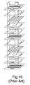
- FIG.9 is a view of a design for a flow channel in an interconnect of a SOFC according to a prior art.
- the interconnect comprises two inlets and one outlet where the velocity of the operation flow does not distribute evenly. The velocity of the operation flow between the inlets and the outlet is higher while that at two sides is lower.
- thermo- fluid electrochemical modeling of planar SOFC stacks by K. P. Recknagle, R. E. Williford, L. A. Chick, D. R. Rector, and M. A. Khaleel (Journal of Power Sources, 113, pp. 109-114, 2003 ), the impacts on the distribution of the temperature as well as current density in an electricity generation substrate made by the flow channel deployment of cross-flow, co-flow and counterflow are discussed.
- the distribution of the temperature as well as current density with a flow channel deployment of co-flow is most even; the fuel utilization with a flow channel deployment of counterflow is higher; and the highest distribution of the temperature as well as current density with a flow channel deployment of cross-flow is at the interflow of the fuel from the inlets and the air from the outlet.
- German patent of DE10039024A1 is a method for assembling a glass-ceramics-sealed SOFC stack.
- a co-flow for a glass-ceramics-sealed SOFC stack is designed, where the flow directions of the fuel and the air are the same; flow areas are formed by ribs and furrows in an interconnect; yet the design of the number of inlets and outlets and the detail design of the flow area are not described.
- the main purpose of the present invention is to evenly and smoothly flow operation flows of a fuel cell to an interconnect to uniform the current density distribution of an electricity generation substrate by way of a first and a second flow areas.
- the temperature differential in the fuel cell is lowered; the reliability of operation is improved; the performance of the fuel is elevated; and the usage period of the fuel cell is prolonged.
- the present invention is a flow channel on an interconnect of a planar SOFC, comprising a first flow area and a second flow area.
- the first flow area is deposed on a surface of the interconnect, comprising a first channel, at least one inlet at an end connecting with the first channel, and an outlet at the other end connecting with the first channel.
- the second flow area is deposed on the opposite surface of the interconnect, comprising a second channel, at least one inlet at an end connecting with the second channel while deposed at two sides of the outlet of the first flow area, and an outlet at the other end connecting with the second channel while deposed between the inlets of the first flow area.
- operation flows of the fuel cell can evenly and smoothly flow to the interconnect to uniform the current density distribution of the electricity generation substrate by way of the first and the second flow areas.
- the temperature differential in the fuel cell is lowered; the reliability of operation is improved; the performance of the fuel is elevated; and the usage period of the fuel cell is prolonged.
- a buffer area like a reservoir helps to slow down the velocity of a stream; besides, a design of divisional islands make a stream detoured to uniform the velocity of the stream by lengthening the distance.
- a turbine-blade equilibrated valve can do, the idea of such a valve can be extendedly applied to an equilibrium slot between the ribs of the interconnect so that the velocity can be uniformed by balancing the pressure with the design of the slot.
- a deflector also helps uniform the velocity.
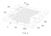
- FIG.1 and FIG.2 are a perspective view and another perspective view of a first preferred embodiment according to the present invention.
- the present invention is a flow channel on an interconnect of a planar SOFC, comprising a first flow area 11 and a second flow area 12 where operation flows of a fuel cell flow evenly and smoothly to the interconnect 1 to uniform the current density distribution of an electricity generation substrate (not shown in the figures).
- the temperature differential in the fuel cell is lowered; the reliability of operation is improved; the performance of the fuel is elevated; and the usage period of the fuel cell is prolonged.
- the first flow area 11 is deposed on a surface of the interconnect 1, comprising a first channel 111, where the channel comprises a plurality of ribs 112.
- a slot 113 is deposed between every two adjacent ribs 112 in a direction to form a flow path for flowing a first operation flow; and the area where the first operation flow flows through is an active area of the electricity generation substrate for generating an electricity power.
- Yet another slot 113a is also deposed between every two adjacent ribs 112 in a right-angle direction to uniform the pressure and to increase the active area.
- the first flow area 11 comprises at least one inlet 114 at an end connecting with the first channel 111.
- a plurality of deflecting parts 115 is deposed outside of a side of a brim of the inlet 114 to evenly distribute the velocity of the first operation flow.
- the first flow area 11 comprises one outlet 116 at the other end connecting with the first channel 111.
- a deflecting part 117 is deposed correspondingly outside of a side of a brim of the outlet 116 to increase the distance for the first operation flow to flow from the inlet 114 to the outlet 116 so that the velocity of the first operation flow of the two deflecting parts 115,117 can be uniformed.
- the brim at the end of the first channel 111 which is corresponding to the outlet 116 is in a curve shape to uniform the velocity of the first operation flow in the first flow area 11.
- the second flow area 12 comprising a second channel 121 with a plurality of ribs 122, is deposed on the opposite surface of the first interconnect 1.
- a slot 123 is deposed between every two adjacent ribs 122 in a direction to form a flow path for flowing the second operation flow; and the area where the second operation flow flows through is an active area of the electricity generation substrate for generating an electricity power.
- Yet another slot 123a is also deposed between every two adjacent ribs 122 in a right-angle direction to uniform the pressure and to increase the active area.
- the second flow area 12 comprises at least one inlet 124 at an end connecting with the second channel 121.
- a plurality of deflecting parts 125 at two sides of the outlet 116 of the first flow area 11 is deposed outside of a side of a brim of the inlet 124 to evenly distribute the velocity of the second operation flow.
- the second flow area 12, connecting with the second channel 121, comprises at the other end an outlet 126 between the inlets 114 of the first flow area 11.
- a deflecting part 127 is deposed correspondingly outside of a side of a brim of the outlet 126 to increase the distance for the second operation flow to flow from the inlet 124 to the outlet 126 so that the velocity of the second operation flow of the deflecting part 127 can be uniformed.
- the side of a brim of the second channel 121 which is corresponding to the outlet 126 is in a curve shape to uniform the velocity of the second operation flow in the second flow area 12.
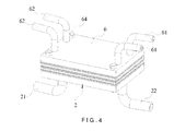
- FIG.3 through FIG.6 are an exploded view of an assembly, a view of the assembly, and views of the flow directions, of the first preferred embodiment according to the present invention.
- a base 2 is obtained first, which is connected with an output tube 21,22 at each end respectively.
- a first interconnect 1 is deposed on the base 2, and a second interconnect 1a is deposed on the first interconnect 1.
- a cover 6 is deposed on the second interconnect 1a, where the cover 6 is connected with an input tube 61,62 at each of two opposite ends respectively.
- a first electricity generation substrate 3 is deposed between the base 2 and the first interconnect 1 where a first washer 23,32 is deposed between the first substrate 3 and the base 2 as well as between the first substrate 3 and the first interconnect 1 both to prevent the operation flows from leaking from any gap.
- Outlets 116,116a are corresponding to an opening of an output tube 21 for outputting the first operation flow; and the other outlets 126,126a are corresponding to an opening of the other output tube 22 for outputting the second operation flow.
- a second electricity generation substrate 4 is deposed between the two interconnects 1,1a.
- a second washer 24,42 is deposed at the contact surface between the first interconnect 1 and the second substrate 4 as well as between the second interconnect 1a and the second substrate 4 both to prevent the operation flows from leaking from any gap.
- a third electricity generation substrate 5 is deposed between the cover 6 and the first interconnect 1 where a third washer 25,52 is deposed between the third substrate 5 and the second interconnect 1a as well as between the third substrate 5 and the cover 6 both to prevent the operation flows from leaking from any gap.
- Inlets 114,114a are corresponding to an opening of an input tube 61 for inputting the first operation flow; and the other inlets 124,124a are corresponding to an opening of the other input tube 62 for inputting the second operation flow.
- a flow area 26 of the base 2 is corresponding to a second flow area 12 of the first interconnect 1; a first flow area 11 of the first interconnect 1 is corresponding to a second flow area 12a of the second interconnect 1a; a first flow area 11a of the second interconnect 1a is corresponding to a flow area 63 of the cover 6; and, with the help of a locking part 64, the whole package is assembled and locked.
- a required first operation flow is directed from the input tube 61 of the cover 6, where the first operation flow is guided to flow from the inlet 114a at an end of the first flow area 11a on the second interconnect 1a to the first channel 111a of the second interconnect 1a; to flow from the first channel 111a to the outlet 116a of the second interconnect 1a; to flow through the outlet 116 of the first flow area 11 of the first interconnect 1; and to flow directly to the output tube 21 of the base 2.
- Another portion of the first operation flow is guided to flow directly from the input tube 61 of the cover 6 to the inlet 114 at the end of the first flow area 11 on the first interconnect 1; to flow to the first channel 111 of the first interconnect 1; to flow from the first channel 111 to the outlet 116 of the first interconnect 1; and to flow to the output tube 21 of the base 2.
- the other portion of the first operation flow flows directly from the input tube 61 of the cover 6 to the flow area 26 on the base 2 to be outputted through the output tube 21 of the base 2.
- a second operation flow is directed to flow from the other input tube 62 of the cover 6 to the outlet 126a of the second flow area 12a of the second interconnect 1a through the flow area 63 of the cover 6; and to flow directly to the output tube 22 of the base 2.
- Another portion of the second operation flow is guided to flow directly from the other input tube 62 of the cover 6 to the second channel 121a of the second interconnect 1a through the inlet 124a at an end of the second flow area 12a of the second interconnect 1a; to flow from the second channel 121a to the outlet 126a of the second flow area 12a; and to flow to be outputted through the output tube 22 of the base 2.
- the other portion of the second operation flow is guided to flow directly from the other input tube 62 of the cover 6 to the second channel 121 of the first interconnect 1 through the inlet 124 at the end of the second flow area 12 of the first interconnect 1; to flow from the second channel 121 to the outlet 126 of the first flow area 12 of the first interconnect 1; and to flow to be outputted through the output tube 22 of the base 2.
- FIG.7 and FIG.8, are a perspective view and another perspective view of a second preferred embodiment according to the present invention.
- the present invention is a flow channel on an interconnect of a planar SOFC, comprising a first flow area 11 and a second flow area 12.
- the first flow area 11 is deposed on a surface of the interconnect 1, comprising a first channel 111, where the channel comprises a plurality of ribs 112.
- a slot 113 are formed between every two adjacent ribs 112 in a direction; and another slot 113a, in a right-angle direction.
- the first flow area 11 comprises at least one inlet 114 at an end connecting with the first channel 111.
- a plurality of deflecting parts 115a is raised and deposed on a side of a brim of the inlet 114.
- the first flow area 11 comprises one outlet 116 at the other end connecting with the first channel 111.
- a deflecting part 117a is raised and deposed on a side of a brim of the outlet 116.
- the brim at the end of the first channel 111 which is corresponding to the outlet 116 is in a curve shape.
- the second flow area 12 comprising a second channel 121 with a plurality of ribs 122, is deposed on the opposite surface of the first interconnect 1.
- a slot 123 are formed between every two adjacent ribs 122 in a direction; and another slot 123a, in a right-angle direction.
- the second flow area 12 comprises at least one inlet 124 at an end connecting with the second channel 121.
- a plurality of deflecting parts 125a at two sides of the outlet 116 of the first flow area 11 is raised and deposed on a side of a brim of the inlet 124.
- the second flow area 12, connecting with the second channel 121 comprises at the other end an outlet 126 between the inlets 114 of the first flow area 11.
- a deflecting part 127a is raised and deposed correspondingly on a side of a brim of the outlet 126.
- a side of a brim of the second channel 121, which is corresponding to the outlet 126, is in a curve shape.
- the present invention is a flow channel on an interconnect of a planar SOFC, where operation flows of a fuel cell flow evenly and smoothly to an active area of the interconnect for a steady electricity generation.
Landscapes
- Life Sciences & Earth Sciences (AREA)
- Engineering & Computer Science (AREA)
- Manufacturing & Machinery (AREA)
- Sustainable Development (AREA)
- Sustainable Energy (AREA)
- Chemical & Material Sciences (AREA)
- Chemical Kinetics & Catalysis (AREA)
- Electrochemistry (AREA)
- General Chemical & Material Sciences (AREA)
- Fuel Cell (AREA)
Priority Applications (1)
| Application Number | Priority Date | Filing Date | Title |
|---|---|---|---|
| EP05105133A EP1732154A1 (fr) | 2005-06-10 | 2005-06-10 | Canal d'écoulement d'un interconnecteur de piles de combustible à oxide solide |
Applications Claiming Priority (1)
| Application Number | Priority Date | Filing Date | Title |
|---|---|---|---|
| EP05105133A EP1732154A1 (fr) | 2005-06-10 | 2005-06-10 | Canal d'écoulement d'un interconnecteur de piles de combustible à oxide solide |
Publications (1)
| Publication Number | Publication Date |
|---|---|
| EP1732154A1 true EP1732154A1 (fr) | 2006-12-13 |
Family
ID=35335687
Family Applications (1)
| Application Number | Title | Priority Date | Filing Date |
|---|---|---|---|
| EP05105133A Withdrawn EP1732154A1 (fr) | 2005-06-10 | 2005-06-10 | Canal d'écoulement d'un interconnecteur de piles de combustible à oxide solide |
Country Status (1)
| Country | Link |
|---|---|
| EP (1) | EP1732154A1 (fr) |
Cited By (7)
| Publication number | Priority date | Publication date | Assignee | Title |
|---|---|---|---|---|
| EP1852931A1 (fr) * | 2006-05-03 | 2007-11-07 | Samsung SDI Co., Ltd. | Séparateur de pile à combustible |
| JP2014116190A (ja) * | 2012-12-10 | 2014-06-26 | Honda Motor Co Ltd | 燃料電池スタック |
| EP2728655A4 (fr) * | 2011-06-28 | 2014-12-24 | Ngk Spark Plug Co | Pile à combustible à oxyde solide et interconnecteur |
| EP2937926A4 (fr) * | 2012-12-18 | 2015-11-18 | Posco Energy Co Ltd | Pile à combustible à oxyde solide ayant un canal vertical et un canal transversal |
| EP2579371A4 (fr) * | 2010-05-26 | 2016-12-14 | Ngk Spark Plug Co | Pile à combustible à oxyde solide |
| CN112904205A (zh) * | 2019-12-03 | 2021-06-04 | 中国科学院大连化学物理研究所 | 一种燃料电池测量装置 |
| CN117727967A (zh) * | 2023-11-14 | 2024-03-19 | 中国科学院上海应用物理研究所 | 一种固体氧化物燃料电池或电解池的连接体 |
Citations (4)
| Publication number | Priority date | Publication date | Assignee | Title |
|---|---|---|---|---|
| US4910100A (en) * | 1989-07-21 | 1990-03-20 | Fuji Electric Co., Ltd. | Solid electrolyte fuel cell |
| US5162167A (en) * | 1990-09-11 | 1992-11-10 | Allied-Signal Inc. | Apparatus and method of fabricating a monolithic solid oxide fuel cell |
| US6296962B1 (en) * | 1999-02-23 | 2001-10-02 | Alliedsignal Inc. | Design for solid oxide fuel cell stacks |
| DE10039024A1 (de) * | 2000-08-10 | 2002-02-28 | Forschungszentrum Juelich Gmbh | Brennstoffzellenstapel mit internen Gasanschlüssen |
-
2005
- 2005-06-10 EP EP05105133A patent/EP1732154A1/fr not_active Withdrawn
Patent Citations (4)
| Publication number | Priority date | Publication date | Assignee | Title |
|---|---|---|---|---|
| US4910100A (en) * | 1989-07-21 | 1990-03-20 | Fuji Electric Co., Ltd. | Solid electrolyte fuel cell |
| US5162167A (en) * | 1990-09-11 | 1992-11-10 | Allied-Signal Inc. | Apparatus and method of fabricating a monolithic solid oxide fuel cell |
| US6296962B1 (en) * | 1999-02-23 | 2001-10-02 | Alliedsignal Inc. | Design for solid oxide fuel cell stacks |
| DE10039024A1 (de) * | 2000-08-10 | 2002-02-28 | Forschungszentrum Juelich Gmbh | Brennstoffzellenstapel mit internen Gasanschlüssen |
Non-Patent Citations (3)
| Title |
|---|
| RECKNAGLE K P ET AL: "Three-dimensional thermo-fluid electrochemical modeling of planar SOFC stacks", JOURNAL OF POWER SOURCES, ELSEVIER, AMSTERDAM, NL, vol. 113, no. 1, 1 January 2003 (2003-01-01), pages 109 - 114, XP004399050, ISSN: 0378-7753 * |
| WEN T-L ET AL: "Material research for planar SOFC stack", SOLID STATE IONICS, NORTH HOLLAND PUB. COMPANY. AMSTERDAM, NL, vol. 148, no. 3-4, 2 June 2002 (2002-06-02), pages 513 - 519, XP004361855, ISSN: 0167-2738 * |
| YAKABE H ET AL: "3-D model calculation for planar SOFC", JOURNAL OF POWER SOURCES, ELSEVIER, AMSTERDAM, NL, vol. 102, no. 1-2, 1 December 2001 (2001-12-01), pages 144 - 154, XP004331030, ISSN: 0378-7753 * |
Cited By (10)
| Publication number | Priority date | Publication date | Assignee | Title |
|---|---|---|---|---|
| EP1852931A1 (fr) * | 2006-05-03 | 2007-11-07 | Samsung SDI Co., Ltd. | Séparateur de pile à combustible |
| JP2007299726A (ja) * | 2006-05-03 | 2007-11-15 | Samsung Sdi Co Ltd | 燃料電池用セパレータ |
| EP2579371A4 (fr) * | 2010-05-26 | 2016-12-14 | Ngk Spark Plug Co | Pile à combustible à oxyde solide |
| EP2728655A4 (fr) * | 2011-06-28 | 2014-12-24 | Ngk Spark Plug Co | Pile à combustible à oxyde solide et interconnecteur |
| US9455454B2 (en) | 2011-06-28 | 2016-09-27 | Ngk Spark Plug Co., Ltd. | Solid oxide fuel cell and inter-connector |
| JP2014116190A (ja) * | 2012-12-10 | 2014-06-26 | Honda Motor Co Ltd | 燃料電池スタック |
| EP2937926A4 (fr) * | 2012-12-18 | 2015-11-18 | Posco Energy Co Ltd | Pile à combustible à oxyde solide ayant un canal vertical et un canal transversal |
| US10446856B2 (en) | 2012-12-18 | 2019-10-15 | Posco Energy Co., Ltd. | Solid oxide fuel cell having longitudinal and lateral channels |
| CN112904205A (zh) * | 2019-12-03 | 2021-06-04 | 中国科学院大连化学物理研究所 | 一种燃料电池测量装置 |
| CN117727967A (zh) * | 2023-11-14 | 2024-03-19 | 中国科学院上海应用物理研究所 | 一种固体氧化物燃料电池或电解池的连接体 |
Similar Documents
| Publication | Publication Date | Title |
|---|---|---|
| CN107887623B (zh) | 用于内部歧管式固体氧化物燃料电池堆叠的互连件以及相关方法和电力系统 | |
| JP4960415B2 (ja) | 燃料電池 | |
| TR201809360T4 (tr) | Yakıt hücresi için gaz dağıtım elemanı. | |
| JP2012129194A (ja) | 燃料電池 | |
| US20080305382A1 (en) | Flow-Field Plate and Fuel Cell Stack Using the Same | |
| US20060286431A1 (en) | Flow channel on interconnect of planar solid oxide fuel cell | |
| JP5302263B2 (ja) | 燃料電池 | |
| JPWO2011064961A1 (ja) | 燃料電池用セパレータ及びそれを備える燃料電池 | |
| US8153330B2 (en) | Fuel cell separator stacked on an electrolyte electrode assembly | |
| US9391332B2 (en) | Fluid flow plate assemblies for use in fuel cells having flow channels with substantially same length | |
| US20070207363A1 (en) | Interconnect set of planar solid oxide fuel cell having flow paths | |
| JP2021512472A (ja) | 燃料電池、単セル及びセルスタック構造体 | |
| CN107810572A (zh) | 隔板、其制造方法和包括隔板的燃料电池堆 | |
| US8557467B2 (en) | Fuel cell and fuel cell stack | |
| JP5491231B2 (ja) | 燃料電池 | |
| KR102080573B1 (ko) | Soec 장치용 가스 유입구 | |
| EP1830425A1 (fr) | Ensemble d'éléments d'interconnexion avec des voies d'écoulement pour piles à combustible à haute temperature | |
| KR101932803B1 (ko) | 분리판 및 이를 포함하는 연료전지 스택 | |
| CN105393394A (zh) | 用于soc单元的气体入口 | |
| JP2006164762A (ja) | 燃料電池の配流特性の改善 | |
| JP3122087U (ja) | フラットベット型固態酸化物燃料電池連接板パッケージ構造 | |
| US8129066B2 (en) | Fuel cell exhibiting enhanced hydrogen distribution density | |
| JP7548127B2 (ja) | 燃料電池用のセパレータ | |
| CN120221700B (zh) | 一种基于仿生结构的质子交换膜燃料电池双极板流道结构 | |
| CN116072944B (zh) | 一种单堆兆瓦级燃料电池 |
Legal Events
| Date | Code | Title | Description |
|---|---|---|---|
| PUAI | Public reference made under article 153(3) epc to a published international application that has entered the european phase |
Free format text: ORIGINAL CODE: 0009012 |
|
| AK | Designated contracting states |
Kind code of ref document: A1 Designated state(s): AT BE BG CH CY CZ DE DK EE ES FI FR GB GR HU IE IS IT LI LT LU MC NL PL PT RO SE SI SK TR |
|
| AX | Request for extension of the european patent |
Extension state: AL BA HR LV MK YU |
|
| 17P | Request for examination filed |
Effective date: 20070613 |
|
| RIN1 | Information on inventor provided before grant (corrected) |
Inventor name: YEN, CHENG-HO Inventor name: CHENG, YUNG-NENG Inventor name: SHY, SHENQ-YANG Inventor name: CHYOU, YAU-PIN |
|
| AKX | Designation fees paid |
Designated state(s): AT BE BG CH CY CZ DE DK EE ES FI FR GB GR HU IE IS IT LI LT LU MC NL PL PT RO SE SI SK TR |
|
| 17Q | First examination report despatched |
Effective date: 20071106 |
|
| STAA | Information on the status of an ep patent application or granted ep patent |
Free format text: STATUS: THE APPLICATION IS DEEMED TO BE WITHDRAWN |
|
| 18D | Application deemed to be withdrawn |
Effective date: 20090709 |