EP1732178A2 - Verbindungsanordnung und Vakuumpumpe - Google Patents
Verbindungsanordnung und Vakuumpumpe Download PDFInfo
- Publication number
- EP1732178A2 EP1732178A2 EP06252885A EP06252885A EP1732178A2 EP 1732178 A2 EP1732178 A2 EP 1732178A2 EP 06252885 A EP06252885 A EP 06252885A EP 06252885 A EP06252885 A EP 06252885A EP 1732178 A2 EP1732178 A2 EP 1732178A2
- Authority
- EP
- European Patent Office
- Prior art keywords
- connector
- control device
- main body
- outer cylinder
- cable
- Prior art date
- Legal status (The legal status is an assumption and is not a legal conclusion. Google has not performed a legal analysis and makes no representation as to the accuracy of the status listed.)
- Withdrawn
Links
- 238000000465 moulding Methods 0.000 claims description 27
- 239000004020 conductor Substances 0.000 claims description 17
- 230000033228 biological regulation Effects 0.000 claims description 3
- 230000001105 regulatory effect Effects 0.000 claims description 2
- 238000007789 sealing Methods 0.000 abstract description 4
- 238000003780 insertion Methods 0.000 abstract description 3
- 230000037431 insertion Effects 0.000 abstract description 3
- 230000007704 transition Effects 0.000 abstract description 2
- 239000007789 gas Substances 0.000 description 18
- 125000006850 spacer group Chemical group 0.000 description 16
- 229910052751 metal Inorganic materials 0.000 description 13
- 239000002184 metal Substances 0.000 description 13
- XEEYBQQBJWHFJM-UHFFFAOYSA-N Iron Chemical compound [Fe] XEEYBQQBJWHFJM-UHFFFAOYSA-N 0.000 description 10
- 230000006870 function Effects 0.000 description 10
- 230000002093 peripheral effect Effects 0.000 description 9
- 239000011347 resin Substances 0.000 description 8
- 229920005989 resin Polymers 0.000 description 8
- 238000006073 displacement reaction Methods 0.000 description 7
- 239000004065 semiconductor Substances 0.000 description 7
- 230000006872 improvement Effects 0.000 description 6
- 238000010276 construction Methods 0.000 description 5
- 229910052742 iron Inorganic materials 0.000 description 5
- 229910052782 aluminium Inorganic materials 0.000 description 4
- XAGFODPZIPBFFR-UHFFFAOYSA-N aluminium Chemical compound [Al] XAGFODPZIPBFFR-UHFFFAOYSA-N 0.000 description 4
- 230000000694 effects Effects 0.000 description 4
- 238000010438 heat treatment Methods 0.000 description 4
- 230000009467 reduction Effects 0.000 description 4
- 238000005476 soldering Methods 0.000 description 4
- RYGMFSIKBFXOCR-UHFFFAOYSA-N Copper Chemical compound [Cu] RYGMFSIKBFXOCR-UHFFFAOYSA-N 0.000 description 3
- 229910052802 copper Inorganic materials 0.000 description 3
- 239000010949 copper Substances 0.000 description 3
- 238000010586 diagram Methods 0.000 description 3
- 238000000034 method Methods 0.000 description 3
- 230000008569 process Effects 0.000 description 3
- 238000010926 purge Methods 0.000 description 3
- 239000010935 stainless steel Substances 0.000 description 3
- 229910001220 stainless steel Inorganic materials 0.000 description 3
- 239000000758 substrate Substances 0.000 description 3
- 229910045601 alloy Inorganic materials 0.000 description 2
- 239000000956 alloy Substances 0.000 description 2
- 238000001514 detection method Methods 0.000 description 2
- 239000000428 dust Substances 0.000 description 2
- 238000004519 manufacturing process Methods 0.000 description 2
- 239000000463 material Substances 0.000 description 2
- 150000002739 metals Chemical class 0.000 description 2
- 230000009471 action Effects 0.000 description 1
- 238000005452 bending Methods 0.000 description 1
- 230000001276 controlling effect Effects 0.000 description 1
- 238000011161 development Methods 0.000 description 1
- 230000018109 developmental process Effects 0.000 description 1
- 238000010894 electron beam technology Methods 0.000 description 1
- 238000005530 etching Methods 0.000 description 1
- 230000005284 excitation Effects 0.000 description 1
- 239000012535 impurity Substances 0.000 description 1
- 238000012423 maintenance Methods 0.000 description 1
- 230000014759 maintenance of location Effects 0.000 description 1
- 230000015654 memory Effects 0.000 description 1
- 230000035699 permeability Effects 0.000 description 1
- 230000001681 protective effect Effects 0.000 description 1
- 238000012546 transfer Methods 0.000 description 1
Images



Classifications
-
- H—ELECTRICITY
- H01—ELECTRIC ELEMENTS
- H01R—ELECTRICALLY-CONDUCTIVE CONNECTIONS; STRUCTURAL ASSOCIATIONS OF A PLURALITY OF MUTUALLY-INSULATED ELECTRICAL CONNECTING ELEMENTS; COUPLING DEVICES; CURRENT COLLECTORS
- H01R13/00—Details of coupling devices of the kinds covered by groups H01R12/70 or H01R24/00 - H01R33/00
- H01R13/62—Means for facilitating engagement or disengagement of coupling parts or for holding them in engagement
- H01R13/629—Additional means for facilitating engagement or disengagement of coupling parts, e.g. aligning or guiding means, levers, gas pressure electrical locking indicators, manufacturing tolerances
- H01R13/631—Additional means for facilitating engagement or disengagement of coupling parts, e.g. aligning or guiding means, levers, gas pressure electrical locking indicators, manufacturing tolerances for engagement only
- H01R13/6315—Additional means for facilitating engagement or disengagement of coupling parts, e.g. aligning or guiding means, levers, gas pressure electrical locking indicators, manufacturing tolerances for engagement only allowing relative movement between coupling parts, e.g. floating connection
-
- F—MECHANICAL ENGINEERING; LIGHTING; HEATING; WEAPONS; BLASTING
- F04—POSITIVE - DISPLACEMENT MACHINES FOR LIQUIDS; PUMPS FOR LIQUIDS OR ELASTIC FLUIDS
- F04D—NON-POSITIVE-DISPLACEMENT PUMPS
- F04D19/00—Axial-flow pumps
- F04D19/02—Multi-stage pumps
- F04D19/04—Multi-stage pumps specially adapted to the production of a high vacuum, e.g. molecular pumps
-
- F—MECHANICAL ENGINEERING; LIGHTING; HEATING; WEAPONS; BLASTING
- F04—POSITIVE - DISPLACEMENT MACHINES FOR LIQUIDS; PUMPS FOR LIQUIDS OR ELASTIC FLUIDS
- F04D—NON-POSITIVE-DISPLACEMENT PUMPS
- F04D25/00—Pumping installations or systems
- F04D25/02—Units comprising pumps and their driving means
- F04D25/06—Units comprising pumps and their driving means the pump being electrically driven
- F04D25/0693—Details or arrangements of the wiring
-
- H—ELECTRICITY
- H01—ELECTRIC ELEMENTS
- H01R—ELECTRICALLY-CONDUCTIVE CONNECTIONS; STRUCTURAL ASSOCIATIONS OF A PLURALITY OF MUTUALLY-INSULATED ELECTRICAL CONNECTING ELEMENTS; COUPLING DEVICES; CURRENT COLLECTORS
- H01R13/00—Details of coupling devices of the kinds covered by groups H01R12/70 or H01R24/00 - H01R33/00
- H01R13/62—Means for facilitating engagement or disengagement of coupling parts or for holding them in engagement
- H01R13/629—Additional means for facilitating engagement or disengagement of coupling parts, e.g. aligning or guiding means, levers, gas pressure electrical locking indicators, manufacturing tolerances
- H01R13/631—Additional means for facilitating engagement or disengagement of coupling parts, e.g. aligning or guiding means, levers, gas pressure electrical locking indicators, manufacturing tolerances for engagement only
-
- H—ELECTRICITY
- H01—ELECTRIC ELEMENTS
- H01R—ELECTRICALLY-CONDUCTIVE CONNECTIONS; STRUCTURAL ASSOCIATIONS OF A PLURALITY OF MUTUALLY-INSULATED ELECTRICAL CONNECTING ELEMENTS; COUPLING DEVICES; CURRENT COLLECTORS
- H01R13/00—Details of coupling devices of the kinds covered by groups H01R12/70 or H01R24/00 - H01R33/00
- H01R13/73—Means for mounting coupling parts to apparatus or structures, e.g. to a wall
- H01R13/74—Means for mounting coupling parts in openings of a panel
-
- Y—GENERAL TAGGING OF NEW TECHNOLOGICAL DEVELOPMENTS; GENERAL TAGGING OF CROSS-SECTIONAL TECHNOLOGIES SPANNING OVER SEVERAL SECTIONS OF THE IPC; TECHNICAL SUBJECTS COVERED BY FORMER USPC CROSS-REFERENCE ART COLLECTIONS [XRACs] AND DIGESTS
- Y10—TECHNICAL SUBJECTS COVERED BY FORMER USPC
- Y10S—TECHNICAL SUBJECTS COVERED BY FORMER USPC CROSS-REFERENCE ART COLLECTIONS [XRACs] AND DIGESTS
- Y10S439/00—Electrical connectors
- Y10S439/901—Connector hood or shell
Definitions
- the present invention relates to a terminal structure and a vacuum pump, and in particular, to a terminal structure capable of preventing damage due to an excessive force and having high sealing property, and a vacuum pump to which the terminal structure is applied.
- Such semiconductor devices are manufactured by doping semiconductor substrates of a very high purity with impurities to impart electrical properties thereto, by forming minute circuits on the semiconductor substrates through etching, etc.
- a vacuum pump is generally used; in particular, a turbo molecular pump, which is a kind of vacuum pump, is widely used since it allows maintenance with ease, etc.
- a semiconductor manufacturing process involves a number of steps of causing various process gasses to act on a semiconductor substrate, and the turbo molecular pump is used not only to create a vacuum in the chamber but also to evacuate such process gases from the chamber.
- a turbo molecular pump is used to create a high vacuum state within the chamber of the electron microscope, etc. in order to prevent refraction, etc. of the electron beam due to the presence of dust or the like.
- turbo molecular pump is composed of a turbo molecular pump main body for sucking gas from the chamber of a semiconductor manufacturing apparatus, the electron microscope, or the like, and a control device for controlling the turbo molecular pump main body.
- FIG. 5 shows a longitudinal sectional view of the turbo molecular pump main body.
- a turbo molecular pump main body 100 has an inlet port 101 formed at the upper end of an outer cylinder 127.
- a rotor 103 On an inner side of the outer cylinder 127, there is provided a rotor 103 in a periphery of which there are formed radially and in a number of stages a plurality of rotary vanes 102a, 102b, 102c, ... formed of turbine blades for sucking and evacuating gases.
- a rotor shaft 113 Mounted at a center of this rotor 103 is a rotor shaft 113, which is levitatingly supported and position-controlled by, for example, a so-called 5-axis control magnetic bearing.
- Upper radial electromagnets 104 are four electromagnets arranged in pairs in an X-axis and an Y-axis . In close proximity to and in correspondence with the upper radial electromagnets 104, there are provided four upper radial sensors 107. The upper radial sensors 107 detect radial displacement of the rotor 103, and transmit displacement signals to a control device 200.
- the control device 200 controls the excitation of the upper radial electromagnets 104 by an output of an amplifier transmitted through a magnetic bearing control circuit having a PID adjustment function, and adjusts the radial position of an upper side of the rotor shaft 113.
- the magnetic bearing control circuit converts analog sensor signals representing the displacement of the rotor shaft 113 detected by the upper radial sensors 107 into digital signals by an A/D converter, and processes the signals to adjust electric current caused to flow through the upper radial electromagnets 104, levitating the rotor shaft 113.
- the electric current caused to flow through the upper radial electromagnets 104 is measured, and fed back to the magnetic bearing control circuit.
- the rotor shaft 113 is formed of a high magnetic permeability material (such as iron), and is attracted by the magnetic force of the upper radial electromagnets 104. Such adjustment is effected independently in the X-axis and the Y-axis directions.
- lower radial electromagnets 105 and lower radial sensors 108 are arranged in the same way as the upper radial electromagnets 104 and the upper radial sensors 107, and the lower radial position of the of the rotor shaft 113 is adjusted by the control device 200 in the same manner as the upper radial position thereof.
- axial electromagnets 106A and 106B are arranged so as to sandwich from above and below a circular metal disc 111 provided in a lower portion of the rotor shaft 113.
- the metal disc 111 is formed ofahigh magnetic-permeability material,such asiron.
- axial sensors 109 for detecting an axial displacement of the rotor shaft 113. Axial displacement signals obtained through detection by the axial sensors 109 are transmitted to the control device 200.
- the axial electromagnets 106A and 106B are excited and controlled by the output of the amplifier transmitted through the magnetic bearing control circuit with a PID adjustment function of the control device 200.
- the axial electromagnets 106A attract the metal disc 111 upwards by the magnetic force, and the axial electromagnets 106B attract the metal disc 111 downwards.
- control device 200 appropriately adjusts the magnetic forces exerted on the metal disc 111 by the axial electromagnets 106A and 106B, and magnetically levitates the rotor shaft 113 in the axial direction, retaining it in the air in a non-contact fashion.
- a motor 121 is equipped with a plurality of magnetic poles circumferentially arranged so as to surround the rotor shaft 113. Each of these magnetic poles is controlled so as to rotate and drive the motor 121 by a power signal output from a drive circuit and transmitted through a motor control circuit with a PWM control function of the control device 200.
- the motor 121 is equipped with an RPM sensor and a motor temperature detecting sensor (not shown).
- the RPM of the rotor shaft 113 is controlled by the control device 200 on the basis of detection signals received from the RPM sensor and the motor temperature detecting sensor.
- the rotary vanes 102a, 102b, 102c, ... are inclined by a predetermined angle with respect to planes perpendicular to the axis of the rotor shaft 113.
- the stationary vanes 123 are inclined by a predetermined angle with respect to planes perpendicular to the axis of the rotor shaft 113, and are arranged so as to protrude toward the interior of the outer cylinder 127 and in alternate stages with the rotary vanes 102.
- one ends of the stationary vanes 123 are supported while being inserted between a plurality of stationary vane spacers 125a, 125b, 125c, ... stacked together.
- the stationary vane spacers 125 are ring-like members formed of a metal, such as aluminum, iron, stainless steel, or copper, or a metal such as an alloy containing those metals as the components.
- the outer cylinder 127 is fixed in position with a slight gap therebetween.
- a base portion 129 is provided at a bottom portion of the outer cylinder 127.
- a threaded spacer 131 is provided in the portion of the base portion 129 which is below the threaded spacer 131.
- the threaded spacer 131 is a cylindrical member formed of a metal, such as aluminum, copper, stainless steel, or iron, or a metal such as an alloy containing those metals as the components, and has in an inner peripheral surface thereof a plurality of spiral thread grooves 131a formed.
- the spiral direction of the thread grooves 131a is a direction in which, when the molecules of the exhaust gas move in the rotating direction of the rotor 103, these molecules are transferred toward the exhaust port 133.
- a rotary vane 102d In the lowermost portion of the rotor 103 connected to the rotary vanes 102a, 102b, 102c, ... , there is provided a rotary vane 102d vertically downwards.
- the rotary vane 102d has an outer peripheral surface of a cylindrical shape, protrudes toward the inner peripheral surface of the threaded spacer 131, and is placed in close proximity to the threaded spacer 131 with a predetermined gap therebetween.
- the base portion 129 is a disc-like member constituting a base portion of the turbo molecular pump main body 100, and is generally formed of a metal, such as iron, aluminum, or stainless steel.
- the base portion 129 physically retains the turbo molecular pump main body 100, and also functions as a heat conduction path, so it is desirable to use a metal that is rigid and of high heat conductivity, such as iron, aluminum, or copper, for the base portion 129.
- a connector 160 is arranged on the base portion 129.
- the connector 160 serves as an outlet for signal lines between the turbo molecular pump main body 100 and the control device 200.
- the turbo molecular pump main body 100 side portion of the connector 160 is formed as a male terminal and the control device 200 side portion thereof is formed as a female terminal.
- the connector 160 has a seal structure, which is detachable, and capable of maintaining a vacuum inside the turbo molecular pump main body 100.
- the exhaust gas sucked in through the inlet port 101 flows between the rotary vanes 102 and the stationary vanes 123 to be transferred to the base portion 129.
- the exhaust gas transferred to the base portion 129 is sent to the exhaust port 133 while being guided by the thread grooves 131a of the threaded spacer 131.
- the threaded spacer 131 is provided in the outer periphery of the rotary vane 102d, and the thread grooves 131a are formed in the inner peripheral surface of the threaded spacer 131.
- the thread grooves may be formed in the outer peripheral surface of the rotary vane 102d, and a spacer with a cylindrical inner peripheral surface may be arranged in the periphery thereof.
- a predetermined pressure is maintained with a purge gas.
- piping (not shown) is arranged in the base portion 129, and the purge gas is introduced through the piping.
- the purge gas thus introduced flows through the gaps between a protective bearing 120 and the rotor shaft 113, between a rotor and stator of the motor 121, and between a stator column 122 and the rotary vanes 102 before being transmitted to the exhaust port 133.
- turbo molecular pump main body 100 and the control device 200 are usually formed as separate components, they are, in some cases, integrated with each other for a space saving as shown in JP 10-103288 A and JP 11-173293 A .
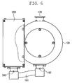
- FIG. 6 shows an example in which the turbo molecular pump main body 100 and the control device 200 are not separated but integrated with each other.
- cables 161 are attached to the connector 160 on the turbo molecular pump main body 100 side.
- a connector 260 is arranged at the other end of the cables 161 so as to be detachable with respect to the control device 200.
- the connector 160 and the connector 260 respectively protrude from the side portion of the turbo molecular pump main body 100 and the control device 200, with the cables in a bundle extending between the connectors.
- the number of cables is 30 or more, so a large size vacuum connector is required.
- the cables are thick, and their bending radius is large. However, they are flexible to a certain degree, so they are not easily damaged or the like by an excessive force applied at the time of assembly. On the other hand, they involve a problem in terms of space.
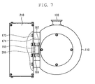
- turbo molecular pump main body and the control device are integrated with each other, instead of exposing the cables outside the turbo molecular pump main body 100 and the control device 200 as shown in FIG. 6, it is possible, as shown in FIG. 7, to directly connect a male connector 165 protruding from a turbo molecular pump main body 110 with a female connector 265 protruding from a control device 210.
- the male connector 165 is a vacuum connector, and is fastened to the turbo molecular pump main body 110 by bolts 167.
- the female connector 265 is similarly fastened to the control device 210 by bolts 169.
- a plurality of spacers 171 are provided between the turbo molecular pump main body 110 and the control device 210.
- the spacers 171 are formed as hollow cylinders, and bolts 173 are passed through them so as to fix the turbo molecular pump main body 110 and the control device 210 to each other through the intermediation of the spacers 171.
- the male connector 165 is fastened to the turbo molecular pump main body 110 by the bolts
- the female connector 265 is fastened to the control device 210 by the bolts, so, when, for example, the control device 210 is inserted obliquely to attach it to the turbo molecular pump main body 110, an excessive force may be exerted between the male connector 165 and the female connector 265, resulting in damage of the connectors.
- the present invention has been made in view of the above problems in the prior art. It is an object of the present invention to provide a terminal structure capable of preventing damage due to an excessive force and having high sealing property, and a vacuum pump to which the terminal structure is applied.
- a terminal structure of the present invention (Claim 1) is constructed by including: a first connector; a first member having the first connector; a second connector electrically connected by being fit-engaged with the first connector; a second member having the second connector; and elastic retaining means for elastically retaining the first connector with respect to the first member, and/or elastically retaining the second connector with respect to the second member.
- the terminal structure of the present invention (Claim 2) is constructed by including movement regulating means for effecting regulation to prevent a distance through which the fit-engagement is effected from exceeding a predetermined length.
- the present invention relates to a vacuum pump (Claim 3) according Claim 1 or 2, characterized in that the first member is applied to a vacuum pump main body, and the second member is applied to a control device.
- the vacuum pump main body and the control device are integrated with each other. Even when the control device is inserted somewhat obliquely with respect to the vacuum pump main body, and an excessive force is exerted between the connectors, it is possible to mitigate the force by the elastic retaining means, so there is no fear of the connectors suffering damage. Thus, there is little fear of a gas leakage occurring from the vacuum pump main body to cause a pump heating, an electrical short-circuiting, a leakage of current, etc., thereby achieving an improvement in terms of the reliability of the pump.
- the vacuum pump of the present invention (Claim 4) is constructed of: at least one cable whose conductor is exposed at a portion between both ends of the cable; a molding member formed through solidification-molding with at least the exposed conductor portion of the cable included; and an outer cylinder to or with which the molding member is mounted or integrated.
- the cable is molded with a resin or the like with the conductor exposed, so it is possible to prevent the gas leakage through a gap between the conductor and the cable covering.
- the pump and the control circuit are connected to each other by the cable, so even if an excessive force is applied, the cable simply deflects, and there is no fear of the connectors suffering damage.
- the vacuum pump of the present invention (Claim 5) is constructed by including: at least one pin with conductivity; cable conductor fixing means arranged at both ends of the pin and allowing conductors of cables fixed to the pin; a molding member formed through solidification-molding with the pin included; and an outer cylinder to or with which the molding member is mounted or integrated.
- a molding member composed of a resin or the like is solidification-molded with the pin included. Thus, there is no gap between the molding member and the pin, maintaining a vacuum seal therebetween.
- a seal member such as an O-ring, between the molding member and the outer cylinder. With this arrangement, it is possible to effect a vacuum seal without using a large vacuum connector, and it is possible to realize a space saving and a reduction in cost.
- the pump and the control circuit are connected to each other by the cable, so even if an excessive force is applied, the cable simply deflects, and there is no fear of the connector suffering damage.
- An end portion of the cable entering the control device can be connected to a miniature terminal or directly connected to the board, etc., whereby a space saving is achieved, and the mounting is easy to perform.
- the vacuum pump of the present invention (Claim 6) is characterized in that: a control device is provided side by side with the outer cylinder; a cable inside the outer cylinder and a cable inside the control device are electrically connected through the molding member; and the solidification-molded portion of the molding member and at least one of the portion of the molding member mounted to the outer cylinder, and the portion of the molding member integrated with the outer cylinder, are formed as seals.
- the apparatus By arranging the outer cylinder and the control device side by side, the apparatus as a whole is made compact.
- FIG. 1 is a schematic view of a terminal structure according to a first embodiment of the present invention.
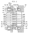
- a male connector 500 and a female connector 600 are arranged on a turbo molecular pump main body 300 side and a control device 400 side, respectively.
- the male connector 500 has a cylindrical wall 503 protruding in a cylindrical fashion toward the control device 400 side from an outer peripheral edge of a thick bottom portion 501, and, inside the male connector 500, there is formed a columnar cavity 504 surrounded by the cylindrical wall 503 and the bottom portion 501. Further, a disc-like flange portion 505 is arranged around the bottom portion 501. In the flange portion 505, there are formed a plurality of through-holes 507, through which bolts 509 are passed to be inserted into and fixed to an outer cylinder 127 of the turbo molecular pump main body 300.
- each male pin 511 Forty-one male pins 511 are passed through and fixed to the bottom portion 501 while arranged at equal intervals.
- a head portion 511a at one end of each male pin 511 is formed in a semi-spherical configuration, and an elongated hole 513 is formed at another end portion 511b so as to allow soldering after passing a cable core (not shown).
- the bottom portion 501 is formed of a resin, and a sufficient sealing property is secured between it and the male pins 511.
- the female connector 600 arranged on the control device 400 side has a cylindrical wall 603 protruding in a cylindrical fashion toward the turbo molecular pump main body 300 side from an outer peripheral edge of a thick bottom portion 601, and, in side the female connector 600, there is formed a columnar cavity 604 surrounded by the cylindrical wall 603 and the bottom portion 601. Further, a disc-like flange portion 605 is arranged around the bottom portion 601. A plurality of through-holes 607 are provided in the flange portion 605.
- a flat plate 609 is arranged so as to be opposed to the flange portion 605.
- the flat plate 609 has through-holes 611 at positions opposed to the through-holes 607 of the flange portion 605.
- Female screws are cut in the inner side of the through-holes 611.
- a circular hole 617 At a center of the flat plate 609, there is formed a circular hole 617, through which the bottom portion 601 can pass.
- Elastic and hollow waved washers 613 are arranged around the through-holes 607 and the through-holes 611 between the flange portion 605 and the flat plate 609. Bolts 615 are passed through the through-holes 607, the through-holes 611, and the waved washers 613 to be fastened to a casing wall of the control device 400.
- each female pin 621 is passed through and fixed to the bottom portion 601 while arranged at equal intervals.
- a pin insertion elongated hole 624 into which the semi-spherical head portion 511a at one end of each male pin 511 is to be inserted.
- an elongated hole 623 in another end portion 621b of each female pin, there is formed an elongated hole 623 so as to allow soldering after passing a cable core (not shown).
- a space defined by the cavity 604 and the female pins 621 is filled with a resin.
- FIG. 1 shows a state prior to the connection of the connectors
- FIG. 2 shows a state after the connection of the connectors.
- FIG. 3 is a schematic sectional view of the second embodiment of the present invention.
- an opening 701 is provided in the outer cylinder 127 of a turbo molecular pump main body 700.
- a control device 800 is integrated with the turbo molecular pump main body 700 through the opening 701.
- a plurality of cables 703 are passed through the opening 701.
- the cables 703 are fixed in position through molding with a resin. Further, a molding member 704 thus formed of the resin is fixed to or integrated with the opening 701. End portions of the cables 703 entering the control device 800 are connected to miniature terminals (not shown), directly connected to the board, etc.
- the cables 703 entering the control device 800 may be bundled for wiring, or separated into units of one to several cables to be connected to terminals.
- the miniature terminals may be small-sized ones as currently used in personal computers or the like, and constructed so as to be mounted to a board.
- the cables 703 are molded with a resin with the conductors 705 exposed, so it is possible to prevent the gas leakage through gaps between the conductors and the cable covering. As a result, it is possible to effect a vacuum seal without using a large vacuum connector. Thus, it is possible to realize a space saving and a reduction in cost.
- the pump and the control circuit are connected to each other by the cables 703, so even if an excessive force is applied, the cables simply deflect, and there is no fear of the connectors suffering damage. Thus, there is little fear of a gas leakage occurring from the turbo molecular pump main body 300 to cause a pump heating, an electrical short-circuiting, a leakage of current, etc., thereby achieving an improvement in terms of the reliability of the pump.
- FIG. 4 is a schematic sectional view of the third embodiment of the present invention.
- the opening 701 is provided in the outer cylinder 127 of the turbo molecular pump main body 700.
- the control device 800 is integrated with the turbo molecular pump main body 700 through the opening 701.
- a plurality of pins 707 are passed through the opening 701.
- each pin 707 there are formed elongated holes 723 and 725 so as to allow soldering after passing cores 719 and 721 of cables 713 and 715, respectively.
- a resin is solidification-molded with the pins 707 included.
- a covering member 729 thus formed through solidification-molding is composed of a protrusion 729a fit-engaged with the opening 701 and a bottom portion 729b covering the outer cylinder 127 of the turbo molecular pump main body 700.
- a plurality of through-holes 731 are provided in the bottom portion 729b of the covering member 729, and the covering member 729 is fastened to the outer cylinder 127 of the turbomolecular pump main body 700 by bolts 733 passing through the through-holes 731.
- a peripheral cutout 735 in which an O-ring 737 is embedded.
- soldering is effected after passing the cores 719 and 721 of the cables 713 and 715 through the elongated holes 723 and 725 at both the end portions of the pins 707, respectively, which means the operation involved is easy to perform.
- the pump and the control circuit are connected to each other by the cables 713 and 715, so even if an excessive force is applied, the cables simply deflect, and there is no fear of the connectors suffering damage.
- thereislittlefear of an electricalshort-circuiting, a leakage of current, etc. thereby achieving an improvement in terms of the reliability of the pump.
- the end portions of the cables 715 entering the control device 800 are connected to miniature terminals (not shown), directly connected to the board, etc.
- the cables 715 entering the control device 800 may be bundled for wiring, or separated into units of one to several cables to be connected to terminals.
Landscapes
- Engineering & Computer Science (AREA)
- Mechanical Engineering (AREA)
- General Engineering & Computer Science (AREA)
- Non-Positive Displacement Air Blowers (AREA)
- Connector Housings Or Holding Contact Members (AREA)
- Structures Of Non-Positive Displacement Pumps (AREA)
Applications Claiming Priority (1)
| Application Number | Priority Date | Filing Date | Title |
|---|---|---|---|
| JP2005169336A JP2006344503A (ja) | 2005-06-09 | 2005-06-09 | 端子構造及び真空ポンプ |
Publications (2)
| Publication Number | Publication Date |
|---|---|
| EP1732178A2 true EP1732178A2 (de) | 2006-12-13 |
| EP1732178A3 EP1732178A3 (de) | 2007-12-26 |
Family
ID=36888733
Family Applications (1)
| Application Number | Title | Priority Date | Filing Date |
|---|---|---|---|
| EP06252885A Withdrawn EP1732178A3 (de) | 2005-06-09 | 2006-06-05 | Verbindungsanordnung und Vakuumpumpe |
Country Status (3)
| Country | Link |
|---|---|
| US (2) | US7393228B2 (de) |
| EP (1) | EP1732178A3 (de) |
| JP (1) | JP2006344503A (de) |
Cited By (5)
| Publication number | Priority date | Publication date | Assignee | Title |
|---|---|---|---|---|
| EP2033589A1 (de) * | 2007-09-05 | 2009-03-11 | Vivant Medical, Inc. | Elektrische Behälteranordnung |
| US7713076B2 (en) | 2007-11-27 | 2010-05-11 | Vivant Medical, Inc. | Floating connector for microwave surgical device |
| EP2273129A3 (de) * | 2009-07-06 | 2013-07-03 | LTi DRiVES GmbH | An eine Vakuumpumpe anschließbare elektrische Verbindungseinheit |
| EP2631486A4 (de) * | 2010-10-19 | 2014-04-30 | Edwards Japan Ltd | Vakuumpumpe |
| EP3029327A1 (de) * | 2014-12-02 | 2016-06-08 | Pfeiffer Vacuum Gmbh | System aus Vakuumgerät und Funktionseinheit |
Families Citing this family (33)
| Publication number | Priority date | Publication date | Assignee | Title |
|---|---|---|---|---|
| JP2006344503A (ja) * | 2005-06-09 | 2006-12-21 | Boc Edwards Kk | 端子構造及び真空ポンプ |
| DE102006050800A1 (de) * | 2006-10-27 | 2008-05-08 | Knorr-Bremse Systeme für Nutzfahrzeuge GmbH | Gesicherte Steckverbindung und Verfahren zu ihrer Herstellung |
| JP5399804B2 (ja) * | 2009-08-03 | 2014-01-29 | 矢崎総業株式会社 | コネクタ |
| JP5528778B2 (ja) * | 2009-11-17 | 2014-06-25 | 矢崎総業株式会社 | シール構造 |
| US8287306B2 (en) * | 2010-06-30 | 2012-10-16 | Delphi Technologies, Inc. | Electrical connection system that absorbs multi-connector positional mating tolerance variation |
| JP5744044B2 (ja) * | 2010-10-19 | 2015-07-01 | エドワーズ株式会社 | 真空ポンプ |
| EP2688155B1 (de) * | 2011-03-16 | 2016-05-18 | Kabushiki Kaisha Toyota Jidoshokki | Steckerkomponente |
| JP5672125B2 (ja) * | 2011-04-13 | 2015-02-18 | 株式会社オートネットワーク技術研究所 | コネクタ |
| JP5618935B2 (ja) | 2011-07-25 | 2014-11-05 | トヨタ自動車株式会社 | 通電用端子 |
| US8545246B2 (en) * | 2011-07-25 | 2013-10-01 | Cisco Technology, Inc. | High connectivity platform |
| US8936484B2 (en) * | 2012-10-01 | 2015-01-20 | Hamilton Sundstrand Corporation | High voltage connector interfaces |
| DE102013206443B4 (de) * | 2013-04-11 | 2021-07-29 | Robert Bosch Gmbh | System aus einem Gehäuse und einem Stecker für eine automatisierte, maschinelle Kabelbaumdirektmontage, wobei das System zwei Dichtmittel und zwei Verriegelungsmittel zur irreversiblen Verriegelung umfasst und zugehöriges Herstellungsverfahren |
| JP6735526B2 (ja) | 2013-08-30 | 2020-08-05 | エドワーズ株式会社 | 真空ポンプ |
| JP6427963B2 (ja) * | 2014-06-03 | 2018-11-28 | 株式会社島津製作所 | 真空ポンプ |
| CN104092068A (zh) * | 2014-07-31 | 2014-10-08 | 上海宝镀真空设备科技有限公司 | 一种新型真空专用引线插头 |
| US9735491B2 (en) | 2015-07-15 | 2017-08-15 | Dynomax Inc. | Easily removable contacts for micro connectors |
| DE102016105347A1 (de) * | 2016-03-22 | 2017-09-28 | Phoenix Contact E-Mobility Gmbh | Steckverbinderteil mit einem gekühlten Kontaktelement |
| DE102016105311A1 (de) * | 2016-03-22 | 2017-09-28 | Phoenix Contact E-Mobility Gmbh | Steckverbinderteil mit einem gekühlten Kontaktelement |
| US10333241B2 (en) | 2016-07-12 | 2019-06-25 | Dynomax Inc. | Easily removable contacts for micro connectors |
| JP6753759B2 (ja) * | 2016-10-21 | 2020-09-09 | エドワーズ株式会社 | 真空ポンプ及び該真空ポンプに適用される防水構造、制御装置 |
| JP6912196B2 (ja) * | 2016-12-28 | 2021-08-04 | エドワーズ株式会社 | 真空ポンプ及び該真空ポンプに適用されるコネクタ、制御装置 |
| JP6482584B2 (ja) | 2017-03-15 | 2019-03-13 | 矢崎総業株式会社 | コネクタ |
| JP6708160B2 (ja) * | 2017-04-18 | 2020-06-10 | 住友電装株式会社 | コネクタ |
| JP7088688B2 (ja) * | 2018-02-16 | 2022-06-21 | エドワーズ株式会社 | 真空ポンプと真空ポンプの制御装置 |
| JP7096006B2 (ja) * | 2018-02-16 | 2022-07-05 | エドワーズ株式会社 | 真空ポンプと真空ポンプの制御装置 |
| KR102614172B1 (ko) * | 2018-03-19 | 2023-12-14 | 현대자동차주식회사 | 커넥터 결합구조 |
| JP2019220311A (ja) * | 2018-06-19 | 2019-12-26 | 矢崎総業株式会社 | コネクタ接続構造及び装置複合体 |
| EP3604035B1 (de) * | 2018-07-30 | 2023-06-21 | Valeo Iluminacion | Elektronische verbindungsanordnung, automobilbeleuchtungsvorrichtung und verfahren zur herstellung einer automobilbeleuchtungsvorrichtung |
| US11285832B2 (en) * | 2019-06-05 | 2022-03-29 | TE Connectivity Services Gmbh | Heat exchanger for a power connector |
| CN113745905B (zh) * | 2020-05-29 | 2024-03-29 | 庆虹电子(苏州)有限公司 | 连接器装置及连接器浮动模块 |
| US11949189B2 (en) * | 2021-08-17 | 2024-04-02 | Te Connectivity Solutions Gmbh | Circuit board assembly for a communication system |
| US11923638B2 (en) * | 2021-11-02 | 2024-03-05 | Te Connectivity Solutions Gmbh | Circuit board assembly for a communication system |
| CN114944577A (zh) * | 2022-06-21 | 2022-08-26 | 大连日牵电机有限公司 | 一种适配电动轮引出电缆线锁紧式动力连接器 |
Citations (4)
| Publication number | Priority date | Publication date | Assignee | Title |
|---|---|---|---|---|
| US5002497A (en) | 1990-01-26 | 1991-03-26 | Molex Incorporated | Floatable panel mountable electrical connector assembly |
| US5836787A (en) | 1996-04-17 | 1998-11-17 | Yazaki Corporation | Connector assembly with connector housing retaining structure |
| JPH11173293A (ja) | 1997-12-10 | 1999-06-29 | Ebara Corp | ターボ分子ポンプ装置 |
| US6033247A (en) | 1998-06-24 | 2000-03-07 | Yazaki Corporation | Axially adjustable connector |
Family Cites Families (20)
| Publication number | Priority date | Publication date | Assignee | Title |
|---|---|---|---|---|
| US3007130A (en) * | 1956-08-13 | 1961-10-31 | Technology Instr Corp Of Acton | Hermetically sealed electrical connector |
| US3678444A (en) * | 1971-01-15 | 1972-07-18 | Bendix Corp | Connector with isolated ground |
| JPH0527814Y2 (de) * | 1988-02-09 | 1993-07-15 | ||
| US5035637A (en) * | 1990-05-04 | 1991-07-30 | Navistar International Transportation Corp. | Engine valve cover gasket with electrical bridge |
| JPH0752397Y2 (ja) * | 1990-10-05 | 1995-11-29 | セイコー精機株式会社 | ターボ分子ポンプ |
| NL1003147C2 (nl) * | 1996-05-17 | 1997-11-18 | Framatome Connectors Belgium | Backpanel connectorsysteem. |
| US5879176A (en) * | 1997-02-10 | 1999-03-09 | Applied Materials, Inc. | Interlocked connector |
| US6348749B1 (en) * | 1997-04-14 | 2002-02-19 | Koyo Seiko Co., Ltd. | Magnetic bearing device and method of starting the device |
| US6422885B2 (en) * | 1998-07-20 | 2002-07-23 | The Whitaker Corporation | Connector assembly adapted for axial realignment |
| JP2000056855A (ja) * | 1998-08-03 | 2000-02-25 | Sanyo Electric Co Ltd | 接続装置 |
| JP3062169B2 (ja) * | 1998-12-16 | 2000-07-10 | 甲府日本電気株式会社 | 電源コネクタ構造 |
| JP4104098B2 (ja) * | 1999-03-31 | 2008-06-18 | エドワーズ株式会社 | 真空ポンプ |
| JP3652610B2 (ja) * | 2001-02-06 | 2005-05-25 | 住友電装株式会社 | コネクタ |
| JP4127758B2 (ja) * | 2001-10-05 | 2008-07-30 | エドワーズ株式会社 | 分子ポンプの制御装置、及び分子ポンプ装置 |
| US6971349B2 (en) * | 2002-08-22 | 2005-12-06 | Ford Global Technologies, Llc | Integrated solenoid board and cam ladder |
| JP3923875B2 (ja) * | 2002-09-10 | 2007-06-06 | 大豊建設株式会社 | 接続装置 |
| JP2004183619A (ja) * | 2002-12-06 | 2004-07-02 | Shimadzu Corp | ターボ分子ポンプ |
| JP4116939B2 (ja) * | 2003-07-03 | 2008-07-09 | 株式会社オートネットワーク技術研究所 | 導電路 |
| DE60329869D1 (de) * | 2003-12-18 | 2009-12-10 | Fujitsu Ltd | Antenneneinrichtung, funkempfangseinrichtung und funksendeeinrichtung |
| JP2006344503A (ja) * | 2005-06-09 | 2006-12-21 | Boc Edwards Kk | 端子構造及び真空ポンプ |
-
2005
- 2005-06-09 JP JP2005169336A patent/JP2006344503A/ja active Pending
-
2006
- 2006-06-05 EP EP06252885A patent/EP1732178A3/de not_active Withdrawn
- 2006-06-07 US US11/448,196 patent/US7393228B2/en not_active Expired - Fee Related
-
2008
- 2008-07-01 US US12/217,267 patent/US7713087B2/en active Active
Patent Citations (4)
| Publication number | Priority date | Publication date | Assignee | Title |
|---|---|---|---|---|
| US5002497A (en) | 1990-01-26 | 1991-03-26 | Molex Incorporated | Floatable panel mountable electrical connector assembly |
| US5836787A (en) | 1996-04-17 | 1998-11-17 | Yazaki Corporation | Connector assembly with connector housing retaining structure |
| JPH11173293A (ja) | 1997-12-10 | 1999-06-29 | Ebara Corp | ターボ分子ポンプ装置 |
| US6033247A (en) | 1998-06-24 | 2000-03-07 | Yazaki Corporation | Axially adjustable connector |
Cited By (10)
| Publication number | Priority date | Publication date | Assignee | Title |
|---|---|---|---|---|
| EP2033589A1 (de) * | 2007-09-05 | 2009-03-11 | Vivant Medical, Inc. | Elektrische Behälteranordnung |
| US7645142B2 (en) | 2007-09-05 | 2010-01-12 | Vivant Medical, Inc. | Electrical receptacle assembly |
| US7771201B2 (en) | 2007-09-05 | 2010-08-10 | Vivant Medical, Inc. | Electrical receptacle assembly |
| US7713076B2 (en) | 2007-11-27 | 2010-05-11 | Vivant Medical, Inc. | Floating connector for microwave surgical device |
| US7749011B2 (en) | 2007-11-27 | 2010-07-06 | Vivant Medical, Inc. | Floating connector for microwave surgical device |
| US7963785B2 (en) | 2007-11-27 | 2011-06-21 | Vivant Medical, Inc. | Floating connector for microwave surgical device |
| EP2273129A3 (de) * | 2009-07-06 | 2013-07-03 | LTi DRiVES GmbH | An eine Vakuumpumpe anschließbare elektrische Verbindungseinheit |
| EP2631486A4 (de) * | 2010-10-19 | 2014-04-30 | Edwards Japan Ltd | Vakuumpumpe |
| US9267392B2 (en) | 2010-10-19 | 2016-02-23 | Edwards Japan Limited | Vacuum pump |
| EP3029327A1 (de) * | 2014-12-02 | 2016-06-08 | Pfeiffer Vacuum Gmbh | System aus Vakuumgerät und Funktionseinheit |
Also Published As
| Publication number | Publication date |
|---|---|
| US20060281352A1 (en) | 2006-12-14 |
| US7713087B2 (en) | 2010-05-11 |
| US7393228B2 (en) | 2008-07-01 |
| JP2006344503A (ja) | 2006-12-21 |
| EP1732178A3 (de) | 2007-12-26 |
| US20080274634A1 (en) | 2008-11-06 |
Similar Documents
| Publication | Publication Date | Title |
|---|---|---|
| US7713087B2 (en) | Terminal structure and vacuum pump | |
| EP2631486B1 (de) | Vakuumpumpe | |
| KR102167207B1 (ko) | 진공 펌프 | |
| US9534506B2 (en) | Reducing the influence of thermal expansion of connector pins on a substrate in a vacuum pump | |
| CN111828349B (zh) | 电源一体型真空泵 | |
| CN109790846B (zh) | 真空泵及应用于该真空泵的防水构造、控制装置 | |
| EP3564534B1 (de) | Vakuumpumpe und verbinder und bei der vakuumpumpe angewandte steuerungsvorrichtung | |
| CN113544387B (zh) | 真空泵及该真空泵的控制装置 |
Legal Events
| Date | Code | Title | Description |
|---|---|---|---|
| PUAI | Public reference made under article 153(3) epc to a published international application that has entered the european phase |
Free format text: ORIGINAL CODE: 0009012 |
|
| AK | Designated contracting states |
Kind code of ref document: A2 Designated state(s): AT BE BG CH CY CZ DE DK EE ES FI FR GB GR HU IE IS IT LI LT LU LV MC NL PL PT RO SE SI SK TR |
|
| AX | Request for extension of the european patent |
Extension state: AL BA HR MK YU |
|
| RIC1 | Information provided on ipc code assigned before grant |
Ipc: H01R 13/74 20060101ALI20070907BHEP Ipc: H01R 13/631 20060101AFI20060831BHEP |
|
| PUAL | Search report despatched |
Free format text: ORIGINAL CODE: 0009013 |
|
| AK | Designated contracting states |
Kind code of ref document: A3 Designated state(s): AT BE BG CH CY CZ DE DK EE ES FI FR GB GR HU IE IS IT LI LT LU LV MC NL PL PT RO SE SI SK TR |
|
| AX | Request for extension of the european patent |
Extension state: AL BA HR MK YU |
|
| RAP1 | Party data changed (applicant data changed or rights of an application transferred) |
Owner name: EDWARDS JAPAN LIMITED |
|
| 17P | Request for examination filed |
Effective date: 20080318 |
|
| 17Q | First examination report despatched |
Effective date: 20080512 |
|
| R17C | First examination report despatched (corrected) |
Effective date: 20080515 |
|
| AKX | Designation fees paid |
Designated state(s): DE FR GB |
|
| RAP1 | Party data changed (applicant data changed or rights of an application transferred) |
Owner name: EDWARDS JAPAN LIMITED |
|
| STAA | Information on the status of an ep patent application or granted ep patent |
Free format text: STATUS: THE APPLICATION IS DEEMED TO BE WITHDRAWN |
|
| 18D | Application deemed to be withdrawn |
Effective date: 20110419 |