EP1732304A1 - Appareil de génération d'images avec engagement rotatif êntre la plaque latérale et le chassis - Google Patents
Appareil de génération d'images avec engagement rotatif êntre la plaque latérale et le chassis Download PDFInfo
- Publication number
- EP1732304A1 EP1732304A1 EP06251518A EP06251518A EP1732304A1 EP 1732304 A1 EP1732304 A1 EP 1732304A1 EP 06251518 A EP06251518 A EP 06251518A EP 06251518 A EP06251518 A EP 06251518A EP 1732304 A1 EP1732304 A1 EP 1732304A1
- Authority
- EP
- European Patent Office
- Prior art keywords
- side plate
- chassis
- notch
- stop
- stop section
- Prior art date
- Legal status (The legal status is an assumption and is not a legal conclusion. Google has not performed a legal analysis and makes no representation as to the accuracy of the status listed.)
- Granted
Links
Images






Classifications
-
- B—PERFORMING OPERATIONS; TRANSPORTING
- B41—PRINTING; LINING MACHINES; TYPEWRITERS; STAMPS
- B41J—TYPEWRITERS; SELECTIVE PRINTING MECHANISMS, i.e. MECHANISMS PRINTING OTHERWISE THAN FROM A FORME; CORRECTION OF TYPOGRAPHICAL ERRORS
- B41J2/00—Typewriters or selective printing mechanisms characterised by the printing or marking process for which they are designed
- B41J2/315—Typewriters or selective printing mechanisms characterised by the printing or marking process for which they are designed characterised by selective application of heat to a heat sensitive printing or impression-transfer material
- B41J2/32—Typewriters or selective printing mechanisms characterised by the printing or marking process for which they are designed characterised by selective application of heat to a heat sensitive printing or impression-transfer material using thermal heads
- B41J2/325—Typewriters or selective printing mechanisms characterised by the printing or marking process for which they are designed characterised by selective application of heat to a heat sensitive printing or impression-transfer material using thermal heads by selective transfer of ink from ink carrier, e.g. from ink ribbon or sheet
-
- H—ELECTRICITY
- H04—ELECTRIC COMMUNICATION TECHNIQUE
- H04N—PICTORIAL COMMUNICATION, e.g. TELEVISION
- H04N1/00—Scanning, transmission or reproduction of documents or the like, e.g. facsimile transmission; Details thereof
- H04N1/00519—Constructional details not otherwise provided for, e.g. housings, covers
-
- H—ELECTRICITY
- H04—ELECTRIC COMMUNICATION TECHNIQUE
- H04N—PICTORIAL COMMUNICATION, e.g. TELEVISION
- H04N1/00—Scanning, transmission or reproduction of documents or the like, e.g. facsimile transmission; Details thereof
- H04N1/00519—Constructional details not otherwise provided for, e.g. housings, covers
- H04N1/00559—Mounting or support of components or elements
-
- B—PERFORMING OPERATIONS; TRANSPORTING
- B41—PRINTING; LINING MACHINES; TYPEWRITERS; STAMPS
- B41J—TYPEWRITERS; SELECTIVE PRINTING MECHANISMS, i.e. MECHANISMS PRINTING OTHERWISE THAN FROM A FORME; CORRECTION OF TYPOGRAPHICAL ERRORS
- B41J2202/00—Embodiments of or processes related to ink-jet or thermal heads
- B41J2202/30—Embodiments of or processes related to thermal heads
- B41J2202/31—Thermal printer with head or platen movable
Definitions
- the present invention relates to an image generating apparatus, and more particularly, it relates to an image generating apparatus comprising a side plate on a side surface of a chassis.
- the structure of a bearing member for a rotary shaft mounted on a side surface of a chassis of a printer is known in general, as disclosed in Japanese Utility Model Registration No. 3060471 or 3060949 , for example.
- Each of the aforementioned Japanese Utility Model Registration Nos. 3060471 and 3060949 describes the structure of a bearing member, having a bearing supporting a rotary shaft, a stop section for fixing the bearing member to a side surface of a chassis and a projecting portion for positioning the bearing member, mountable on the side surface of the chassis by inserting the bearing and the stop section into a hole provided on the side surface of the chassis and rotating the bearing member thereby engaging the stop section of the bearing with the side surface of the chassis while engaging the projecting portion for positioning the bearing member with a recess portion provided on the side surface of the chassis.
- thermal transfer printer having a side plate, integrally provided with a bearing supporting a rotary shaft, mounted on a side surface of a chassis as an exemplary image generating apparatus.
- the structure of this conventional thermal transfer printer is described with reference to Figs. 15 to 18.
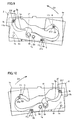
- the conventional thermal transfer printer comprises a metal chassis 101, a resin side plate 102, a platen roller 103, a paper feed roller 104, a platen roller bearing member 105 and a paper feed roller bearing member 106, as shown in Figs. 15 and 16.
- the chassis 101 has first and second side surfaces 101a and 101b opposed to each other.
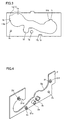
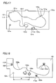
- the first side surface 101a of the chassis 101 is provided with an ink sheet cartridge receiving hole 101c for receiving an ink sheet cartridge (not shown), a long hole 101d and a positioning hole 101e, as shown in Figs. 16 and 17.
- the ink sheet cartridge receiving hole 101c is provided with a notch 101f receiving a paper feed roller bearing 102b of the side plate 102 described later. As shown in Fig.
- the first side surface 101a of the chassis 101 is provided with stepwise first and second notches 101g and 111g, stepwise first and second notches 101h and 111h and a rectangular notch 101i.
- a stop portion 121g is provided in the vicinity of the stepwise first and second notches 101g and 111g, while another stop portion 121h is provided in the vicinity of the stepwise first and second notches 101h and 111h.
- the second side surface 101b of the chassis 101 is provided with the platen roller bearing member 105 for supporting the platen roller 103 and the paper feed roller bearing member 106 for supporting the paper feed roller 104.
- a platen roller bearing 102a supporting the platen roller 103, the paper feed roller bearing 102b supporting the paper feed roller 104, a boss 102c for positioning the side plate 102 with respect to the first side surface 101a of the chassis 101 and hooked stop sections 102d, 102e and 102f for mounting the side plate 102 on the first side surface 101a of the chassis 101 are integrally provided on the side, mounted on the chassis 101, of the resin side plate 102, to protrude from the side plate 102.
- the stop sections 102d and 102e are so provided on the side plate 102 that hooks 112d and 112e vertically extend upward respectively.
- the stop section 102f is so provided on the side plate 102 that a hook 112f horizontally extends.
- the boss 102c for positioning the side plate 102 with respect to the first side surface 101a of the chassis 101 is provided on a position separated from the platen roller bearing 102a by a distance A, as shown in Fig. 18.
- the side plate 102 is further provided with a notch 102g for receiving the ink sheet cartridge (not shown) when the side plate 102 is mounted on the first side surface 101a of the chassis 101.
- the side plate 102 is parallelly brought into contact with the first side surface 101a of the chassis 101 in a state deviating from the first side surface 101a of the chassis 101 by a distance B, as shown in Fig. 19.
- the platen roller bearing 102a of the side plate 102 is inserted into the long hole 101d provided on the first side surface 101a of the chassis 101.
- the paper feed roller bearing 102b of the side plate 102 is inserted into the notch 101f provided on the first side surface 101a of the chassis 101.
- the stop sections 102d and 102e of the side plate 102 are inserted into the first notches 101g and 101h of the chassis 101 respectively, while the stop section 102f is inserted into the notch 101i.
- the boss 102c of the side plate 102 is not yet inserted into the positioning hole 101e provided on the first side surface 101a of the chassis 101.
- the side plate 102 is slid along arrow C (horizontal direction) shown in Fig. 19.
- the platen roller bearing 102a and the paper feed roller bearing 102b of the side plate 102 also move with the side plate 102.
- the positioning boss 102c of the side plate 102 is engaged with the positioning hole 101e provided on the first side surface 101a of the chassis 101.
- the stop sections 102d and 102e are moved from the first notches 101g and 101h to the second notches 111g and 111h respectively, to engage with the stop portions 121g and 121h respectively.
- the stop section 102f is also moved from the notch 101i to the stop portion 111i provided on the notch 101i to engage with the same, following the sliding of the side plate 102 along arrow C.
- the side plate 102 is mounted on the first side surface 101a of the chassis 101, while the positioning boss 102c of the side plate 102 engages with the positioning hole 101e provided on the first side surface 101a of the chassis 101, thereby positioning the side plate 102 with respect to the first side surface 101a of the chassis 101.
- the platen roller bearing 102a of the side plate 102 is not in contact with but separated from an end of the long hole 101d provided on the first side surface 101a of the chassis 101 in the sliding direction with a clearance D, as shown in Fig. 20.
- the paper feed roller bearing 102b is not in contact with but separated from an end of the notch 101f provided on the first side surface 101a of the chassis 101 in the sliding direction with a clearance E.
- the positioning boss 102c of the side plate 102 positions the side plate 102 in the sliding direction by engaging with the positioning hole 101e provided on the first side surface 101a of the chassis 101, to disadvantageously result in the clearance D between the platen roller bearing 102a and the end of the long hole 101d in the sliding direction. Therefore, it is difficult to improve positioning accuracy of the platen roller bearing 102a with respect to the first side surface 101a of the chassis 101 since the platen roller bearing 102a cannot be positioned by coming into contact with the end of the long hole 101d in the sliding direction.
- the present invention has been proposed in order to solve the aforementioned problem, and an object of the present invention is to provide an image generating apparatus capable of improving positional accuracy of a bearing of a side plate with respect to a chassis.
- An image generating apparatus comprises a chassis having a side surface mounted with a print head and a side plate, mounted on the side surface of the chassis, integrally provided with a bearing supporting a rotary shaft, while the side surface of the chassis is provided with a round hole receiving the bearing of the side plate, either the side plate or the side surface of the chassis is provided with a stop section for fixing the side plate to the side surface of the chassis, and either the side surface of the chassis or the side plate is provided with a stop portion engaging with the stop section through rotation of the side plate while the bearing of the side plate is inserted into the round hole provided on the side surface of the chassis.
- the "print head" has a function of printing not only characters but also pictures.
- the side surface of the chassis is provided with the round hole receiving the bearing of the side plate
- either the side plate or the side surface of the chassis is provided with the stop section for fixing the side plate to the side surface of the chassis and either the side surface of the chassis or the side plate is provided with the stop portion engaging with the stop section through rotation of the side plate while the bearing of the side plate is inserted into the round hole provided on the side surface of the chassis so that the side plate rotates about the bearing serving as the rotation center in the round hole provided on the side surface of the chassis, whereby the bearing serving as the rotation center neither horizontally nor vertically moves.
- the side plate is mounted on the side surface of the chassis with the stop section, therefore, the position of the bearing remains unmoved in the horizontal and vertical directions, whereby positioning accuracy of the bearing with respect to the side surface of the chassis can be improved.
- the bearing of the side plate preferably has a cylindrical form
- the round hole provided on the side surface of the chassis preferably includes a circular hole corresponding to the outer periphery of the cylindrical bearing.
- the side plate preferably further includes a projecting portion for positioning the side plate with respect to the side surface of the chassis, and the side surface of the chassis preferably further includes a recess portion engaging with the projecting portion of the side plate for positioning the side plate.
- the side plate is fixed to the side surface of the chassis on a prescribed rotational position, whereby the stop section and the stop portion can be inhibited from disengagement resulting from rotation of the side plate.
- the side surface of the chassis preferably includes a notch and the stop portion provided in the vicinity of the notch
- the side plate preferably includes a hooked stop section engaging with the stop portion, so that the side plate is brought into contact with the side surface of the chassis on a position rotated by a prescribed angle thereby inserting the hooked stop section of the side plate into the notch of the chassis and the side plate is thereafter rotated about the bearing of the side plate serving as the rotation center thereby engaging the hooked stop section of the side plate with the stop portion of the chassis.
- the side plate can be easily brought into contact with the side surface of the chassis in the state rotated by the prescribed angle despite the stop section, protruding from the side plate, provided for mounting the side plate on the side surface of the chassis, whereby the stop section of the side plate can be easily engaged with the stop portion on the side surface of the chassis by rotating the side plate about the bearing of the side plate serving as the rotation center from this state.
- the aforementioned image generating apparatus preferably further comprises a platen roller against which the print head is pressed, while the bearing provided on the side plate is preferably a platen roller bearing for supporting the rotary shaft of the platen roller. According to this structure, positional accuracy of the platen roller influencing printing accuracy can be so improved as to improve printing quality.
- the stop section of the side plate preferably includes a first stop section, a second stop section and a third stop section
- the notch of the chassis preferably includes a first notch, a second notch and a third notch receiving the first stop section, the second stop section and the third stop section respectively
- the stop portion of the chassis preferably includes a first stop portion, a second stop portion and a third stop portion so provided in the vicinity of the first notch, the second notch and the third notch as to engage with the first stop section, the second stop section and the third stop section respectively.
- the first, second and third stop sections engage with the first, second and third stop portions respectively for fixing the side plate to the side surface of the chassis on three positions, whereby the side plate can be strongly fixed to the side surface of the chassis.
- first stop portion and the second stop portion are preferably so provided as to vertically engage with the first stop section and the second stop section of the side plate respectively through rotation of the side plate.
- first and second stop sections can be easily engaged with the first and second stop portions provided on the side surface of the chassis respectively by rotating the side plate.
- the second notch is preferably provided on the bottom side of the side surface of the chassis, and the image generating apparatus preferably further comprises a fourth notch, coupled with the second notch, provided on the bottom surface of the chassis.
- the second stop section of the side plate inserted into the second notch can be inhibited from coming into contact with the bottom surface of the chassis due to the fourth notch provided on the bottom surface of the chassis, whereby the second stop section of the side plate can be easily inserted into the second notch and restriction of rotation of the side plate can be suppressed through the fourth notch.
- the side plate can be easily rotated about the bearing serving as the rotation center.
- the bearing, the projecting portion and the hooked stop section are preferably integrally formed on the side plate. According to this structure, the number of components can be inhibited from increase despite the bearing, the projecting portion and the hooked stop section provided on the side plate.
- the side plate is preferably molded from resin. According to this structure, the bearing, the projecting portion and the hooked stop section can be easily integrally formed on the side plate by resin molding.
- An image generating apparatus comprises a chassis having a side surface mounted with a print head, a side plate, mounted on the side surface of the chassis, integrally provided with a bearing supporting a rotary shaft and a platen roller against which the print head is pressed, while the bearing provided on the side plate is a platen roller bearing for supporting the rotary shaft of the platen roller, the side surface of the chassis is provided with a round hole receiving the bearing of the side plate, the side plate is provided with a hooked stop section for fixing the side plate to the side surface of the chassis and a projecting portion for positioning the side plate with respect to the side surface of the chassis, and the side surface of the chassis further includes a notch, a stop portion provided in the vicinity of the notch for engaging with the stop section when the side plate is rotated while the bearing of the side plate is inserted into the round hole of the side surface of the chassis and a recess portion engaging with the projecting portion of the side plate for positioning the side plate, so that the side plate is brought
- the side surface of the chassis is provided with the round hole receiving the bearing of the side plate
- the side plate is provided with the hooked stop section for fixing the side plate to the side surface of the chassis
- the side surface of the chassis is provided with the stop portion engaging with the stop section through rotation of the side plate while the bearing of the side plate is inserted into the round hole provided on the side surface of the chassis so that the side plate rotates about the bearing serving as the rotation center in the round hole provided on the side surface of the chassis, whereby the bearing serving as the rotation center neither horizontally nor vertically moves.
- the side plate When the side plate is mounted on the side surface of the chassis with the stop section, therefore, the position of the bearing remains unmoved in the horizontal and vertical directions, whereby positioning accuracy of the bearing with respect to the side surface of the chassis can be improved.
- the side plate includes the projecting portion for positioning the side plate with respect to the side surface of the chassis in the direction of rotation and the side surface of the chassis includes the recess portion engaging with the projecting portion of the side plate for positioning the side plate in the direction of rotation so that the side plate is fixed to the side surface of the chassis on a prescribed position of rotation, whereby the stop section and the stop portion can be inhibited from disengagement resulting from rotation of the side plate.
- the side surface of the chassis includes the notch and the stop portion provided in the vicinity of the notch
- the side plate includes the hooked stop section engaging with the stop portion and the hooked stop section of the side plate is engaged with the stop portion of the chassis by bringing the side plate into contact with the side surface of the chassis on the position rotated by the prescribed angle thereby inserting the hooked stop section of the side plate into the notch of the chassis and thereafter rotating the side plate about the bearing of the side plate serving as the rotation center so that the side plate can be easily brought into contact with the side surface of the chassis in the state rotated by the prescribed angle despite the stop section, protruding from the side plate, provided for mounting the side plate on the side surface of the chassis, whereby the stop section of the side plate can be easily engaged with the stop portion provided on the side surface of the chassis by rotating the side plate about the bearing of the side plate serving as the rotation center from this state.
- the bearing provided on the side plate is so employed as the platen roller bearing for supporting the rotary shaft of the platen roller that positional accuracy of the plate
- the bearing of the side plate preferably has a cylindrical form
- the round hole provided on the side surface of the chassis preferably includes a circular hole corresponding to the outer periphery of the cylindrical bearing.
- the stop section of the side plate preferably includes a first stop section, a second stop section and a third stop section
- the notch of the chassis preferably includes a first notch, a second notch and a third notch receiving the first stop section, the second stop section and the third stop section respectively
- the stop portion of the chassis preferably includes a first stop portion, a second stop portion and a third stop portion so provided in the vicinity of the first notch, the second notch and the third notch as to engage with the first stop section, the second stop section and the third stop section respectively.
- the first, second and third stop sections engage with the first, second and third stop portions respectively for fixing the side plate to the side surface of the chassis on three positions, whereby the side plate can be more strongly fixed to the side surface of the chassis as compared with a case of fixing the side plate to the side surface of the chassis on less than three positions.
- first stop portion and the second stop portion are preferably so provided as to vertically engage with the first stop section and the second stop section of the side plate respectively through rotation of the side plate.
- first and second stop sections can be easily engaged with the first and second stop portions provided on the side surface of the chassis respectively by rotating the side plate.
- the second notch is preferably provided on the bottom side of the side surface of the chassis, and the image generating apparatus preferably further comprises a fourth notch, coupled with the second notch, provided on the bottom surface of the chassis.
- the second stop section of the side plate inserted into the second notch can be inhibited from coming into contact with the bottom surface of the chassis due to the fourth notch provided on the bottom surface of the chassis, whereby the second stop section of the side plate can be easily inserted into the second notch and restriction of rotation of the side plate can be suppressed through the fourth notch.
- the side plate can be easily rotated about the bearing serving as the rotation center.
- the bearing, the projecting portion and the hooked stop section are preferably integrally formed on the side plate. According to this structure, the number of components can be inhibited from increase despite the bearing, the projecting portion and the hooked stop section provided on the side plate.
- the side plate is preferably molded from resin. According to this structure, the bearing, the projecting portion and the hooked stop section can be easily integrally formed on the side plate by resin molding.
- thermal transfer printer The structure of a thermal transfer printer according to this embodiment is described with reference to Figs. 1 to 8.
- the embodiment of the present invention is applied to the thermal transfer printer, i.e., an exemplary image generating apparatus.
- the thermal transfer printer comprises a metal chassis 1, a resin side plate 2 mounted on a side surface of the chassis 1, a print head 3 for printing characters (pictures), a platen roller 4 opposed to the print head 3, a paper feed roller 5, a platen roller bearing member 6 and a paper feed roller bearing member 7.
- the chassis 1 has first and second side surfaces 1a and 1b opposed to each other and a bottom surface 1c coupling the first and second side surfaces 1a and 1b with each other.
- the first and second side surfaces 1a and 1b of the chassis 1 are provided with support holes 1d for rotatably supporting the print head 3 respectively.
- the first side surface 1a is provided with an ink sheet cartridge receiving hole 1e for receiving an ink sheet cartridge (not shown), as shown in Figs. 3 and 6.
- the ink sheet cartridge receiving hole 1e is provided with a notch 1f receiving a paper feed roller bearing 2b of the side plate 2.
- the platen roller bearing member 6 and the paper feed roller bearing member 7 for supporting the platen roller 4 and the paper feed roller 5 respectively are mounted on the second side surface 1b.
- the first side surface 1a of the chassis 1 is an example of the "side surface of the chassis" in the present invention.
- a round hole 1g and a rotational direction positioning hole 1h are provided on the first side surface 1a of the chassis 1.
- the round hole 1g has a size corresponding to the outer periphery of a cylindrical platen roller bearing 2a described later.
- the hole 1h is an example of the "recess portion" in the present invention.
- rectangular notches 1i, 1j and 1k are provided on the first side surface 1a of the chassis 1, as shown in Fig. 3. Stop portions 11i, 11j and 11k are provided in the vicinity of the rectangular notches 1i, 1j and 1k for engaging with stop sections 2d, 2e an 2f of the side plate 2 described later respectively. As shown in Fig. 8, a notch 1m coupled with the notch 1j close to the bottom surface 1c is provided on the bottom surface 1c of the chassis 1.
- the notches 1i, 1j and 1k are examples of the “first notch”, the “second notch” and the “third notch” in the present invention respectively, and the stop portions 11i, 11j and 11k are examples o the "first stop portion”, the “second stop portion” and the “third stop portion” in the present invention respectively.
- the notch 1m is an example of the "fourth notch” in the present invention.
- the cylindrical platen roller bearing 2a supporting the platen roller 4, the paper feed roller bearing 2b supporting the paper feed roller 5, a boss 2c for positioning the side plate 2 with respect to the first side surface 1a of the chassis 1 and hooked stop sections 2d, 2e and 2f for mounting the side plate 2 on the first side surface 1a of the chassis 1 are integrally provided on the side of the resin side plate 2 mounted on the chassis 1, to protrude from the side plate 2.
- the boss 2c is an example of the "projecting portion” in the present invention, and the stop sections 2d, 2e and 2f are examples of the "first stop section", the "second stop section” and the "third stop section” in the present invention respectively.
- the stop sections 2d and 2e are so provided on the side plate 2 that hooks 21d and 21e thereof vertically extend upward respectively, as shown in Figs. 4 and 5. Thus, the hooks 21d and 21e vertically engage with the stop portions 11i and 11j respectively upon rotation of the side plate 2.
- the stop section 2f is so provided on the side plate 2 that a hook 21f thereof horizontally extends.
- the side plate 2 is further provided with a notch 2g for receiving the ink sheet cartridge (not shown) when the side plate 2 is mounted on the first side surface 1a of the chassis 1.
- the print head 3 has a pair of support shafts 3a, a head portion 3b opposed to the platen roller 4 and a pair of arms 3c coupling the support shafts 3a and the head portion 3b with each other.
- the print head 3 is rotatable about the support shafts 3a.
- the pair of support shafts 3a of the print head 3 are rotatably mounted on the first and second side surfaces 1a and 1b respectively.
- the thermal transfer printer prints characters (pictures) by thermally transferring an ink sheet (not shown) to paper (not shown) with the print head 3 while holding the paper and the ink sheet between the platen roller 4 and the head portion 3b.
- first ends of the platen roller 4 and the paper feed roller 5 are rotatably supported on the platen roller bearing 2a and the paper feed roller bearing 2b of the side plate 2 mounted on the first side surface 1a of the chassis 1 respectively.
- Second ends of the platen roller 4 and the paper feed roller 5 are rotatably supported on the platen roller bearing member 6 and the paper feed roller bearing member 7 mounted on the second side surface 1b of the chassis 1 respectively (see Fig. 2).
- the side plate 2 is brought into contact with the first side surface 1a of the chassis 1 in a state inclined by a prescribed angle ⁇ with respect to the first side surface 1a, as shown in Figs. 6, 9 and 10. At this time, the platen roller bearing 2a of the side plate 2 is inserted into the round hole 1g of the first side surface 1a of the chassis 1. Further, the paper feed roller bearing 2b of the side plate 2 is inserted into the notch 1f of the first side surface 1a of the chassis 1.
- the stop sections 2d and 2f of the side plate 2 are inserted into the notches 1i and 1k provided on the first side surface 1a of the chassis 1 respectively. Further, the stop section 2e is inserted into the notch 1j provided on the first side surface 1a of the chassis 1 and the notch 1m, provided on the bottom surface 1c, coupled with the notch 1j.
- the side plate 2 comes into contact with the first side surface 1a of the chassis 1 in the state inclined by the prescribed angle ⁇ in the direction of rotation. In this state, the boss 2c of the side pale 2 is not yet inserted into the positioning hole 1h provided on the first side surface 1a of the chassis 1.
- the side plate 2 is rotated about the platen roller bearing 2a, serving as the rotation center, provided thereon along arrow C1, as shown in Fig. 9.
- the positioning boss 2c provided on the side plate 2 engages with the positioning hole 1h provided on the first side surface 1a of the chassis 1.
- the stop sections 2d, 2e and 2f provided on the side plate 2 engage with the stop portions 11i, 11j and 11k provided on the first side surface 1a of the chassis 1 respectively simultaneously with the engagement between the positioning boss 2c and the hole 1h, as shown in Figs. 8, 11 and 12.
- the hooked stop sections 2d, 2e and 2f of the side plate 2 engage with the stop portions 11i, 11j and 11k provided on the first side surface 1a of the chassis 1 in a hooked manner, as shown in Figs. 13 and 14.
- the side plate 2 is mounted on the first side surface 1a of the chassis 1.
- the first side surface 1a of the chassis 1 is provided with the round hole 1g receiving the platen roller bearing 2a of the side plate 2
- the side plate 2 is provided with the hooked stop sections 2d, 2e and 2f for fixing the side plate 2 to the first side surface 1a of the chassis 1
- the first side surface 1a of the chassis 1 is further provided with the stop portions 11i, 11j and 11k for engaging with the stop sections 2d, 2e and 2f upon rotation of the side plate 2 having the platen roller bearing 2a inserted into the round hole 1g of the first side surface 1a so that the side plate 2 is rotated about the platen roller bearing 2a serving as the rotation center in the round hole 1g provided on the first side surface 1a of the chassis 1, whereby the platen roller bearing 2a serving as the rotation center neither horizontally nor vertically moves.
- the side plate 2 includes the boss 2c for positioning the side plate 2 with respect to the first side surface 1a of the chassis 1 I the direction of rotation and the first side surface 1a of eth chassis 1 includes the positioning hole 1h for engaging with the boss 2c of the side plate 2 thereby positioning the side plate 2 in the direction of rotation so that the side plate 2 is fixed to the first side surface 1a of the chassis 1 on a prescribed rotational position, whereby the stop sections 2d, 2e and 2f and the stop portions 11i, 11j and 11k can be inhibited from disengagement resulting from rotation of the side plate 2.
- the first side surface 1a of the chassis 1 includes the notches 1i, 1j and 1k and the stop portions 11i, 11j and 11k provided in the vicinity of the notches 1i, 1j and 1k respectively
- the side plate 2 includes the hooked stop sections 2d, 2e and 2f engaging with the stop portions 11i, 11j and 11k respectively and the side plate 2 is brought into contact with the first side surface 1a of the chassis 1 on the position rotated by the prescribed angle ⁇ for inserting the hooked stop sections 2d, 2e and 2f of the side plate 2 into the notches 1i, 1j and 1k of the chassis 1 respectively while the side plate 2 is thereafter rotated about the platen roller bearing 2a of the side plate 2 serving as the rotation center for engaging the hooked stop sections 2d, 2e and 2f of the side plate 2 with the stop portions 11i, 11j and 11k of the chassis 1 respectively so that the side plate 2 can be easily brought into contact with the first side surface 1a of the chassis 1 in the state rotated by the prescribed angle ⁇ despite
- the present invention is not restricted to this but is also applicable to another image generating apparatus other than the thermal transfer printer, so far as the same comprises a side plate on a side surface of a chassis.
- the present invention is not restricted to this but a round hole receiving the paper feed roller bearing may alternatively be provided on the first side surface of the chassis for inserting the paper feed roller bearing into this hole and rotating the side plate about the paper feed roller bearing serving as the rotation center thereby mounting the side plate on the first side surface of the chassis.
- the present invention is not restricted to this but a positioning hole (recess portion) and a positioning boss (projecting portion) inserted into this hole may alternatively be provided on the side plate and the first side surface of the chassis respectively.
- the present invention is not restricted to this but the notches may have a shape other than the rectangular shape, so far as the same have similar functions.
- the present invention is not restricted to this but the stop sections may alternatively have a shape other than the hooked shape, so far as the same can be stopped on the first side surface of the chassis for mounting the side plate on the first side surface.
- the stop sections may be formed by notched round rods.
Landscapes
- Engineering & Computer Science (AREA)
- Multimedia (AREA)
- Signal Processing (AREA)
- Handling Of Sheets (AREA)
- Electronic Switches (AREA)
- Electrophotography Configuration And Component (AREA)
Applications Claiming Priority (1)
| Application Number | Priority Date | Filing Date | Title |
|---|---|---|---|
| JP2005165081A JP4806971B2 (ja) | 2005-06-06 | 2005-06-06 | 画像形成装置 |
Publications (2)
| Publication Number | Publication Date |
|---|---|
| EP1732304A1 true EP1732304A1 (fr) | 2006-12-13 |
| EP1732304B1 EP1732304B1 (fr) | 2007-10-24 |
Family
ID=36577553
Family Applications (1)
| Application Number | Title | Priority Date | Filing Date |
|---|---|---|---|
| EP06251518A Expired - Fee Related EP1732304B1 (fr) | 2005-06-06 | 2006-03-22 | Appareil de génération d'images avec engagement rotatif êntre la plaque latérale et le chassis |
Country Status (4)
| Country | Link |
|---|---|
| US (1) | US7453483B2 (fr) |
| EP (1) | EP1732304B1 (fr) |
| JP (1) | JP4806971B2 (fr) |
| DE (1) | DE602006000181T2 (fr) |
Families Citing this family (5)
| Publication number | Priority date | Publication date | Assignee | Title |
|---|---|---|---|---|
| US20080089731A1 (en) * | 2006-10-12 | 2008-04-17 | Ezra Szoke | Method and apparatus for using dye-diffusion thermal printing |
| JP2008188961A (ja) * | 2007-02-08 | 2008-08-21 | Funai Electric Co Ltd | 画像形成装置 |
| JP5142935B2 (ja) * | 2008-10-10 | 2013-02-13 | 株式会社サトー知識財産研究所 | ローラ装置 |
| JP5432050B2 (ja) * | 2009-09-17 | 2014-03-05 | 東芝テック株式会社 | ポータブルプリンタ |
| JP5459242B2 (ja) * | 2011-03-08 | 2014-04-02 | ブラザー工業株式会社 | 軸受装置、ドラムユニットおよび画像形成装置 |
Citations (3)
| Publication number | Priority date | Publication date | Assignee | Title |
|---|---|---|---|---|
| JPH0360471U (fr) * | 1989-10-13 | 1991-06-13 | ||
| US5917617A (en) * | 1995-12-20 | 1999-06-29 | Matsushita Graphic Communications, Inc. | Communication apparatus for transmitting and receiving information |
| US20020021343A1 (en) * | 2000-07-21 | 2002-02-21 | Haruo Uchida | Recording apparatus with modular housing components |
Family Cites Families (11)
| Publication number | Priority date | Publication date | Assignee | Title |
|---|---|---|---|---|
| JPH0360471A (ja) * | 1989-07-25 | 1991-03-15 | Alps Electric Co Ltd | 積層セラミックスの製造方法 |
| JPH0698548B2 (ja) * | 1989-07-27 | 1994-12-07 | 株式会社大長鉄工 | 加工機用板材料搬入出方法 |
| JPH0450034Y2 (fr) | 1989-10-17 | 1992-11-25 | ||
| JP2962938B2 (ja) * | 1992-07-16 | 1999-10-12 | シャープ株式会社 | 感光体ドラムカートリッジおよびこれを利用した画像形成装置 |
| JPH0768810A (ja) * | 1993-06-17 | 1995-03-14 | Ricoh Co Ltd | 熱転写式記録装置 |
| JP3693069B2 (ja) * | 1995-10-06 | 2005-09-07 | ソニー株式会社 | インクリボンを用いたプリンター |
| JP3385888B2 (ja) * | 1996-12-25 | 2003-03-10 | 松下電器産業株式会社 | 感熱紙の印字装置 |
| JPH11268315A (ja) | 1998-03-26 | 1999-10-05 | Alps Electric Co Ltd | ラインプリンタ |
| JP4635327B2 (ja) * | 2000-11-13 | 2011-02-23 | ブラザー工業株式会社 | 画像形成装置 |
| JP3631155B2 (ja) * | 2001-03-16 | 2005-03-23 | キヤノン株式会社 | プロセスカートリッジ着脱機構 |
| JP2007326258A (ja) * | 2006-06-07 | 2007-12-20 | Funai Electric Co Ltd | 画像形成装置 |
-
2005
- 2005-06-06 JP JP2005165081A patent/JP4806971B2/ja not_active Expired - Fee Related
-
2006
- 2006-03-22 EP EP06251518A patent/EP1732304B1/fr not_active Expired - Fee Related
- 2006-03-22 DE DE602006000181T patent/DE602006000181T2/de not_active Expired - Lifetime
- 2006-03-28 US US11/390,165 patent/US7453483B2/en not_active Expired - Fee Related
Patent Citations (3)
| Publication number | Priority date | Publication date | Assignee | Title |
|---|---|---|---|---|
| JPH0360471U (fr) * | 1989-10-13 | 1991-06-13 | ||
| US5917617A (en) * | 1995-12-20 | 1999-06-29 | Matsushita Graphic Communications, Inc. | Communication apparatus for transmitting and receiving information |
| US20020021343A1 (en) * | 2000-07-21 | 2002-02-21 | Haruo Uchida | Recording apparatus with modular housing components |
Also Published As
| Publication number | Publication date |
|---|---|
| JP2006337890A (ja) | 2006-12-14 |
| DE602006000181D1 (de) | 2007-12-06 |
| US7453483B2 (en) | 2008-11-18 |
| US20060274380A1 (en) | 2006-12-07 |
| DE602006000181T2 (de) | 2008-08-07 |
| EP1732304B1 (fr) | 2007-10-24 |
| JP4806971B2 (ja) | 2011-11-02 |
Similar Documents
| Publication | Publication Date | Title |
|---|---|---|
| EP1732304B1 (fr) | Appareil de génération d'images avec engagement rotatif êntre la plaque latérale et le chassis | |
| EP2070707B1 (fr) | Dispositif d'impression | |
| JPH10278322A (ja) | 感熱記録装置 | |
| US7959367B2 (en) | Image generating apparatus | |
| EP1864821B1 (fr) | Appareil de génération d'images | |
| JP2542907Y2 (ja) | 軸受装置 | |
| JP4006700B2 (ja) | 熱転写プリンタ | |
| JP4518690B2 (ja) | 小型携帯プリンタ | |
| JP4475755B2 (ja) | 着脱自在なサーマルヘッドを備えるプリンタ装置 | |
| JP2001088975A (ja) | シート搬送装置 | |
| EP1757460B1 (fr) | Dispositif de génération d'image | |
| US7495685B2 (en) | Image generating apparatus | |
| US7256807B2 (en) | Thermal printer | |
| JP4735433B2 (ja) | 画像形成装置 | |
| JP2999922B2 (ja) | ヘッド駆動装置 | |
| JP2001192154A (ja) | ラベルプリンタの用紙供給装置 | |
| US8434953B2 (en) | Thermal print head mounting apparatus | |
| JP3563001B2 (ja) | 熱転写プリンタ | |
| JP3053956U (ja) | ガイドシャフト固定装置 | |
| JPS6341159A (ja) | ライン走査型感熱記録装置のサ−マルヘツド位置決め機構 | |
| JPH0642192U (ja) | プリンタの印字ヘッドギャップ調整装置 | |
| EP1892111A1 (fr) | Appareil de génération d'images | |
| JP2005186450A (ja) | 熱転写プリンタおよび画像形成装置 | |
| JP4336571B2 (ja) | サーマルヘッド圧接機構およびこれを用いたサーマルプリンタ | |
| JPH0413179Y2 (fr) |
Legal Events
| Date | Code | Title | Description |
|---|---|---|---|
| PUAI | Public reference made under article 153(3) epc to a published international application that has entered the european phase |
Free format text: ORIGINAL CODE: 0009012 |
|
| AK | Designated contracting states |
Kind code of ref document: A1 Designated state(s): AT BE BG CH CY CZ DE DK EE ES FI FR GB GR HU IE IS IT LI LT LU LV MC NL PL PT RO SE SI SK TR |
|
| AX | Request for extension of the european patent |
Extension state: AL BA HR MK YU |
|
| 17P | Request for examination filed |
Effective date: 20070125 |
|
| 17Q | First examination report despatched |
Effective date: 20070223 |
|
| GRAP | Despatch of communication of intention to grant a patent |
Free format text: ORIGINAL CODE: EPIDOSNIGR1 |
|
| AKX | Designation fees paid |
Designated state(s): DE GB |
|
| GRAS | Grant fee paid |
Free format text: ORIGINAL CODE: EPIDOSNIGR3 |
|
| GRAA | (expected) grant |
Free format text: ORIGINAL CODE: 0009210 |
|
| AK | Designated contracting states |
Kind code of ref document: B1 Designated state(s): DE GB |
|
| REG | Reference to a national code |
Ref country code: GB Ref legal event code: FG4D |
|
| REF | Corresponds to: |
Ref document number: 602006000181 Country of ref document: DE Date of ref document: 20071206 Kind code of ref document: P |
|
| PLBE | No opposition filed within time limit |
Free format text: ORIGINAL CODE: 0009261 |
|
| STAA | Information on the status of an ep patent application or granted ep patent |
Free format text: STATUS: NO OPPOSITION FILED WITHIN TIME LIMIT |
|
| 26N | No opposition filed |
Effective date: 20080725 |
|
| PGFP | Annual fee paid to national office [announced via postgrant information from national office to epo] |
Ref country code: DE Payment date: 20150317 Year of fee payment: 10 |
|
| PGFP | Annual fee paid to national office [announced via postgrant information from national office to epo] |
Ref country code: GB Payment date: 20150318 Year of fee payment: 10 |
|
| REG | Reference to a national code |
Ref country code: DE Ref legal event code: R119 Ref document number: 602006000181 Country of ref document: DE |
|
| GBPC | Gb: european patent ceased through non-payment of renewal fee |
Effective date: 20160322 |
|
| PG25 | Lapsed in a contracting state [announced via postgrant information from national office to epo] |
Ref country code: DE Free format text: LAPSE BECAUSE OF NON-PAYMENT OF DUE FEES Effective date: 20161001 Ref country code: GB Free format text: LAPSE BECAUSE OF NON-PAYMENT OF DUE FEES Effective date: 20160322 |