EP1733202B1 - System and method for extracting gases from a process environment - Google Patents
System and method for extracting gases from a process environment Download PDFInfo
- Publication number
- EP1733202B1 EP1733202B1 EP05718660A EP05718660A EP1733202B1 EP 1733202 B1 EP1733202 B1 EP 1733202B1 EP 05718660 A EP05718660 A EP 05718660A EP 05718660 A EP05718660 A EP 05718660A EP 1733202 B1 EP1733202 B1 EP 1733202B1
- Authority
- EP
- European Patent Office
- Prior art keywords
- tubular element
- gaseous fluid
- probe
- process environment
- gas
- Prior art date
- Legal status (The legal status is an assumption and is not a legal conclusion. Google has not performed a legal analysis and makes no representation as to the accuracy of the status listed.)
- Expired - Lifetime
Links
- 238000000034 method Methods 0.000 title claims abstract description 45
- 230000008569 process Effects 0.000 title claims abstract description 38
- 239000007789 gas Substances 0.000 title description 65
- 239000000523 sample Substances 0.000 claims abstract description 60
- 239000012530 fluid Substances 0.000 claims abstract description 42
- 239000000428 dust Substances 0.000 claims description 15
- 238000001816 cooling Methods 0.000 claims description 14
- 238000004458 analytical method Methods 0.000 claims description 11
- 238000011144 upstream manufacturing Methods 0.000 claims description 6
- 238000011001 backwashing Methods 0.000 claims description 4
- 238000001035 drying Methods 0.000 claims description 4
- 238000002347 injection Methods 0.000 claims description 4
- 239000007924 injection Substances 0.000 claims description 4
- 239000003795 chemical substances by application Substances 0.000 claims description 2
- 239000013256 coordination polymer Substances 0.000 claims description 2
- 238000012544 monitoring process Methods 0.000 claims description 2
- 238000009825 accumulation Methods 0.000 claims 1
- 230000004913 activation Effects 0.000 claims 1
- 238000000605 extraction Methods 0.000 abstract description 9
- XLYOFNOQVPJJNP-UHFFFAOYSA-N water Substances O XLYOFNOQVPJJNP-UHFFFAOYSA-N 0.000 description 13
- 238000004140 cleaning Methods 0.000 description 12
- 239000002253 acid Substances 0.000 description 8
- 150000007513 acids Chemical class 0.000 description 6
- 230000004888 barrier function Effects 0.000 description 4
- 239000000498 cooling water Substances 0.000 description 4
- 239000000446 fuel Substances 0.000 description 4
- 239000000463 material Substances 0.000 description 4
- 238000005406 washing Methods 0.000 description 4
- 238000009434 installation Methods 0.000 description 3
- 238000012423 maintenance Methods 0.000 description 3
- 238000007726 management method Methods 0.000 description 3
- 238000012856 packing Methods 0.000 description 3
- 230000009467 reduction Effects 0.000 description 3
- 230000001458 anti-acid effect Effects 0.000 description 2
- 230000008901 benefit Effects 0.000 description 2
- 230000015572 biosynthetic process Effects 0.000 description 2
- 239000004568 cement Substances 0.000 description 2
- 239000000567 combustion gas Substances 0.000 description 2
- 238000009833 condensation Methods 0.000 description 2
- 230000005494 condensation Effects 0.000 description 2
- 239000002826 coolant Substances 0.000 description 2
- 230000008878 coupling Effects 0.000 description 2
- 238000010168 coupling process Methods 0.000 description 2
- 238000005859 coupling reaction Methods 0.000 description 2
- 230000000694 effects Effects 0.000 description 2
- 238000001914 filtration Methods 0.000 description 2
- 238000004868 gas analysis Methods 0.000 description 2
- 230000004044 response Effects 0.000 description 2
- 238000003860 storage Methods 0.000 description 2
- 239000000126 substance Substances 0.000 description 2
- OKTJSMMVPCPJKN-UHFFFAOYSA-N Carbon Chemical compound [C] OKTJSMMVPCPJKN-UHFFFAOYSA-N 0.000 description 1
- 229910000831 Steel Inorganic materials 0.000 description 1
- 230000003213 activating effect Effects 0.000 description 1
- 230000006978 adaptation Effects 0.000 description 1
- 230000004075 alteration Effects 0.000 description 1
- 229940069428 antacid Drugs 0.000 description 1
- 239000003159 antacid agent Substances 0.000 description 1
- 230000005587 bubbling Effects 0.000 description 1
- 229910052799 carbon Inorganic materials 0.000 description 1
- 238000001311 chemical methods and process Methods 0.000 description 1
- 238000002485 combustion reaction Methods 0.000 description 1
- 238000011109 contamination Methods 0.000 description 1
- 238000005260 corrosion Methods 0.000 description 1
- 230000007797 corrosion Effects 0.000 description 1
- 125000004122 cyclic group Chemical group 0.000 description 1
- 230000001419 dependent effect Effects 0.000 description 1
- 238000010586 diagram Methods 0.000 description 1
- 238000007599 discharging Methods 0.000 description 1
- 230000007717 exclusion Effects 0.000 description 1
- 239000002360 explosive Substances 0.000 description 1
- 238000000227 grinding Methods 0.000 description 1
- 239000012535 impurity Substances 0.000 description 1
- 238000007689 inspection Methods 0.000 description 1
- 230000001788 irregular Effects 0.000 description 1
- 238000004519 manufacturing process Methods 0.000 description 1
- 239000000843 powder Substances 0.000 description 1
- 238000001556 precipitation Methods 0.000 description 1
- 238000011160 research Methods 0.000 description 1
- 238000007789 sealing Methods 0.000 description 1
- 239000007921 spray Substances 0.000 description 1
- 238000005507 spraying Methods 0.000 description 1
- 230000003019 stabilising effect Effects 0.000 description 1
- 239000010959 steel Substances 0.000 description 1
- 238000010408 sweeping Methods 0.000 description 1
- 239000002699 waste material Substances 0.000 description 1
Images


Classifications
-
- G—PHYSICS
- G01—MEASURING; TESTING
- G01N—INVESTIGATING OR ANALYSING MATERIALS BY DETERMINING THEIR CHEMICAL OR PHYSICAL PROPERTIES
- G01N1/00—Sampling; Preparing specimens for investigation
- G01N1/02—Devices for withdrawing samples
- G01N1/22—Devices for withdrawing samples in the gaseous state
-
- G—PHYSICS
- G01—MEASURING; TESTING
- G01N—INVESTIGATING OR ANALYSING MATERIALS BY DETERMINING THEIR CHEMICAL OR PHYSICAL PROPERTIES
- G01N1/00—Sampling; Preparing specimens for investigation
- G01N1/02—Devices for withdrawing samples
- G01N1/22—Devices for withdrawing samples in the gaseous state
- G01N1/2247—Sampling from a flowing stream of gas
-
- G—PHYSICS
- G01—MEASURING; TESTING
- G01N—INVESTIGATING OR ANALYSING MATERIALS BY DETERMINING THEIR CHEMICAL OR PHYSICAL PROPERTIES
- G01N1/00—Sampling; Preparing specimens for investigation
- G01N1/02—Devices for withdrawing samples
- G01N1/22—Devices for withdrawing samples in the gaseous state
- G01N1/2247—Sampling from a flowing stream of gas
- G01N1/2258—Sampling from a flowing stream of gas in a stack or chimney
-
- G—PHYSICS
- G01—MEASURING; TESTING
- G01N—INVESTIGATING OR ANALYSING MATERIALS BY DETERMINING THEIR CHEMICAL OR PHYSICAL PROPERTIES
- G01N1/00—Sampling; Preparing specimens for investigation
- G01N1/02—Devices for withdrawing samples
- G01N1/22—Devices for withdrawing samples in the gaseous state
- G01N1/24—Suction devices
-
- G—PHYSICS
- G01—MEASURING; TESTING
- G01N—INVESTIGATING OR ANALYSING MATERIALS BY DETERMINING THEIR CHEMICAL OR PHYSICAL PROPERTIES
- G01N1/00—Sampling; Preparing specimens for investigation
- G01N1/02—Devices for withdrawing samples
- G01N1/22—Devices for withdrawing samples in the gaseous state
- G01N2001/2285—Details of probe structures
Definitions
- the present invention relates in general to systems for the regulation and control of chemical processes which involve the production of gas, for example processes of combustion in cement furnaces.
- Systems are known for the extraction of gases from a furnace, provided with probes to be mounted within the furnace, in which the gases extracted are conveyed to analyser devices.
- the probes further have serious problems of blockage of the gas aspiration tube, which make operation unreliable.
- GB-A-1 445 061 , US-A-4 336 722 , DE 44 30 378 A1 , CA-A1-2 196 846 and US-A-3 938 390 disclose systems for extracting a gaseous fluid to be analysed from a process environment.
- GB-A-1 445 061 discloses a system for extracting a gaseous fluid to be analyzed from a process environment, comprising:
- the system of GB-A-1 445 061 solves the problem of preventing the clogging of the probe only in a limited way.
- one object of the invention is that of providing a system for extracting a gaseous fluid to be analysed from a process environment which is able to prevent or at least reduce the occurrence of clogging of the probe, that is to say to guarantee continuity of use without continual maintenance interventions (with improvements in the gas extraction system and continuity and reliability of the analysis).
- Another object of the invention is a method for extracting and re-injecting a gaseous fluid from and to a process environment having the characteristics defined in Claim 12.
- This system by co-operating with the probe according to the invention, lowers the dust (filter less stressed), makes it possible to dry the gas (no clogging and no origination of acids) and is self cleaning without the aid of compressed air but by utilising the same process gas (continuity of analysis since it is not altered).
- furnace in any conditions of use; temperature, dust level, steam, acid etc
- fuel even alternative/waste disposal fuel
- the probe has been designed for cement furnaces but can be used in process environments in industries of different type; steelworks, thermo-electric plants, chemical/petrochemical industries, carbon grinding and storage, incinerators, explosive powder storage silos, that is to say in all those sectors where it is required to extract gas for subsequent analysis (furnaces, silos, chimneys, pipework etc).
- the salient characteristic of the probe and the system according to the invention is the reduced necessity for maintenance. This is achieved by avoiding aspiration of dust/condensate, and thanks to the violent and continuous spraying of compressed gas ensured by the compressor.
- the filter has a long life since it is self-cleaning by means of the powerful counter current flow of gas during the rapid discharge for probe cleaning.
- the probe is easy to install in a short time, not requiring a great deal of work for adaptation of the existing system to be able to connect it. Moreover, it does not require a great deal of care in research for the optimum positioning in the furnace (the minimum dust point etc).
- the probe For use at high temperatures the probe is water-cooled. It has an anti-condensate interspace for decoupling the hot zone (gas circuit) from the cold zone (cooling water jacket), permitting the gas extracted to maintain its temperature.
- This arrangement avoids the formation of condensate in the inner wall of the aspiration tube, thereby minimising clogging of the dust.
- the two chambers for gas and cooling can be separated because they are coupled with flanges. This makes is possible to remove only the gas circuit from the furnace (for a possible inspection and cleaning, even with the furnace in operation) leaving only the cooling system fixed to the furnace.
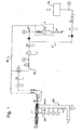
- a system for the extraction of gas from a process environment for example a furnace (not illustrated) comprises a probe S, a compressor C, a piping 20 for supply of cooling water to the probe S and a piping 30 for the discharge of this water from the probe S, a piping 40 for aspiration of gas from the probe S and a piping 50 for the re-injection of the gas to the probe S/process environment.
- the system is supplied with an electric voltage for the compressor C and solenoid valves EV1G, EV2G, a fluid, for example water, for cooling the probe S, and a compressed fluid, for example air, for the solenoid valve actuators EV1G, EV2G.
- a low temperature refrigerator with closed circuit water could be used for the cooling system.
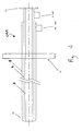
- the probe S in its essential form comprises two concentric tubes 1 and 2, for example in AISI304 steel, but it is possible to utilise material more suitable to high temperatures and resistant to acid corrosion.
- the outer tube 2 is dedicated to the aspiration of gas, the inner tube 1 is the gas delivery.
- This probe S is usable in low temperature environments. To utilise it with high temperatures it is necessary to provide it with a water-cooling jacket (illustrated in Figure 4 ).
- the probe S is shown provided with a gas circulation chamber and a water-cooling jacket CRA.
- This version (with water cooling) is for high temperatures and comprises five concentric tubes 1, 2, 3, 4, 5.
- the probe S is fitted to and fixed in the wall of the furnace by means of a support flange FS.
- the probe head TS is fitted with a protection cone CP acting as a first barrier against the ingress of impurities into the probe.
- the three outermost tubes 3, 4, 5 constitute the cooling chamber CRA through which flows water (fixed solidly to the furnace by means of the flange FS to permit its fitting and fixing).
- the space between the innermost tube 3 and the intermediate tube 4 of the jacket CRA is connected to the water supply piping 20 by means of a water filter FA for cooling water, and the space between the intermediate tube 4 and the outermost tube 5 of the jacket CRA is connected to the water discharge piping 30 by means of a manual valve VMA for regulation of the rate of flow of cooling water.
- the said spaces are fluidly connected at the head TS of the probe.
- Upstream of the supply piping 20 and downstream of the discharge piping 30 are disposed respective coolant water relief valves VSA.
- In the discharge piping 30 are, moreover, disposed a sensor Ta for control of the water temperature, a sensor Pa for control of the water pressure and a sensor Fa for control of the water flow.
- the two innermost tubes 1 and 2 constitute the gas extraction probe true and proper (fitted and coupled to the coolant jacket by means of flange FL to allow its removal in a simple and rapid manner, even with the installation in operation - see Figures 2 and 3 ).
- the coupling of the two chambers gives rise to an interspace IN, blind at the probe bottom (outer furnace side) and open at the head TS (inner furnace size) that is to say it is licked by the gas.
- This avoids the formation of condensation within the gas aspiration tube 2 (second tube) and makes it possible for the gas withdrawn not to be excessively cooled.
- the gas is aspirated into the chamber CA constituted by the first and second tube 1, 2 and injected again into the interior of the furnace through of the concentric central tube (first tube 1), by means of a compressor C.
- the furnace side end UG of the central tube is throttled so that the ejected gas is compressed.
- this end has a nozzle.
- the same central tube 1 can be realised as a capillary tube for injecting the gas towards the probe head TS.
- the gas acquires a certain pressure and kinetic energy, constituting a barrier against dust and effecting cleaning of the probe head TS.
- the gas is aspirated through the piping 40 and returned to the furnace with an adequate pressure and velocity through the piping 50, by means of the compressor C.
- 50 furnace - compressor C - furnace
- a branch 41 which delivers a small percentage of fluid to be analysed to traditional analysers AG by means of a pump PM with a take off upstream of the compressor C.
- the high flow rate of the circulating fluid guarantees short response times which benefit the management of the furnace.
- Upstream of the analysers are disposed a regulator RF for the flow of gas to the analysers and a sensor P2g for control of the pressure of the gas to the analysers.
- These analysers are moreover protected by a filter F3G, which acts as an anti-acid/condensate.
- Downstream of the analysers is disposed a gas discharge SG exiting from the analysers.
- the gas is suitably filtered by upstream filters F1G and F2G in the aspiration piping 40.
- the filter F1G is connected to a dust decanter D to reduce the possible dust present in the circuit.
- a sensor P1g for control of the gas pressure of the compressor and a valve VSG for gas overpressure of the compressor C are connected to the delivery of the compressor C.
- reservoirs S1G (depressurized) and S2G (pressurized) in the system on the aspiration and delivery sides of the compressor C respectively. These perform the function of collecting the condensate and stabilising the pressure/depression of the compressor.
- the reservoir S2G forms part of a refrigerator/dryer RE for reducing the condensate.
- an automatic condensate discharge valve VAC arranged to discharge the condensate SC.
- the reservoirs are also furnished with two timing solenoid valves EV1G and EV2G activating the respective servo-valves in a cyclic manner for times which can be set, depending on the requirements.
- the solenoid valve EV1G is a two-way valve mounted between the depressurized reservoir S1G and the aspiration of the probe S, and has the function of stopping the aspiration from the probe S so that the thrust of its delivery is reinforced to improve the cleaning of the probe head. Downstream of the solenoid valve EV1G is disposed a sensor Fg for control of the flow of gas to the compressor C.
- the three-way solenoid valve EV2G mounted upstream of the preceding one has the function of violently discharging, with a full jet, the quantity of fluid in the pressure reservoir S2G, towards the aspiration tube 2. This enormous quantity of fluid flows at high velocity in the opposite direction from the normal flow, sweeping towards the furnace interior any possible deposits of material, thus effecting counter-current (back-washing) cleaning.
- a vacuometer Vg is mounted on board the probe S on the aspiration tube 2, and a manometer Mg is mounted on the delivery tube 1.
- the vacuometer Vg is mounted on a cruciform connector CR
- the manometer Mg is mounted on a T-connector TE.
- the connectors CR, TE and nuts DT (with washers for sealing the gas in a gas-tight manner) also serve to hold the two tubes together. This arrangement makes it possible to make the central gas delivery tube 1 slidable with respect to the aspiration tube 2 for an optimum adjustment of the device.
- the type of probe proposed makes it possible to have dry dust exclusion, gas drying and head cleaning in a continuous manner, avoiding packing of material.
- the analysis of the aspirated gas is continuous without interruptions (not deviated even for an instant) since there is no necessity for the cleaning cycle with compressed air (which gives rise to 02 peaks).
- This is achieved by utilising the compressor which makes the same gas re-circulate in the furnace; it aspirates and throws the gas back into the furnace, with a discrete pressure and kinetic energy, by means of the throttling of the nozzle positioned at the internal extremity of the delivery tube. Since the said tube is concentric with the aspiration tube, it creates a dust-filtering barrier as well as keeping the head clean.
- the probe and the system according to the invention reduce dust (less stressed filter), dry the gas (no accretion and no origination of acids) and the probe is self-cleaning without the aid of compressed air but by utilising the same process gas (continuity of analysis since it is not altered).
Landscapes
- Health & Medical Sciences (AREA)
- Life Sciences & Earth Sciences (AREA)
- Engineering & Computer Science (AREA)
- Biomedical Technology (AREA)
- Molecular Biology (AREA)
- Physics & Mathematics (AREA)
- Chemical & Material Sciences (AREA)
- Analytical Chemistry (AREA)
- Biochemistry (AREA)
- General Health & Medical Sciences (AREA)
- General Physics & Mathematics (AREA)
- Immunology (AREA)
- Pathology (AREA)
- Sampling And Sample Adjustment (AREA)
- Separation Using Semi-Permeable Membranes (AREA)
- Investigating Or Analyzing Non-Biological Materials By The Use Of Chemical Means (AREA)
- Investigating Or Analysing Materials By Optical Means (AREA)
Applications Claiming Priority (2)
| Application Number | Priority Date | Filing Date | Title |
|---|---|---|---|
| IT000002A ITVC20040002A1 (it) | 2004-04-09 | 2004-04-09 | sonda d'estrazione, dal forno, dei gas combusti per analisi O2, CO, NOX ... (turbo-sonda O2) |
| PCT/IB2005/051145 WO2005098392A1 (en) | 2004-04-09 | 2005-04-07 | Probe and system for extracting gases from a process environment |
Publications (2)
| Publication Number | Publication Date |
|---|---|
| EP1733202A1 EP1733202A1 (en) | 2006-12-20 |
| EP1733202B1 true EP1733202B1 (en) | 2011-03-02 |
Family
ID=34967945
Family Applications (1)
| Application Number | Title | Priority Date | Filing Date |
|---|---|---|---|
| EP05718660A Expired - Lifetime EP1733202B1 (en) | 2004-04-09 | 2005-04-07 | System and method for extracting gases from a process environment |
Country Status (17)
| Country | Link |
|---|---|
| US (1) | US7685894B2 (it) |
| EP (1) | EP1733202B1 (it) |
| JP (1) | JP4676486B2 (it) |
| KR (1) | KR20060135048A (it) |
| CN (1) | CN1973196A (it) |
| AT (1) | ATE500495T1 (it) |
| AU (1) | AU2005229785C1 (it) |
| BR (1) | BRPI0509491A (it) |
| CA (1) | CA2562998A1 (it) |
| DE (1) | DE602005026637D1 (it) |
| EG (1) | EG24338A (it) |
| IT (1) | ITVC20040002A1 (it) |
| MA (1) | MA28573B1 (it) |
| MX (1) | MXPA06011665A (it) |
| RU (1) | RU2390749C2 (it) |
| TN (1) | TNSN06322A1 (it) |
| WO (1) | WO2005098392A1 (it) |
Families Citing this family (9)
| Publication number | Priority date | Publication date | Assignee | Title |
|---|---|---|---|---|
| JP4926442B2 (ja) * | 2005-10-17 | 2012-05-09 | 住友大阪セメント株式会社 | 排ガス抽気用プローブとそれを備えたセメント焼成設備及びセメント焼成設備における排ガス処理方法 |
| FR2938916B1 (fr) * | 2008-11-24 | 2012-10-19 | Ap2E | Dispositif d'echantillonnage de gaz. |
| US8210056B2 (en) * | 2009-04-20 | 2012-07-03 | General Electric Company | Air filtration sampling point adaptor |
| CN103398879B (zh) * | 2013-05-28 | 2015-07-15 | 北京航空航天大学 | 超声速燃气采样探针 |
| GB2515483A (en) * | 2013-06-24 | 2014-12-31 | Weston Aerospace | Cooled Thermocouple |
| DE202014005420U1 (de) * | 2014-07-02 | 2014-08-01 | Siemens Aktiengesellschaft | Sensorvorrichtung zur Analyse eines Gasgemischs in einem Prozessraum |
| CN111766121B (zh) * | 2020-08-03 | 2023-01-17 | 四川洁承环境科技有限公司 | 用于空气检测的空气采集设备 |
| CN113061835A (zh) * | 2021-03-24 | 2021-07-02 | 鑫光热处理工业(昆山)有限公司 | 一种热处理炉内氮势监控装置 |
| KR102790415B1 (ko) * | 2024-06-26 | 2025-04-03 | (주)리얼텍 | 기체시료 주입장치 |
Family Cites Families (23)
| Publication number | Priority date | Publication date | Assignee | Title |
|---|---|---|---|---|
| US3106843A (en) * | 1960-09-30 | 1963-10-15 | Leeds & Northrup Co | Atmosphere sampling probe |
| US3220385A (en) * | 1963-02-01 | 1965-11-30 | Sellin Jan | Tube furnace for the indirect heating of gases or liquids |
| US3765226A (en) * | 1971-06-23 | 1973-10-16 | Exxon Research Engineering Co | Self-powered sample probe |
| GB1445081A (en) * | 1972-08-17 | 1976-08-04 | Lucas Industries Ltd | Pressure control valves |
| CA1010382A (en) * | 1973-08-29 | 1977-05-17 | Beckman Instruments | Gas stream cleaning system |
| US3938390A (en) * | 1974-09-05 | 1976-02-17 | Jerry Grey | High temperature gas sampling apparatus and method |
| US3960500A (en) | 1975-01-09 | 1976-06-01 | Bailey Meter Company | Gas sampling analyzing system |
| JPS52155086U (it) * | 1976-05-20 | 1977-11-25 | ||
| JPS5711240Y2 (it) * | 1977-12-29 | 1982-03-05 | ||
| US4336722A (en) * | 1980-11-04 | 1982-06-29 | Candel Industries, Limited | Method and apparatus for sampling waste gases |
| SU1108869A1 (ru) * | 1983-03-15 | 1985-04-30 | Предприятие П/Я А-1997 | Устройство дл отбора проб газа из газохода |
| JPS6088253U (ja) * | 1983-11-22 | 1985-06-17 | 横河電機株式会社 | ガス採取装置 |
| SU1278661A1 (ru) * | 1985-06-11 | 1986-12-23 | Государственное Специальное Конструкторское Бюро Теплофизического Приборостроения | Устройство дл автоматического отбора пробы газа |
| SU1408284A1 (ru) * | 1987-01-16 | 1988-07-07 | Дальневосточный политехнический институт им.В.В.Куйбышева | Зонд дл отбора частиц из высокотемпературного потока газов |
| NL8902871A (nl) | 1989-11-21 | 1991-06-17 | Project Research Amsterdam B V | Werkwijze en inrichting voor het nemen van gasvormige monsters uit gaskanalen. |
| JPH0776738B2 (ja) * | 1992-10-21 | 1995-08-16 | 日機装株式会社 | 粉粒体のサンプリング装置及び粉粒体のサンプリング方法 |
| SE503720C2 (sv) * | 1994-02-28 | 1996-08-12 | Sunds Defibrator Ind Ab | Sätt och anordning för kontinuerlig provtagning för analys av en materialblandning |
| DE4430378C2 (de) * | 1994-08-26 | 1996-12-12 | Sick Optik Elektronik Erwin | Probenahme- und Meßsystem zur Bestimmung des Staubgehaltes in einem Abgaskanal |
| CA2196846C (en) | 1997-02-05 | 2001-08-07 | Euan J. Evenson | Method and apparatus for sampling and analysis of furnace off-gases |
| US5777241A (en) * | 1997-02-06 | 1998-07-07 | Evenson; Euan J. | Method and apparatus for sampling and analysis of furnace off-gases |
| JPH11190686A (ja) * | 1997-12-26 | 1999-07-13 | Shimadzu Corp | ガスサンプリングプローブ |
| JP3600739B2 (ja) * | 1998-09-28 | 2004-12-15 | 株式会社タクマ | 排ガスサンプリング用空冷式冷却プローブ |
| JP2003329554A (ja) * | 2002-05-16 | 2003-11-19 | Daido Steel Co Ltd | 排ガス採取装置 |
-
2004
- 2004-04-09 IT IT000002A patent/ITVC20040002A1/it unknown
-
2005
- 2005-04-07 US US10/594,656 patent/US7685894B2/en not_active Expired - Fee Related
- 2005-04-07 AT AT05718660T patent/ATE500495T1/de not_active IP Right Cessation
- 2005-04-07 AU AU2005229785A patent/AU2005229785C1/en not_active Expired - Fee Related
- 2005-04-07 CN CNA2005800122614A patent/CN1973196A/zh active Pending
- 2005-04-07 KR KR1020067022661A patent/KR20060135048A/ko not_active Withdrawn
- 2005-04-07 RU RU2006135211/12A patent/RU2390749C2/ru not_active IP Right Cessation
- 2005-04-07 CA CA002562998A patent/CA2562998A1/en not_active Abandoned
- 2005-04-07 WO PCT/IB2005/051145 patent/WO2005098392A1/en not_active Ceased
- 2005-04-07 DE DE602005026637T patent/DE602005026637D1/de not_active Expired - Lifetime
- 2005-04-07 BR BRPI0509491-7A patent/BRPI0509491A/pt not_active IP Right Cessation
- 2005-04-07 MX MXPA06011665A patent/MXPA06011665A/es active IP Right Grant
- 2005-04-07 EP EP05718660A patent/EP1733202B1/en not_active Expired - Lifetime
- 2005-04-07 JP JP2007506903A patent/JP4676486B2/ja not_active Expired - Fee Related
-
2006
- 2006-10-04 EG EGNA2006000953 patent/EG24338A/xx active
- 2006-10-06 TN TNP2006000322A patent/TNSN06322A1/en unknown
- 2006-11-08 MA MA29440A patent/MA28573B1/fr unknown
Also Published As
| Publication number | Publication date |
|---|---|
| JP2007532873A (ja) | 2007-11-15 |
| BRPI0509491A (pt) | 2007-09-11 |
| EG24338A (en) | 2009-02-08 |
| AU2005229785C1 (en) | 2011-06-02 |
| US20080229848A1 (en) | 2008-09-25 |
| CA2562998A1 (en) | 2005-10-20 |
| KR20060135048A (ko) | 2006-12-28 |
| JP4676486B2 (ja) | 2011-04-27 |
| US7685894B2 (en) | 2010-03-30 |
| TNSN06322A1 (en) | 2008-02-22 |
| ATE500495T1 (de) | 2011-03-15 |
| MXPA06011665A (es) | 2006-12-14 |
| EP1733202A1 (en) | 2006-12-20 |
| MA28573B1 (fr) | 2007-05-02 |
| RU2390749C2 (ru) | 2010-05-27 |
| DE602005026637D1 (de) | 2011-04-14 |
| CN1973196A (zh) | 2007-05-30 |
| AU2005229785B2 (en) | 2010-12-16 |
| WO2005098392A1 (en) | 2005-10-20 |
| RU2006135211A (ru) | 2008-05-20 |
| ITVC20040002A1 (it) | 2004-07-14 |
| AU2005229785A1 (en) | 2005-10-20 |
Similar Documents
| Publication | Publication Date | Title |
|---|---|---|
| CN201828437U (zh) | 一种高温烟气分析仪的取样装置 | |
| CN101387602B (zh) | 一种烟气排放连续监测方法及系统 | |
| AU2005229785C1 (en) | Probe and system for extracting gases from a process environment | |
| CN101551306A (zh) | 一种高温取样探头和高温气体分析系统 | |
| CN107462448A (zh) | 一种用于多相流介质成分监测的多点分区取样系统及方法 | |
| CN110987547A (zh) | 一种烟道脱硝出口的烟气监测系统 | |
| CN111595655B (zh) | 一种锡冶炼烟气在线分析样气预处理装置及预处理方法 | |
| CN105486551A (zh) | 烟气采样器 | |
| RU78896U1 (ru) | Агрегатный блок подготовки топливного газа | |
| US4726935A (en) | Apparatus for removing nitrogen oxides | |
| CN102879529A (zh) | 适用于燃煤窑炉燃烧状况监控的湿式采样气体分析系统 | |
| CN212693378U (zh) | 一种自扰动清灰的烟气多点取样装置 | |
| CN208171385U (zh) | 纯氧法焚硫炉液态硫磺液位测量装置 | |
| CN109945213A (zh) | 一种焦油氨水分离区域VOCs的废气处理装置及其使用方法 | |
| CN219630887U (zh) | 一种烟气污垢分离器 | |
| CN106153851A (zh) | 一种可燃性气体浓度的检测装置 | |
| JP2001330540A (ja) | 排ガス分析計のサンプルガス採取方法 | |
| CN205065285U (zh) | 一种具有自动排除积液功能的气动控制介质储存供给装置 | |
| CN107060913A (zh) | 一种无人值守自动疏水系统 | |
| CN219907724U (zh) | 一种防止红渣烧皮带的水冷结构 | |
| CN103320568A (zh) | 一种多功能智能型喷雾除尘冷却器 | |
| CN102557030B (zh) | 碳化硅冶炼炉尾气收集系统 | |
| JP2000227389A (ja) | ガス採取ユニット及びその取り付け方法 | |
| CN207131454U (zh) | 一种无人值守自动疏水系统 | |
| CN223538614U (zh) | 差压旋风除尘采样器 |
Legal Events
| Date | Code | Title | Description |
|---|---|---|---|
| PUAI | Public reference made under article 153(3) epc to a published international application that has entered the european phase |
Free format text: ORIGINAL CODE: 0009012 |
|
| 17P | Request for examination filed |
Effective date: 20060926 |
|
| AK | Designated contracting states |
Kind code of ref document: A1 Designated state(s): AT BE BG CH CY CZ DE DK EE ES FI FR GB GR HU IE IS IT LI LT LU MC NL PL PT RO SE SI SK TR |
|
| DAX | Request for extension of the european patent (deleted) | ||
| GRAP | Despatch of communication of intention to grant a patent |
Free format text: ORIGINAL CODE: EPIDOSNIGR1 |
|
| RTI1 | Title (correction) |
Free format text: SYSTEM AND METHOD FOR EXTRACTING GASES FROM A PROCESS ENVIRONMENT |
|
| GRAS | Grant fee paid |
Free format text: ORIGINAL CODE: EPIDOSNIGR3 |
|
| GRAA | (expected) grant |
Free format text: ORIGINAL CODE: 0009210 |
|
| AK | Designated contracting states |
Kind code of ref document: B1 Designated state(s): AT BE BG CH CY CZ DE DK EE ES FI FR GB GR HU IE IS IT LI LT LU MC NL PL PT RO SE SI SK TR |
|
| REG | Reference to a national code |
Ref country code: GB Ref legal event code: FG4D |
|
| REG | Reference to a national code |
Ref country code: CH Ref legal event code: EP |
|
| REG | Reference to a national code |
Ref country code: IE Ref legal event code: FG4D |
|
| REF | Corresponds to: |
Ref document number: 602005026637 Country of ref document: DE Date of ref document: 20110414 Kind code of ref document: P |
|
| REG | Reference to a national code |
Ref country code: DE Ref legal event code: R096 Ref document number: 602005026637 Country of ref document: DE Effective date: 20110414 |
|
| REG | Reference to a national code |
Ref country code: NL Ref legal event code: VDEP Effective date: 20110302 |
|
| PG25 | Lapsed in a contracting state [announced via postgrant information from national office to epo] |
Ref country code: GR Free format text: LAPSE BECAUSE OF FAILURE TO SUBMIT A TRANSLATION OF THE DESCRIPTION OR TO PAY THE FEE WITHIN THE PRESCRIBED TIME-LIMIT Effective date: 20110603 Ref country code: ES Free format text: LAPSE BECAUSE OF FAILURE TO SUBMIT A TRANSLATION OF THE DESCRIPTION OR TO PAY THE FEE WITHIN THE PRESCRIBED TIME-LIMIT Effective date: 20110613 Ref country code: LT Free format text: LAPSE BECAUSE OF FAILURE TO SUBMIT A TRANSLATION OF THE DESCRIPTION OR TO PAY THE FEE WITHIN THE PRESCRIBED TIME-LIMIT Effective date: 20110302 Ref country code: SE Free format text: LAPSE BECAUSE OF FAILURE TO SUBMIT A TRANSLATION OF THE DESCRIPTION OR TO PAY THE FEE WITHIN THE PRESCRIBED TIME-LIMIT Effective date: 20110302 |
|
| LTIE | Lt: invalidation of european patent or patent extension |
Effective date: 20110302 |
|
| PG25 | Lapsed in a contracting state [announced via postgrant information from national office to epo] |
Ref country code: BG Free format text: LAPSE BECAUSE OF FAILURE TO SUBMIT A TRANSLATION OF THE DESCRIPTION OR TO PAY THE FEE WITHIN THE PRESCRIBED TIME-LIMIT Effective date: 20110602 Ref country code: FI Free format text: LAPSE BECAUSE OF FAILURE TO SUBMIT A TRANSLATION OF THE DESCRIPTION OR TO PAY THE FEE WITHIN THE PRESCRIBED TIME-LIMIT Effective date: 20110302 Ref country code: SI Free format text: LAPSE BECAUSE OF FAILURE TO SUBMIT A TRANSLATION OF THE DESCRIPTION OR TO PAY THE FEE WITHIN THE PRESCRIBED TIME-LIMIT Effective date: 20110302 Ref country code: NL Free format text: LAPSE BECAUSE OF FAILURE TO SUBMIT A TRANSLATION OF THE DESCRIPTION OR TO PAY THE FEE WITHIN THE PRESCRIBED TIME-LIMIT Effective date: 20110302 Ref country code: CY Free format text: LAPSE BECAUSE OF FAILURE TO SUBMIT A TRANSLATION OF THE DESCRIPTION OR TO PAY THE FEE WITHIN THE PRESCRIBED TIME-LIMIT Effective date: 20110302 Ref country code: AT Free format text: LAPSE BECAUSE OF FAILURE TO SUBMIT A TRANSLATION OF THE DESCRIPTION OR TO PAY THE FEE WITHIN THE PRESCRIBED TIME-LIMIT Effective date: 20110302 |
|
| PG25 | Lapsed in a contracting state [announced via postgrant information from national office to epo] |
Ref country code: BE Free format text: LAPSE BECAUSE OF FAILURE TO SUBMIT A TRANSLATION OF THE DESCRIPTION OR TO PAY THE FEE WITHIN THE PRESCRIBED TIME-LIMIT Effective date: 20110302 |
|
| PG25 | Lapsed in a contracting state [announced via postgrant information from national office to epo] |
Ref country code: PT Free format text: LAPSE BECAUSE OF FAILURE TO SUBMIT A TRANSLATION OF THE DESCRIPTION OR TO PAY THE FEE WITHIN THE PRESCRIBED TIME-LIMIT Effective date: 20110704 Ref country code: EE Free format text: LAPSE BECAUSE OF FAILURE TO SUBMIT A TRANSLATION OF THE DESCRIPTION OR TO PAY THE FEE WITHIN THE PRESCRIBED TIME-LIMIT Effective date: 20110302 |
|
| PG25 | Lapsed in a contracting state [announced via postgrant information from national office to epo] |
Ref country code: IS Free format text: LAPSE BECAUSE OF FAILURE TO SUBMIT A TRANSLATION OF THE DESCRIPTION OR TO PAY THE FEE WITHIN THE PRESCRIBED TIME-LIMIT Effective date: 20110702 Ref country code: MC Free format text: LAPSE BECAUSE OF NON-PAYMENT OF DUE FEES Effective date: 20110430 Ref country code: RO Free format text: LAPSE BECAUSE OF FAILURE TO SUBMIT A TRANSLATION OF THE DESCRIPTION OR TO PAY THE FEE WITHIN THE PRESCRIBED TIME-LIMIT Effective date: 20110302 Ref country code: CZ Free format text: LAPSE BECAUSE OF FAILURE TO SUBMIT A TRANSLATION OF THE DESCRIPTION OR TO PAY THE FEE WITHIN THE PRESCRIBED TIME-LIMIT Effective date: 20110302 Ref country code: SK Free format text: LAPSE BECAUSE OF FAILURE TO SUBMIT A TRANSLATION OF THE DESCRIPTION OR TO PAY THE FEE WITHIN THE PRESCRIBED TIME-LIMIT Effective date: 20110302 |
|
| REG | Reference to a national code |
Ref country code: CH Ref legal event code: PL |
|
| PGFP | Annual fee paid to national office [announced via postgrant information from national office to epo] |
Ref country code: IT Payment date: 20110603 Year of fee payment: 7 |
|
| PLBE | No opposition filed within time limit |
Free format text: ORIGINAL CODE: 0009261 |
|
| STAA | Information on the status of an ep patent application or granted ep patent |
Free format text: STATUS: NO OPPOSITION FILED WITHIN TIME LIMIT |
|
| REG | Reference to a national code |
Ref country code: FR Ref legal event code: ST Effective date: 20111230 |
|
| PG25 | Lapsed in a contracting state [announced via postgrant information from national office to epo] |
Ref country code: LI Free format text: LAPSE BECAUSE OF NON-PAYMENT OF DUE FEES Effective date: 20110430 Ref country code: DE Free format text: LAPSE BECAUSE OF NON-PAYMENT OF DUE FEES Effective date: 20111101 Ref country code: FR Free format text: LAPSE BECAUSE OF NON-PAYMENT OF DUE FEES Effective date: 20110502 Ref country code: CH Free format text: LAPSE BECAUSE OF NON-PAYMENT OF DUE FEES Effective date: 20110430 |
|
| REG | Reference to a national code |
Ref country code: IE Ref legal event code: MM4A |
|
| 26N | No opposition filed |
Effective date: 20111205 |
|
| GBPC | Gb: european patent ceased through non-payment of renewal fee |
Effective date: 20110602 |
|
| PG25 | Lapsed in a contracting state [announced via postgrant information from national office to epo] |
Ref country code: DK Free format text: LAPSE BECAUSE OF FAILURE TO SUBMIT A TRANSLATION OF THE DESCRIPTION OR TO PAY THE FEE WITHIN THE PRESCRIBED TIME-LIMIT Effective date: 20110302 Ref country code: PL Free format text: LAPSE BECAUSE OF FAILURE TO SUBMIT A TRANSLATION OF THE DESCRIPTION OR TO PAY THE FEE WITHIN THE PRESCRIBED TIME-LIMIT Effective date: 20110302 |
|
| REG | Reference to a national code |
Ref country code: DE Ref legal event code: R119 Ref document number: 602005026637 Country of ref document: DE Effective date: 20111101 |
|
| PG25 | Lapsed in a contracting state [announced via postgrant information from national office to epo] |
Ref country code: IE Free format text: LAPSE BECAUSE OF NON-PAYMENT OF DUE FEES Effective date: 20110407 |
|
| PG25 | Lapsed in a contracting state [announced via postgrant information from national office to epo] |
Ref country code: GB Free format text: LAPSE BECAUSE OF NON-PAYMENT OF DUE FEES Effective date: 20110602 |
|
| PG25 | Lapsed in a contracting state [announced via postgrant information from national office to epo] |
Ref country code: IT Free format text: LAPSE BECAUSE OF NON-PAYMENT OF DUE FEES Effective date: 20120407 |
|
| PG25 | Lapsed in a contracting state [announced via postgrant information from national office to epo] |
Ref country code: LU Free format text: LAPSE BECAUSE OF NON-PAYMENT OF DUE FEES Effective date: 20110407 |
|
| PG25 | Lapsed in a contracting state [announced via postgrant information from national office to epo] |
Ref country code: TR Free format text: LAPSE BECAUSE OF FAILURE TO SUBMIT A TRANSLATION OF THE DESCRIPTION OR TO PAY THE FEE WITHIN THE PRESCRIBED TIME-LIMIT Effective date: 20110302 |
|
| PG25 | Lapsed in a contracting state [announced via postgrant information from national office to epo] |
Ref country code: HU Free format text: LAPSE BECAUSE OF FAILURE TO SUBMIT A TRANSLATION OF THE DESCRIPTION OR TO PAY THE FEE WITHIN THE PRESCRIBED TIME-LIMIT Effective date: 20110302 |