EP1733797B1 - Vaporisateur électrostatique - Google Patents
Vaporisateur électrostatique Download PDFInfo
- Publication number
- EP1733797B1 EP1733797B1 EP05727279A EP05727279A EP1733797B1 EP 1733797 B1 EP1733797 B1 EP 1733797B1 EP 05727279 A EP05727279 A EP 05727279A EP 05727279 A EP05727279 A EP 05727279A EP 1733797 B1 EP1733797 B1 EP 1733797B1
- Authority
- EP
- European Patent Office
- Prior art keywords
- water
- emitter electrode
- electrode
- emitter
- set forth
- Prior art date
- Legal status (The legal status is an assumption and is not a legal conclusion. Google has not performed a legal analysis and makes no representation as to the accuracy of the status listed.)
- Expired - Lifetime
Links
- XLYOFNOQVPJJNP-UHFFFAOYSA-N water Substances O XLYOFNOQVPJJNP-UHFFFAOYSA-N 0.000 claims abstract description 107
- 239000002245 particle Substances 0.000 claims abstract description 20
- 238000005507 spraying Methods 0.000 claims abstract description 3
- 238000001816 cooling Methods 0.000 claims description 24
- 238000007710 freezing Methods 0.000 claims description 8
- 230000008014 freezing Effects 0.000 claims description 8
- 238000009413 insulation Methods 0.000 claims description 6
- 230000005684 electric field Effects 0.000 claims description 5
- 230000008018 melting Effects 0.000 claims description 4
- 238000002844 melting Methods 0.000 claims description 4
- 230000005679 Peltier effect Effects 0.000 claims description 3
- 238000009833 condensation Methods 0.000 claims description 3
- 230000005494 condensation Effects 0.000 claims description 3
- 239000000463 material Substances 0.000 claims description 3
- 230000000694 effects Effects 0.000 abstract description 5
- 238000000889 atomisation Methods 0.000 abstract description 3
- 239000003570 air Substances 0.000 description 38
- 239000003595 mist Substances 0.000 description 16
- 230000004048 modification Effects 0.000 description 7
- 238000012986 modification Methods 0.000 description 7
- 230000007613 environmental effect Effects 0.000 description 5
- 239000012080 ambient air Substances 0.000 description 4
- 239000012530 fluid Substances 0.000 description 4
- 238000005192 partition Methods 0.000 description 4
- 239000007788 liquid Substances 0.000 description 3
- 230000001276 controlling effect Effects 0.000 description 2
- 238000001514 detection method Methods 0.000 description 2
- 239000003989 dielectric material Substances 0.000 description 2
- 238000007599 discharging Methods 0.000 description 2
- RYGMFSIKBFXOCR-UHFFFAOYSA-N Copper Chemical compound [Cu] RYGMFSIKBFXOCR-UHFFFAOYSA-N 0.000 description 1
- BQCADISMDOOEFD-UHFFFAOYSA-N Silver Chemical compound [Ag] BQCADISMDOOEFD-UHFFFAOYSA-N 0.000 description 1
- 238000010521 absorption reaction Methods 0.000 description 1
- 239000000956 alloy Substances 0.000 description 1
- 229910045601 alloy Inorganic materials 0.000 description 1
- XAGFODPZIPBFFR-UHFFFAOYSA-N aluminium Chemical compound [Al] XAGFODPZIPBFFR-UHFFFAOYSA-N 0.000 description 1
- 229910052782 aluminium Inorganic materials 0.000 description 1
- 230000000840 anti-viral effect Effects 0.000 description 1
- 239000000919 ceramic Substances 0.000 description 1
- 239000011248 coating agent Substances 0.000 description 1
- 238000000576 coating method Methods 0.000 description 1
- 239000012141 concentrate Substances 0.000 description 1
- 229910052802 copper Inorganic materials 0.000 description 1
- 239000010949 copper Substances 0.000 description 1
- 230000001877 deodorizing effect Effects 0.000 description 1
- 230000002070 germicidal effect Effects 0.000 description 1
- 238000010438 heat treatment Methods 0.000 description 1
- 238000004519 manufacturing process Methods 0.000 description 1
- 238000012544 monitoring process Methods 0.000 description 1
- 235000019645 odor Nutrition 0.000 description 1
- 230000001105 regulatory effect Effects 0.000 description 1
- 229910052709 silver Inorganic materials 0.000 description 1
- 239000004332 silver Substances 0.000 description 1
- 239000007921 spray Substances 0.000 description 1
Images


Classifications
-
- B—PERFORMING OPERATIONS; TRANSPORTING
- B05—SPRAYING OR ATOMISING IN GENERAL; APPLYING FLUENT MATERIALS TO SURFACES, IN GENERAL
- B05B—SPRAYING APPARATUS; ATOMISING APPARATUS; NOZZLES
- B05B5/00—Electrostatic spraying apparatus; Spraying apparatus with means for charging the spray electrically; Apparatus for spraying liquids or other fluent materials by other electric means
- B05B5/025—Discharge apparatus, e.g. electrostatic spray guns
- B05B5/057—Arrangements for discharging liquids or other fluent material without using a gun or nozzle
-
- B—PERFORMING OPERATIONS; TRANSPORTING
- B05—SPRAYING OR ATOMISING IN GENERAL; APPLYING FLUENT MATERIALS TO SURFACES, IN GENERAL
- B05B—SPRAYING APPARATUS; ATOMISING APPARATUS; NOZZLES
- B05B5/00—Electrostatic spraying apparatus; Spraying apparatus with means for charging the spray electrically; Apparatus for spraying liquids or other fluent materials by other electric means
- B05B5/025—Discharge apparatus, e.g. electrostatic spray guns
- B05B5/053—Arrangements for supplying power, e.g. charging power
- B05B5/0533—Electrodes specially adapted therefor; Arrangements of electrodes
-
- B—PERFORMING OPERATIONS; TRANSPORTING
- B05—SPRAYING OR ATOMISING IN GENERAL; APPLYING FLUENT MATERIALS TO SURFACES, IN GENERAL
- B05B—SPRAYING APPARATUS; ATOMISING APPARATUS; NOZZLES
- B05B5/00—Electrostatic spraying apparatus; Spraying apparatus with means for charging the spray electrically; Apparatus for spraying liquids or other fluent materials by other electric means
- B05B5/025—Discharge apparatus, e.g. electrostatic spray guns
- B05B5/0255—Discharge apparatus, e.g. electrostatic spray guns spraying and depositing by electrostatic forces only
Definitions
- the present invention relates to an electrostatically atomizing device, and more particularly to the electrostatically atomizing device which condenses water contained in the air and electrostatically charge the condensed water so as to spray the minute water particles of a nanometer order.
- Japanese patent publication No. 5-345156 A discloses a prior art electrostatically atomizing device generating charged minute water particles of a nanometer order (nanometer sized mist).
- the device is configured to apply a high voltage across an emitter electrode supplied with the water and an opposed electrode to induce Rayleigh disintegration of the water carried on the emitter electrode, thereby atomizing the water.
- the charged minute water particles thus obtained contain radicals and remain over a long period of time to be diffused into a space in a large amount, thereby being allowed to react effectively with offensive odors adhered to a room wall, clothing, or curtains to deodorize the same.
- the above device relies upon a water tank containing the water which is supplied through a capillary effect to the emitter electrode, it enforces the user to replenish the tank.
- it may be possible to use a heat exchanger which condense the water by cooling the surrounding and supply the water condensed at the heat exchanger to the emitter electrode.
- this scheme will take at least several minutes to obtain the water (condensed water) generated at the heat exchanger and supply the condensed water to the emitter electrode, and therefore poses a problem of being not applicable to an appliance such as a hair dryer which is operated only for a short time.
- Document JP 2003-79714 A relates to an air cleaner having an air pure part which filters air with a filter and comprises a liquid pool part which collects a fluid which has a deodorizing function, a fluid which has a germicidal action, and fluids which have an anti-viral action, an atomizing means which atomizes a fluid of said liquid pool part, a transportation means which conveys mist atomized by said atomizing means.
- Said atomizing means comprises a capillary electrode and a counter electrode both of which are connected to a high-voltage generating part.
- the present invention has been accomplished to give a solution of providing an electrostatically atomizing device which is capable of eliminating the water tank and instantly giving an electrostatically atomizing effect.
- the electrostatically atomizing device in accordance with the present invention includes an emitter electrode, an opposed electrode opposed to the emitter electrode, a water feeder configured to give water on the emitter electrode, and a high voltage source configured to apply a high voltage across said emitter electrode and said opposed electrode to electrostatically charge the water on the emitter electrode for spraying charged minute water particles from a discharge end of the emitter electrode.
- the water feeder is configured to cool said emitter electrode so as to condense the water on the emitter electrode from within the surrounding air.
- the water contained in the air can be condensed on the emitter electrode, which enables to supply the water to the emitter electrode within a short time period yet without the use of an additional water tank. Accordingly, the atomization of the charged minute water particles can be obtained instantly upon use of the device.
- the water feeder comprises a refrigerator which cools the emitter electrode to allow the water to condense on the emitter electrode from within the surrounding air.
- the water feeder may be configured to have a freezing function of freezing water content of the surrounding air on the emitter electrode, and also have a melting function of melting the frozen water on the emitter electrode.
- the device of the present invention preferably includes a fan which is configured to introduce the surrounding air around the emitter electrode through an air intake path.
- a fan which is configured to introduce the surrounding air around the emitter electrode through an air intake path.
- the refrigerator is combined with a heat radiator to define a heat exchanger which is accommodated within a housing together with the emitter electrode.
- the housing may be formed with a heat exchange path which is separated from the air intake path to introduce the surrounding air to the heat radiator and drives it out of the housing.
- the emitter electrode is preferably formed with a water container which holds a volume of water so that it can store the water upon seeing an excessive condensation and to secure an atomizing amount of the water by use of the water in the container in a condition where the water is difficult to be generated. Also, it is possible to reduce a hazard that the excessive water invades into other portions to cause a short-circuit.
- the refrigerator may be realized by a Peltier-effect thermoelectric module which is compact yet has high cooling efficiency.
- the present invention discloses the device provided with a plurality of the emitter electrodes.
- the plural emitter electrodes are thermally coupled to the refrigerator to have the respective discharge ends cooled to the same temperature, and at the same time electrically coupled to the high voltage source to have the respective discharge ends receiving the same electric field strength.
- the plural emitter electrodes are preferred to be integrated into a single electrode assembly.
- the electrode assembly has a single stem coupled to the refrigerator, and the emitter electrodes extend from the single stem respectively by way of branches.
- the use of the electrode assembly integrating the plural emitter electrodes leads to an easy fabrication. Also, it is possible to give the same cooling temperature to the discharge ends of the individual emitter electrodes by use of the emitter electrodes of the same length and the branches of the same length. In this instance, all of the emitter electrodes have their respective discharge ends spaced by an equal distance from the opposed electrode to generate a uniform amount of the mist from the plural emitter electrodes in a stable manner.
- the electrode assembly is preferably made from the same material into a unitary structure in which the emitter electrodes are symmetrically disposed around the stem.
- the electrode assembly is preferably connected to receive the high voltage from the high voltage source at a point of connection offset from the branches towards the refrigerator.
- the electrode assembly is preferably fitted with a heat insulation sheath which covers a portion extending from the branches to the refrigerator.
- each of the opposed electrodes is spaced by the same distance to each associated one of the emitter electrodes so as to give the same electric field strength to the discharge end of each emitter electrode, assuring to generate a large amount of the mist in a stable manner.
- the electrostatically atomizing device includes a casing 10 in which a plurality of emitter electrodes 21 are disposed. Attached to the top opening of the casing 10 is an electrode plate integrating a plurality of opposed electrodes 30 which are opposed respectively to the ends of the emitter electrodes 21 by a predetermined distance.
- the electrode plate is formed with a plurality of circular openings 32 each having a center axis on which the tip of each corresponding emitter electrode 21 is disposed.
- the emitter electrode 21 is coupled to a refrigerator 40 which cools and condenses the water contained in the ambient air on the emitter electrode 21.
- the emitter electrode 21 and the opposed electrode are connected to a high voltage source 60.
- the high voltage source is provided to apply a predetermined high voltage across the emitter electrodes 21 and the opposed electrodes 30 to give a negative voltage (for example -4.6 kV) to the emitter electrodes 21, so as to develop a high voltage electric field between a discharge end 22 at the end of each emitter electrode 21 and the inner periphery of the circular window 32 of each opposed electrode 30, thereby electrostatically charging the water on each emitter electrode 21 for discharging the charged minute water particles in the form of a mist from the discharge end 22.
- the Rayleigh disintegration of the water is induced at the discharge end 22 to generate the mist of charged minute water particles of a size in the order of nanometers, which is discharged outwardly through the circular windows 32 of the opposed electrodes 30.
- the refrigerator 40 is realized by a Peltier-effect thermoelectric module (hereinafter referred to as Peltier module) which has a cooling side coupled to the ends of the emitter electrodes 21 opposite to the discharge ends 22 so as to cool the emitter electrodes 21 to a temperature below a dew point of the water by applying a constant voltage to a thermoelectric element composing the Peltier module.
- the Peltier module is configured to have a plurality of thermoelectric elements connected in parallel between conductive circuit plates to cool the emitter electrodes 21 at a rate determined by a variable voltage given from a cooling controller 50.
- One of the conductive circuit plates on the cooling side is coupled to the emitter electrodes 21 , while the other circuit plate on the heating side is coupled to a heat radiator 45 with heat radiating fins 46.
- the Peltier module is provided with a thermister for detection of the cooling temperature of the emitter electrodes 21 , and the cooling controller 50 is configured to control the temperature of the Peltier module 40 in order to keep an electrode temperature in correspondence with the environmental temperature and humidity, i.e., the temperature such that a sufficient amount of water can be condensed on the emitter electrodes.
- the Peltier module 40 is accommodated within the casing 10 together with the emitter electrodes 21 .
- the casing 10 is composed of an upper casing 11 and a lower casing 15 both made of dielectric material.
- the upper casing 11 surrounds the upper ends of the emitter electrodes 21 , while the lower casing 15 accommodates the Peltier module 40.
- Disposed between the cooling side and the emitter electrodes 21 is a dielectric plate 44 of high thermal conductivity.
- the upper casing 15 has its bottom closed by the heat radiator 45 .
- a plurality of the emitter electrodes 21 are integrated into an electrode component 20 of a unitary structure.
- the electrode component 20 is made of a material of good electrical conductivity and high thermal conductivity such as copper, aluminum, silver, or an alloy thereof, to have a single stem 24 , and a plurality of braches 25 extending horizontally from the upper end of the stem 24 with each of the emitter electrodes 21 upstanding from the end of each branch 25.
- the stem 24 has a flange 26 coupled to the cooling side of the Peltier module 40 .
- the stem 24 extends through an upper wall 16 of the lower casing 15 and the bottom wall 12 of the upper casing 11 , while the branches 25 extend along the top surface of the bottom wall 12.
- the bottom casing 15 and the upper casing 11 are both made of a dielectric material of good thermal insulation.
- a heat insulation sheath may be provided over the stem 24 extending from the Peltier module 40 to the branches 25 in order to enhance heat insulation between the electrode component 20 and the casing 10 .
- the lower casing 15 is provided with an electrode terminal 18 for connection of the electrode component 20 to the high voltage side of the high voltage source 60.
- the electrode terminal 18 has its one end connected to the flange 26 at the lower end of the stem 24 within the lower casing 15 , and has its other end extending outwardly of the lower casing 15 .
- the grounded side of the high voltage source 60 is connected to a grounding terminal 33 of the opposed electrodes 30.
- the lower casing 15 is provided on its side end opposite to the electrode terminal 18 with a connector 19 for electrical connection with the cooling controller 50 controlling the Peltier module.
- the upper casing 11 is provide in the lower end of its sidewall with an air inlet 14 which introduces the ambient air around the emitter electrodes 21 so as to condensate the water contained in the introduced air on the emitter electrodes 21, allowing the condensed water to be discharged outwardly of the casing from the ends of the emitter electrodes 21 in the form of a mist of the charged minute water particles.
- the emitter electrodes 21 are of identical shape, and are spaced horizontally from the upper end of the stem 24 by the branches 25 of the same length, as shown in FIG. 2 , so as to be cooled to the same temperature.
- the discharge end 22 of each emitter electrode 21 is disposed on a center axis of the circular window 32 of each corresponding opposed electrode 30 to have the same electrical field intensity, enabling to discharge the mist of the charged minute water particles in an equal amount from each of the emitter electrodes 21 .
- FIG. 5 illustrates a modification of the above embodiment in which the opposed electrode 30 used in combination with the two emitter electrodes 21 is formed with a single circular window 32 , and the discharge ends are disposed at the diametrically opposed ends of the circular window 32.
- the discharge occurs between the inner periphery of the circular window 32 and each of the discharge ends 22 to generate the mist of the charged minute water particles.
- FIG. 6 illustrates another modification in which three emitter electrodes 21 are equiangularly spaced. Also in this instance, the emitter electrodes 21 are integrated into an electrode component of unitary structure, as in the above embodiment, and are coupled to the upper end of the stem 24 by way of the branches 25 of the same length so as to be cooled to the same temperature.
- the opposed electrode 30 is shaped to have three circular windows 32 each having a center axis on which each emitter electrode is disposed.
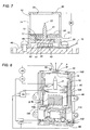
- the present invention should not be limited thereto, and is configured to use only the single emitter electrode 21 as shown in FIG. 7 .
- the tubular casing 10 is vertically divided by a partition 13 through which the emitter electrode 21 extends.
- the lower end of the casing 10 is coupled to the heat radiating plate 45, while the Peltier module 40 is accommodated between the partition 13 and the heat radiating plate 45 .
- the Peltier module 40 is configured to have a plurality of thermo-electric elements arranged between a pair of conductive circuit plate 41 and 42 , and to have the cooling side circuit plate 41 coupled to the flange 26 at the lower end of the emitter electrode 21 through a dielectric plate of good thermal conductivity.
- the flange 26 is surrounded by a heat insulation sheath 7 to reduce the heat absorption to the casing.
- the emitter electrode 21 is connected to the electrode terminal 18 on the lower side of the partition 13, while the Peltier module is connected to the connector 19 projecting outwardly from the lower end of the casing 10 .
- a water container 28 Provided on the upper side of the partition 13 is a water container 28 which absorbs an excessive amount of the water generated at the emitter electrode 21 to prevent the water from leaking to the side of the electrode terminal 18 and the Peltier module 40.
- FIG. 8 illustrates an electrostatically atomizing device in accordance with the second embodiment of the present invention which is basically identical to the above embodiment except that a fan 110 is accommodated within a single housing 100 together with the casing 10 .
- the casing 10, which carries the emitter electrode 21 , the opposed electrode 30 , the Peltier module 40, and the heat radiating fins 46 is disposed in the upper end of the housing 100, while the fan 110 is disposed in the lower end of the housing 100.
- the Peltier module is utilized as a heat exchanger defining a refrigerator at its one end, and a heat radiator at the other end.
- the fan 110 is provided to take in the ambient air through the air inlet 102 and discharge it outwardly through an air intake path 104 and a heat exchange path 106 formed in the housing 106 .
- the air intake path 104 is formed downstream of the fan 110 between the casing 10 and the housing 100 to guide the forced air flow A generated by the fan from through the air inlet 14 into the casing 10, and discharge it outwardly through the circular window 32 of the opposed electrode 30 , during which the water content of the air is condensed on the emitter electrode 21 and the mist of the charge minute particles discharged from the emitter electrode 21 is carried on the forced air flow to be expelled outwardly.
- the heat exchange path 106 is provided to guide a forced air flow B through passes around the heat radiating fins 46 on the downstream side of the fan 110 and to expel it outwardly through discharge port 108 in the wall of the housing 100.
- the air flow contacts with the heat radiating fins 46 to improve cooling effect at the Peltier module 40 .
- the heat exchange path 106 is separated from the air intake path 104 to avoid the air heated by the heat radiating fins from leaking towards the emitter electrode 21. With this result, the emitter electrode 21 is supplied with the fresh air to effectively condense the water therefrom.
- a temperature-humidity sensor 80 is provided around the air inlet 102 for detection of the environmental temperature and humidity.
- the cooling controller 50 controls the voltage applied to the Peltier module 40 to cool the emitter electrode 21 to a temperature determined by the environmental temperature and humidity, i.e., to the temperature at which a sufficient amount of water is condensed on the emitter electrode 21. Also, the cooling controller 50 is connected to a current meter 70 for monitoring a discharge current flowing between the emitter electrode 21 and the opposed electrode 30, in order to control the Peltier module for keeping the discharge current constant.
- the discharge current is proportional to the amount of the charge minute water particles discharged from the discharge end 22, or the amount of the water condensed on the emitter electrode, it is possible to continuously discharge the mist of the charged minute water particles in a constant amount by controlling the Peltier module 40 to keep the constant discharge current.
- the fan 110 is connected to an air flow controller 120 for regulating the amount of the air flow being supplied to the emitter electrode 21 and the heat radiating fins 46.
- the air flow controller 120 is connected to the current meter 70 and the temperature-humidity sensor 80 to regulate the amount of the air flow depending upon the discharge current and the environmental temperature and humidity. For example, when there is a great difference between the environmental temperature and the emitter electrode, the amount of the air flow is increased in order to enhance the cooling efficiency at the Peltier module. Also, when there is a shortage of the condensed amount of the water on the emitter electrode, the amount of air flow is increased to supply a more amount of the ambient air to the emitter electrode. On the other hand, when a sufficient amount of water is being condensed on the emitter electrode, the fan is stopped or the amount of the air flow is lowered to keep discharging the mist of the charged minute water particles in a constant amount.
- a freezing of the water condensed on the emitter electrode 21 may occur when the emitter electrode 21 is over-cooled in a particular environment.
- the cooling controller 50 controls the Peltier module 40 to raise the temperature of the emitter electrode 21 to remove the freezing.
- the cooling by the Peltier module is lowered or stopped.
- the polarity of the voltage applied to the Peltier module may be temporarily reversed to heat the emitter electrode 21.
- the cooling controller 50 can be configured to switch the functions of freezing the water content in the air and melding the frozen water in order to supply a suitable amount of water to the emitter electrode 21 .
- the emitter electrode 21 may be formed with a water container temporarily holding an excessive amount of water.
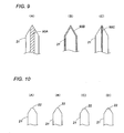
- FIG. 9(A) illustrates an example in which the emitter electrode 21 is formed in its center with the water container 90A made of a porous ceramic to exhibit a capillary action.
- FIG. 9(B) an example is illustrated in which the emitter electrode 21 is formed in its outer surface with capillary grooves extending in the axial direction to define the water container 90B .
- the water container is hydrophilically treated, while the other portion is hydrophobically finished, for example, by coating with a water-repellant layer.
- FIG. 9(A) illustrates an example in which the emitter electrode 21 is formed in its center with the water container 90A made of a porous ceramic to exhibit a capillary action.
- FIG. 9(B) an example is illustrated in which the emitter electrode 21 is formed in its outer surface with capillary grooves extending in the axial direction to define the water container 90B .
- the water container is hydrophilically treated
- the emitter electrode 21 is formed internally with a capillary gap extending in the axial direction to define the water container 90C .
- the gap man by formed in the interior of the emitter electrode by dividing the emitter electrode into two-halves or three-pieces.
- FIG. 10 illustrates various structures of giving increased water holding capacity to the discharge end 22 of at the distal end of the emitter electrode 21.
- FIG. 10(A) illustrates an example in which the discharge end 22 is formed with a flat face to hold the water thereon by the surface tension of the water.
- FIG. 10(B) illustrates an example in which a sharp projection is formed centrally on the flat face to concentrate the electric charge thereto.
- FIG. 10(C) an example is illustrated in which the discharge end is formed with a concave to hold the water therein.
- FIG. 10(D) an example is illustrated in which a sharp projection is formed centrally on the concave.
- the water supplied to the discharge end can be suitable held thereat, enabling the water to successfully induce the Rayleigh disintegration of the water and therefore assuring to give the electrostatic atomization in a stably matter. More than one projection may be formed to increase the amount of the mist.
Landscapes
- Electrostatic Spraying Apparatus (AREA)
- Organic Low-Molecular-Weight Compounds And Preparation Thereof (AREA)
- Manufacturing Of Micro-Capsules (AREA)
- Application Of Or Painting With Fluid Materials (AREA)
Claims (14)
- Dispositif de pulvérisation électrostatique comprenant :une électrode émettrice (21) ;une électrode opposée (30) opposée à ladite électrode émettrice ;un dispositif d'alimentation en eau (40, 44, 45) configuré pour procurer de l'eau sur ladite électrode émettrice (21),une source haute tension (60) configurée pour appliquer une haute tension à travers ladite électrode émettrice (21) et ladite électrode opposée (30) pour charger de manière électrostatique l'eau sur ladite électrode émettrice (21) pour pulvériser des particules d'eau infimes chargées depuis une extrémité de décharge (22) de ladite électrode émettrice (21),caractérisé en ce que
ledit dispositif d'alimentation en eau (40, 44, 45) est configuré pour refroidir ladite électrode émettrice (21) de manière à condenser l'eau sur ladite électrode émettrice (21) depuis l'air environnant. - Dispositif selon la revendication 1, dans lequel
ledit dispositif d'alimentation en eau comprend un élément de réfrigération (40) qui refroidit ladite électrode émettrice (21) pour la condensation de l'eau sur ladite électrode émettrice (21) depuis l'air environnant. - Dispositif selon la revendication 1, dans lequel
ledit dispositif d'alimentation en eau (40, 44, 45) est configuré pour avoir une fonction de congélation visant à congeler le contenu en eau de l'air environnant sur ladite électrode émettrice (21), et une fonction de mélange qui vise à mélanger l'eau congelée sur ladite électrode émettrice (21). - Dispositif selon la revendication 2, comprenant en plus
un ventilateur (110) qui est configuré pour introduire l'air environnant autour de ladite électrode émettrice (21) à travers un chemin d'admission d'air (104). - Dispositif selon la revendication 4, dans lequel
ledit élément de réfrigération (40) est combiné avec un radiateur thermique pour définir un échangeur thermique,
ledit échangeur thermique étant logé dans un boîtier (100) avec ladite électrode émettrice (21),
ledit boîtier étant formé par un chemin d'échange thermique (106) qui est séparé dudit chemin d'admission d'air pour introduire l'air environnant audit radiateur thermique et le retirer dudit boîtier. - Dispositif selon la revendication 1, dans lequel
ladite électrode émettrice (21) est formée avec un récipient d'eau (90A) qui maintient un volume de l'eau. - Dispositif selon la revendication 2, dans lequel
ledit élément de réfrigération (40) est réalisé par un module thermoélectrique à effet Peltier ayant un côté de refroidissement et un côté chauffant, ledit côté de refroidissement étant couplé à ladite électrode émettrice (21) pour la refroidir. - Dispositif selon la revendication 2, dans lequel
une pluralité desdites électrodes émettrices (21) sont disposées,
lesdites électrodes émettrices (21) étant thermiquement couplées audit élément de réfrigération (40) de manière à ce que les extrémités de décharge respectives soient refroidies à la même température,
lesdites électrodes émettrices (21) sont électriquement couplées à ladite source haute tension de manière à ce que les extrémités de décharge respectives reçoivent la même intensité de champ électrique. - Dispositif selon la revendication 8, dans lequel
la pluralité desdites électrodes émettrices (21) sont intégrées dans un ensemble d'électrodes (20) ayant une seule tige (24) couplée audit élément de réfrigération (40),
lesdites électrodes émettrices (21) s'étendant de ladite tige unique respectivement par l'intermédiaire de branches (25). - Dispositif selon la revendication 8, dans lequel
l'ensemble desdites électrodes émettrices (21) ont leurs extrémités de décharge respectives espacées par une distance identique par rapport à ladite électrode opposée (30). - Dispositif selon la revendication 8, dans lequel
ledit ensemble d'électrodes est fait du même matériau dans une structure unitaire, lesdites électrodes émettrices (21) étant disposées symétriquement autour de ladite tige (24). - Dispositif selon la revendication 11, dans lequel
ledit ensemble d'électrodes est raccordé afin de recevoir la haute tension à partir de ladite source haute tension (60) à un point de raccordement décalé desdites branches vers ledit élément de réfrigération (40). - Dispositif selon la revendication 9, dans lequel
ledit ensemble d'électrodes est doté d'une gaine d'isolation thermique couvrant une partie s'étendant desdites branches audit élément de réfrigération (40). - Dispositif selon la revendication 8, dans lequel
une pluralité desdites électrodes opposées (30) disposées respectivement en relation avec lesdites électrodes émettrices (21),
chacune desdites électrodes opposées (30) étant espacées par la même distance à chaque électrode associée parmi lesdites électrodes émettrices (21).
Applications Claiming Priority (4)
| Application Number | Priority Date | Filing Date | Title |
|---|---|---|---|
| JP2004114364A JP4625267B2 (ja) | 2004-04-08 | 2004-04-08 | 静電霧化装置 |
| JP2004182920A JP3952044B2 (ja) | 2004-06-21 | 2004-06-21 | 静電霧化装置 |
| JP2005018682A JP4442444B2 (ja) | 2005-01-26 | 2005-01-26 | 静電霧化装置 |
| PCT/JP2005/006496 WO2005097338A1 (fr) | 2004-04-08 | 2005-04-01 | Vaporisateur électrostatique |
Publications (4)
| Publication Number | Publication Date |
|---|---|
| EP1733797A1 EP1733797A1 (fr) | 2006-12-20 |
| EP1733797A4 EP1733797A4 (fr) | 2007-08-15 |
| EP1733797B1 true EP1733797B1 (fr) | 2009-01-07 |
| EP1733797B8 EP1733797B8 (fr) | 2009-04-08 |
Family
ID=35124888
Family Applications (1)
| Application Number | Title | Priority Date | Filing Date |
|---|---|---|---|
| EP05727279A Expired - Lifetime EP1733797B8 (fr) | 2004-04-08 | 2005-04-01 | Vaporisateur électrostatique |
Country Status (6)
| Country | Link |
|---|---|
| US (1) | US7874503B2 (fr) |
| EP (1) | EP1733797B8 (fr) |
| AT (1) | ATE419922T1 (fr) |
| DE (1) | DE602005012248D1 (fr) |
| TW (1) | TWI252783B (fr) |
| WO (1) | WO2005097338A1 (fr) |
Families Citing this family (47)
| Publication number | Priority date | Publication date | Assignee | Title |
|---|---|---|---|---|
| DE10260149A1 (de) | 2002-12-20 | 2004-07-01 | BSH Bosch und Siemens Hausgeräte GmbH | Vorrichtung zur Bestimmung des Leitwertes von Wäsche, Wäschetrockner und Verfahren zur Verhinderung von Schichtbildung auf Elektroden |
| ATE527907T1 (de) * | 2004-04-23 | 2011-10-15 | Panasonic Elec Works Co Ltd | Gebläseheizung mit elektrostatischem zerstäuber |
| JP4706198B2 (ja) * | 2004-07-16 | 2011-06-22 | パナソニック株式会社 | 空気浄化装置 |
| JP4645121B2 (ja) * | 2004-09-27 | 2011-03-09 | パナソニック電工株式会社 | 静電霧化装置 |
| JP4655883B2 (ja) * | 2005-07-15 | 2011-03-23 | パナソニック電工株式会社 | 静電霧化装置 |
| JP4765556B2 (ja) * | 2005-10-31 | 2011-09-07 | パナソニック電工株式会社 | 静電霧化装置 |
| US7959717B2 (en) * | 2005-12-16 | 2011-06-14 | Panasonic Electric Works Co., Ltd. | Air conditioning system with electrostatically atomizing function |
| JP4821304B2 (ja) * | 2005-12-19 | 2011-11-24 | パナソニック電工株式会社 | 静電霧化装置 |
| JP4779779B2 (ja) * | 2006-04-07 | 2011-09-28 | パナソニック電工株式会社 | 静電霧化装置 |
| JP4821437B2 (ja) * | 2006-05-26 | 2011-11-24 | パナソニック電工株式会社 | 静電霧化装置 |
| JP4552905B2 (ja) * | 2006-06-30 | 2010-09-29 | パナソニック電工株式会社 | 静電霧化装置 |
| JP4396672B2 (ja) * | 2006-08-04 | 2010-01-13 | パナソニック電工株式会社 | 車両用静電霧化装置 |
| CN102079231B (zh) * | 2006-08-09 | 2012-10-31 | 松下电器产业株式会社 | 车载用离子发生系统 |
| JP4706630B2 (ja) * | 2006-12-15 | 2011-06-22 | パナソニック電工株式会社 | 静電霧化装置 |
| JP4706632B2 (ja) * | 2006-12-22 | 2011-06-22 | パナソニック電工株式会社 | 静電霧化装置 |
| DE112008002167B4 (de) | 2007-04-26 | 2014-02-06 | Panasonic Corporation | Kühlschrank und elektrische Vorrichtung |
| EP2144023A4 (fr) * | 2007-04-26 | 2012-08-08 | Panasonic Corp | Réfrigérateur |
| JP5038800B2 (ja) * | 2007-07-09 | 2012-10-03 | カルソニックカンセイ株式会社 | 車載用空調装置 |
| BRPI0818294B1 (pt) * | 2007-10-09 | 2020-01-21 | Panasonic Corp | refrigerador e método de armazenamento no mesmo |
| NZ585074A (en) * | 2007-11-06 | 2012-06-29 | Panasonic Corp | Refrigerator with an atomization device and a protection unit to supprss current flow to the user |
| CN101849152B (zh) * | 2007-11-06 | 2013-01-23 | 松下电器产业株式会社 | 冷藏库 |
| JP2009172557A (ja) * | 2008-01-28 | 2009-08-06 | Panasonic Electric Works Co Ltd | 静電霧化装置 |
| JP2009202059A (ja) * | 2008-02-26 | 2009-09-10 | Panasonic Electric Works Co Ltd | 静電霧化装置 |
| JP5368726B2 (ja) * | 2008-04-18 | 2013-12-18 | パナソニック株式会社 | 静電霧化装置 |
| JP5324177B2 (ja) * | 2008-09-30 | 2013-10-23 | パナソニック株式会社 | 還元水ミスト発生装置、還元水ミスト発生方法 |
| EP2233212A1 (fr) * | 2009-03-26 | 2010-09-29 | Panasonic Electric Works Co., Ltd | Dispositif d'atomisation électrostatique |
| AU2010229384A1 (en) * | 2009-03-26 | 2011-10-27 | Panasonic Corporation | Electrostatic atomizing apparatus and method for manufacturing same |
| JP2011025204A (ja) * | 2009-07-28 | 2011-02-10 | Panasonic Electric Works Co Ltd | 静電霧化装置 |
| JP5227281B2 (ja) * | 2009-09-25 | 2013-07-03 | パナソニック株式会社 | 静電霧化装置 |
| KR101294874B1 (ko) * | 2010-01-25 | 2013-08-08 | 가부시끼가이샤 도시바 | 정전 분무화 장치 및 전기 청소기 |
| US20110232312A1 (en) * | 2010-03-24 | 2011-09-29 | Whirlpool Corporation | Flexible wick as water delivery system |
| US9004369B2 (en) * | 2010-03-24 | 2015-04-14 | Whirlpool Corporation | Systems and methods for multi-sense control algorithm for atomizers in refrigerators |
| USD681571S1 (en) * | 2010-09-29 | 2013-05-07 | Panasonic Corporation | Electrode |
| USD681572S1 (en) * | 2010-09-29 | 2013-05-07 | Panasonic Corporation | Electrode |
| USD682226S1 (en) * | 2010-09-29 | 2013-05-14 | Panasonic Corporation | Electrostatic atomized water particle generating module |
| JP2011073003A (ja) * | 2011-01-17 | 2011-04-14 | Panasonic Electric Works Co Ltd | 静電霧化装置 |
| JP1434986S (fr) * | 2011-04-21 | 2015-02-23 | ||
| JP1434985S (fr) * | 2011-04-21 | 2015-02-23 | ||
| JP5762872B2 (ja) | 2011-07-29 | 2015-08-12 | 住友化学株式会社 | 静電噴霧装置 |
| US20130140385A1 (en) * | 2011-08-17 | 2013-06-06 | Busek Co., Inc. | Charge injected fluid assist liquid atomizer |
| CN104998290A (zh) * | 2015-07-07 | 2015-10-28 | 安徽桑乐金股份有限公司 | 一种浮力超声雾化结构及具有该结构的盐雾发生器 |
| CN206810524U (zh) * | 2017-05-31 | 2017-12-29 | 北京小米移动软件有限公司 | 一种水微粒发生装置 |
| CN108970823B (zh) * | 2017-05-31 | 2021-08-06 | 北京小米移动软件有限公司 | 一种水微粒发生装置 |
| JP1633395S (fr) * | 2018-07-31 | 2019-06-10 | ||
| USD932451S1 (en) * | 2019-09-20 | 2021-10-05 | Panasonic Intellectual Property Management Co., Ltd. | Discharge device |
| CN111146694B (zh) * | 2020-01-19 | 2025-04-04 | 杭州大湛机电科技有限公司 | 一种可更换式纳米水离子发生器 |
| CN113300222B (zh) * | 2021-06-30 | 2022-05-17 | 杭州大湛机电科技有限公司 | 一种纳米水离子群发生器 |
Family Cites Families (20)
| Publication number | Priority date | Publication date | Assignee | Title |
|---|---|---|---|---|
| JPS62144774A (ja) * | 1985-12-19 | 1987-06-27 | Agency Of Ind Science & Technol | 液体の微粒化方法 |
| ATE199328T1 (de) | 1990-11-12 | 2001-03-15 | Procter & Gamble | Sprühvorrichtung |
| JPH04205872A (ja) | 1990-11-30 | 1992-07-28 | Hitachi Ltd | 磁気記録再生装置 |
| JP3533826B2 (ja) * | 1996-05-29 | 2004-05-31 | アイシン精機株式会社 | 熱変換装置 |
| JPH119671A (ja) | 1997-06-23 | 1999-01-19 | Sharp Corp | 複合消臭フィルタ及びそれを備える複合消臭フィルタ装置 |
| JPH1156994A (ja) | 1997-08-28 | 1999-03-02 | Takahashi Works:Kk | バッテリ駆動による脱臭装置 |
| JP2001286546A (ja) | 2000-04-07 | 2001-10-16 | Ricoh Elemex Corp | 消臭剤噴霧装置 |
| JP2002203657A (ja) * | 2000-12-27 | 2002-07-19 | Daikin Ind Ltd | イオン発生器 |
| JP2002263026A (ja) | 2001-03-09 | 2002-09-17 | Com Institute:Kk | シャワーヘッド及び化粧料組成物 |
| JP3920050B2 (ja) * | 2001-06-27 | 2007-05-30 | シャープ株式会社 | 加湿装置 |
| JP5149473B2 (ja) | 2001-09-14 | 2013-02-20 | パナソニック株式会社 | 脱臭装置 |
| MXPA04008203A (es) * | 2002-02-25 | 2004-11-26 | Procter & Gamble | Dispositivo electrostatico de rociado. |
| JP2003287316A (ja) | 2002-03-28 | 2003-10-10 | Matsushita Refrig Co Ltd | 水分供給装置 |
| EP2428278A3 (fr) * | 2003-05-27 | 2012-04-25 | Panasonic Electric Works Co., Ltd | Eau chargée en fines particules et procédé pour créer un environnement dans lequel est dispersé un brouillard d'eau chargée en fines particules |
| JP4232542B2 (ja) * | 2003-06-04 | 2009-03-04 | パナソニック電工株式会社 | 静電霧化装置及びこれを備えた加湿装置 |
| JP4016934B2 (ja) | 2003-10-30 | 2007-12-05 | 松下電工株式会社 | 静電霧化装置 |
| JP4400210B2 (ja) * | 2003-12-22 | 2010-01-20 | パナソニック電工株式会社 | 静電霧化装置 |
| EP1733798B8 (fr) * | 2004-04-08 | 2012-02-15 | Panasonic Electric Works Co., Ltd. | Atomiseur électrostatique |
| DE202005012863U1 (de) * | 2005-08-12 | 2005-10-27 | J. Wagner Ag | Elektrodenhalter für eine Pulversprühvorrichtung |
| US7718029B2 (en) * | 2006-08-01 | 2010-05-18 | Applied Materials, Inc. | Self-passivating plasma resistant material for joining chamber components |
-
2005
- 2005-04-01 WO PCT/JP2005/006496 patent/WO2005097338A1/fr not_active Ceased
- 2005-04-01 EP EP05727279A patent/EP1733797B8/fr not_active Expired - Lifetime
- 2005-04-01 DE DE602005012248T patent/DE602005012248D1/de not_active Expired - Lifetime
- 2005-04-01 US US11/547,132 patent/US7874503B2/en active Active
- 2005-04-01 AT AT05727279T patent/ATE419922T1/de not_active IP Right Cessation
- 2005-04-08 TW TW094111259A patent/TWI252783B/zh not_active IP Right Cessation
Also Published As
| Publication number | Publication date |
|---|---|
| EP1733797A4 (fr) | 2007-08-15 |
| HK1103048A1 (zh) | 2007-12-14 |
| US20090001200A1 (en) | 2009-01-01 |
| TWI252783B (en) | 2006-04-11 |
| TW200533421A (en) | 2005-10-16 |
| ATE419922T1 (de) | 2009-01-15 |
| US7874503B2 (en) | 2011-01-25 |
| WO2005097338A1 (fr) | 2005-10-20 |
| DE602005012248D1 (de) | 2009-02-26 |
| EP1733797A1 (fr) | 2006-12-20 |
| EP1733797B8 (fr) | 2009-04-08 |
Similar Documents
| Publication | Publication Date | Title |
|---|---|---|
| EP1733797B1 (fr) | Vaporisateur électrostatique | |
| JP4625267B2 (ja) | 静電霧化装置 | |
| EP1738667B1 (fr) | Radiateur soufflant equipe d'un pulverisateur electrostatique | |
| EP0614055B1 (fr) | Dispositif pour l'humidification et l'ionisation d'air | |
| EP1745716B1 (fr) | Atomiseur électrostatique | |
| TWI353889B (en) | Electrostatic atomizer and hot air blower having t | |
| EP2390007B1 (fr) | Atomiseur électrostatique | |
| WO2005042171A1 (fr) | Atomiseur electrostatique | |
| KR20060087462A (ko) | 정전 분무 장치를 구비하는 헤어드라이어 | |
| JP2009131407A (ja) | ドライヤー | |
| CN101147634B (zh) | 离子干发器 | |
| CN102105081A (zh) | 护发装置 | |
| WO2006129592A1 (fr) | Pulvérisateur électrostatique et soufflante l’utilisant | |
| CN102068103B (zh) | 头发护理装置 | |
| JPH0311636Y2 (fr) | ||
| JP4442444B2 (ja) | 静電霧化装置 | |
| Tepper et al. | A study of ionization and collection efficiencies in electrospray-based electrostatic precipitators | |
| CN114379333B (zh) | 一种车辆内部空气净化用活性雾离子发生装置 | |
| JP2003106578A (ja) | 加湿装置及びこれを備えた電気暖房機器 | |
| JP2023021041A (ja) | アトマイザー及び電子霧化装置 | |
| JP4788835B2 (ja) | イオンミストによる髪の保湿方法及び髪の保湿装置 | |
| WO2007072776A1 (fr) | Atomiseur electrostatique | |
| JP5323544B2 (ja) | 静電霧化装置を備えたヘアドライヤー | |
| HK1103048B (en) | Electrostatically atomizing device | |
| JP2019000824A (ja) | 帯電粒子発生装置、および、ヘアケア装置 |
Legal Events
| Date | Code | Title | Description |
|---|---|---|---|
| PUAI | Public reference made under article 153(3) epc to a published international application that has entered the european phase |
Free format text: ORIGINAL CODE: 0009012 |
|
| 17P | Request for examination filed |
Effective date: 20060920 |
|
| AK | Designated contracting states |
Kind code of ref document: A1 Designated state(s): AT BE BG CH CY CZ DE DK EE ES FI FR GB GR HU IE IS IT LI LT LU MC NL PL PT RO SE SI SK TR |
|
| DAX | Request for extension of the european patent (deleted) | ||
| A4 | Supplementary search report drawn up and despatched |
Effective date: 20070717 |
|
| 17Q | First examination report despatched |
Effective date: 20071011 |
|
| GRAP | Despatch of communication of intention to grant a patent |
Free format text: ORIGINAL CODE: EPIDOSNIGR1 |
|
| GRAS | Grant fee paid |
Free format text: ORIGINAL CODE: EPIDOSNIGR3 |
|
| GRAA | (expected) grant |
Free format text: ORIGINAL CODE: 0009210 |
|
| AK | Designated contracting states |
Kind code of ref document: B1 Designated state(s): AT BE BG CH CY CZ DE DK EE ES FI FR GB GR HU IE IS IT LI LT LU MC NL PL PT RO SE SI SK TR |
|
| REG | Reference to a national code |
Ref country code: GB Ref legal event code: FG4D |
|
| REG | Reference to a national code |
Ref country code: CH Ref legal event code: EP |
|
| RAP2 | Party data changed (patent owner data changed or rights of a patent transferred) |
Owner name: PANASONIC ELECTRIC WORKS CO., LTD. |
|
| REG | Reference to a national code |
Ref country code: IE Ref legal event code: FG4D |
|
| REF | Corresponds to: |
Ref document number: 602005012248 Country of ref document: DE Date of ref document: 20090226 Kind code of ref document: P |
|
| NLT2 | Nl: modifications (of names), taken from the european patent patent bulletin |
Owner name: PANASONIC ELECTRIC WORKS CO., LTD. Effective date: 20090218 |
|
| PG25 | Lapsed in a contracting state [announced via postgrant information from national office to epo] |
Ref country code: SI Free format text: LAPSE BECAUSE OF FAILURE TO SUBMIT A TRANSLATION OF THE DESCRIPTION OR TO PAY THE FEE WITHIN THE PRESCRIBED TIME-LIMIT Effective date: 20090107 Ref country code: NL Free format text: LAPSE BECAUSE OF FAILURE TO SUBMIT A TRANSLATION OF THE DESCRIPTION OR TO PAY THE FEE WITHIN THE PRESCRIBED TIME-LIMIT Effective date: 20090107 |
|
| NLV1 | Nl: lapsed or annulled due to failure to fulfill the requirements of art. 29p and 29m of the patents act | ||
| PG25 | Lapsed in a contracting state [announced via postgrant information from national office to epo] |
Ref country code: ES Free format text: LAPSE BECAUSE OF FAILURE TO SUBMIT A TRANSLATION OF THE DESCRIPTION OR TO PAY THE FEE WITHIN THE PRESCRIBED TIME-LIMIT Effective date: 20090418 Ref country code: FI Free format text: LAPSE BECAUSE OF FAILURE TO SUBMIT A TRANSLATION OF THE DESCRIPTION OR TO PAY THE FEE WITHIN THE PRESCRIBED TIME-LIMIT Effective date: 20090107 Ref country code: LT Free format text: LAPSE BECAUSE OF FAILURE TO SUBMIT A TRANSLATION OF THE DESCRIPTION OR TO PAY THE FEE WITHIN THE PRESCRIBED TIME-LIMIT Effective date: 20090107 |
|
| PG25 | Lapsed in a contracting state [announced via postgrant information from national office to epo] |
Ref country code: IS Free format text: LAPSE BECAUSE OF FAILURE TO SUBMIT A TRANSLATION OF THE DESCRIPTION OR TO PAY THE FEE WITHIN THE PRESCRIBED TIME-LIMIT Effective date: 20090507 Ref country code: PT Free format text: LAPSE BECAUSE OF FAILURE TO SUBMIT A TRANSLATION OF THE DESCRIPTION OR TO PAY THE FEE WITHIN THE PRESCRIBED TIME-LIMIT Effective date: 20090608 Ref country code: PL Free format text: LAPSE BECAUSE OF FAILURE TO SUBMIT A TRANSLATION OF THE DESCRIPTION OR TO PAY THE FEE WITHIN THE PRESCRIBED TIME-LIMIT Effective date: 20090107 Ref country code: AT Free format text: LAPSE BECAUSE OF FAILURE TO SUBMIT A TRANSLATION OF THE DESCRIPTION OR TO PAY THE FEE WITHIN THE PRESCRIBED TIME-LIMIT Effective date: 20090107 Ref country code: SE Free format text: LAPSE BECAUSE OF FAILURE TO SUBMIT A TRANSLATION OF THE DESCRIPTION OR TO PAY THE FEE WITHIN THE PRESCRIBED TIME-LIMIT Effective date: 20090407 |
|
| PG25 | Lapsed in a contracting state [announced via postgrant information from national office to epo] |
Ref country code: BE Free format text: LAPSE BECAUSE OF FAILURE TO SUBMIT A TRANSLATION OF THE DESCRIPTION OR TO PAY THE FEE WITHIN THE PRESCRIBED TIME-LIMIT Effective date: 20090107 |
|
| PG25 | Lapsed in a contracting state [announced via postgrant information from national office to epo] |
Ref country code: EE Free format text: LAPSE BECAUSE OF FAILURE TO SUBMIT A TRANSLATION OF THE DESCRIPTION OR TO PAY THE FEE WITHIN THE PRESCRIBED TIME-LIMIT Effective date: 20090107 Ref country code: DK Free format text: LAPSE BECAUSE OF FAILURE TO SUBMIT A TRANSLATION OF THE DESCRIPTION OR TO PAY THE FEE WITHIN THE PRESCRIBED TIME-LIMIT Effective date: 20090107 Ref country code: CZ Free format text: LAPSE BECAUSE OF FAILURE TO SUBMIT A TRANSLATION OF THE DESCRIPTION OR TO PAY THE FEE WITHIN THE PRESCRIBED TIME-LIMIT Effective date: 20090107 |
|
| PLBE | No opposition filed within time limit |
Free format text: ORIGINAL CODE: 0009261 |
|
| STAA | Information on the status of an ep patent application or granted ep patent |
Free format text: STATUS: NO OPPOSITION FILED WITHIN TIME LIMIT |
|
| PG25 | Lapsed in a contracting state [announced via postgrant information from national office to epo] |
Ref country code: SK Free format text: LAPSE BECAUSE OF FAILURE TO SUBMIT A TRANSLATION OF THE DESCRIPTION OR TO PAY THE FEE WITHIN THE PRESCRIBED TIME-LIMIT Effective date: 20090107 Ref country code: RO Free format text: LAPSE BECAUSE OF FAILURE TO SUBMIT A TRANSLATION OF THE DESCRIPTION OR TO PAY THE FEE WITHIN THE PRESCRIBED TIME-LIMIT Effective date: 20090107 |
|
| REG | Reference to a national code |
Ref country code: CH Ref legal event code: PL |
|
| 26N | No opposition filed |
Effective date: 20091008 |
|
| PG25 | Lapsed in a contracting state [announced via postgrant information from national office to epo] |
Ref country code: BG Free format text: LAPSE BECAUSE OF FAILURE TO SUBMIT A TRANSLATION OF THE DESCRIPTION OR TO PAY THE FEE WITHIN THE PRESCRIBED TIME-LIMIT Effective date: 20090407 Ref country code: CH Free format text: LAPSE BECAUSE OF NON-PAYMENT OF DUE FEES Effective date: 20090430 Ref country code: LI Free format text: LAPSE BECAUSE OF NON-PAYMENT OF DUE FEES Effective date: 20090430 |
|
| PG25 | Lapsed in a contracting state [announced via postgrant information from national office to epo] |
Ref country code: IE Free format text: LAPSE BECAUSE OF NON-PAYMENT OF DUE FEES Effective date: 20090401 Ref country code: MC Free format text: LAPSE BECAUSE OF NON-PAYMENT OF DUE FEES Effective date: 20090430 |
|
| PG25 | Lapsed in a contracting state [announced via postgrant information from national office to epo] |
Ref country code: GR Free format text: LAPSE BECAUSE OF FAILURE TO SUBMIT A TRANSLATION OF THE DESCRIPTION OR TO PAY THE FEE WITHIN THE PRESCRIBED TIME-LIMIT Effective date: 20090408 |
|
| PG25 | Lapsed in a contracting state [announced via postgrant information from national office to epo] |
Ref country code: LU Free format text: LAPSE BECAUSE OF NON-PAYMENT OF DUE FEES Effective date: 20090401 |
|
| PG25 | Lapsed in a contracting state [announced via postgrant information from national office to epo] |
Ref country code: HU Free format text: LAPSE BECAUSE OF FAILURE TO SUBMIT A TRANSLATION OF THE DESCRIPTION OR TO PAY THE FEE WITHIN THE PRESCRIBED TIME-LIMIT Effective date: 20090708 |
|
| PG25 | Lapsed in a contracting state [announced via postgrant information from national office to epo] |
Ref country code: TR Free format text: LAPSE BECAUSE OF FAILURE TO SUBMIT A TRANSLATION OF THE DESCRIPTION OR TO PAY THE FEE WITHIN THE PRESCRIBED TIME-LIMIT Effective date: 20090107 |
|
| PG25 | Lapsed in a contracting state [announced via postgrant information from national office to epo] |
Ref country code: CY Free format text: LAPSE BECAUSE OF FAILURE TO SUBMIT A TRANSLATION OF THE DESCRIPTION OR TO PAY THE FEE WITHIN THE PRESCRIBED TIME-LIMIT Effective date: 20090107 |
|
| PGFP | Annual fee paid to national office [announced via postgrant information from national office to epo] |
Ref country code: GB Payment date: 20130327 Year of fee payment: 9 |
|
| PGFP | Annual fee paid to national office [announced via postgrant information from national office to epo] |
Ref country code: FR Payment date: 20130625 Year of fee payment: 9 |
|
| GBPC | Gb: european patent ceased through non-payment of renewal fee |
Effective date: 20140401 |
|
| REG | Reference to a national code |
Ref country code: FR Ref legal event code: ST Effective date: 20141231 |
|
| PG25 | Lapsed in a contracting state [announced via postgrant information from national office to epo] |
Ref country code: GB Free format text: LAPSE BECAUSE OF NON-PAYMENT OF DUE FEES Effective date: 20140401 |
|
| PG25 | Lapsed in a contracting state [announced via postgrant information from national office to epo] |
Ref country code: FR Free format text: LAPSE BECAUSE OF NON-PAYMENT OF DUE FEES Effective date: 20140430 |
|
| PGFP | Annual fee paid to national office [announced via postgrant information from national office to epo] |
Ref country code: IT Payment date: 20240313 Year of fee payment: 20 |
|
| PGFP | Annual fee paid to national office [announced via postgrant information from national office to epo] |
Ref country code: DE Payment date: 20240206 Year of fee payment: 20 |
|
| REG | Reference to a national code |
Ref country code: DE Ref legal event code: R071 Ref document number: 602005012248 Country of ref document: DE |