EP1733862A1 - Unité de fermeture d'une presse à injecter et procédé de réglage de la longueur effective de colonne - Google Patents
Unité de fermeture d'une presse à injecter et procédé de réglage de la longueur effective de colonne Download PDFInfo
- Publication number
- EP1733862A1 EP1733862A1 EP05018922A EP05018922A EP1733862A1 EP 1733862 A1 EP1733862 A1 EP 1733862A1 EP 05018922 A EP05018922 A EP 05018922A EP 05018922 A EP05018922 A EP 05018922A EP 1733862 A1 EP1733862 A1 EP 1733862A1
- Authority
- EP
- European Patent Office
- Prior art keywords
- mold clamping
- tie bar
- tie bars
- mold
- tie
- Prior art date
- Legal status (The legal status is an assumption and is not a legal conclusion. Google has not performed a legal analysis and makes no representation as to the accuracy of the status listed.)
- Granted
Links
Images


Classifications
-
- B—PERFORMING OPERATIONS; TRANSPORTING
- B29—WORKING OF PLASTICS; WORKING OF SUBSTANCES IN A PLASTIC STATE IN GENERAL
- B29C—SHAPING OR JOINING OF PLASTICS; SHAPING OF MATERIAL IN A PLASTIC STATE, NOT OTHERWISE PROVIDED FOR; AFTER-TREATMENT OF THE SHAPED PRODUCTS, e.g. REPAIRING
- B29C45/00—Injection moulding, i.e. forcing the required volume of moulding material through a nozzle into a closed mould; Apparatus therefor
- B29C45/17—Component parts, details or accessories; Auxiliary operations
- B29C45/1751—Adjustment means allowing the use of moulds of different thicknesses
-
- B—PERFORMING OPERATIONS; TRANSPORTING
- B29—WORKING OF PLASTICS; WORKING OF SUBSTANCES IN A PLASTIC STATE IN GENERAL
- B29C—SHAPING OR JOINING OF PLASTICS; SHAPING OF MATERIAL IN A PLASTIC STATE, NOT OTHERWISE PROVIDED FOR; AFTER-TREATMENT OF THE SHAPED PRODUCTS, e.g. REPAIRING
- B29C45/00—Injection moulding, i.e. forcing the required volume of moulding material through a nozzle into a closed mould; Apparatus therefor
- B29C45/17—Component parts, details or accessories; Auxiliary operations
- B29C45/76—Measuring, controlling or regulating
- B29C45/7653—Measuring, controlling or regulating mould clamping forces
Definitions
- the present invention relates to a mold clamping apparatus of an injection molding machine and to a method of adjusting effective lengths of tie bars.
- FIG. 6 is a view schematically showing a related molding clamping apparatus, in which FIG. 6A is a front view thereof, and FIG. 6B is a sectional view taken along a line XI-XI of FIG. 6A.
- the mold clamping apparatus 101 shown in FIG. 6 includes a fixed platen 106 to which a fixed-side mold 106a is attached, a movable platen 107 to which a moving-side mold 107a is attached and which is capable of moving with respect to the fixed platen 106, and a mold clamping housing 108 which is connected to the movable platen 107 through a toggle link type or direct hydraulic pressing mechanism 111.
- Four tie bars 102A to 102D are provided between the fixed platen 106 and the mold clamping housing 108, and the movable platen 107 can move along the tie bars.
- each of the tie bars 102A to 102D Male screws are formed at both end portions of each of the tie bars 102A to 102D, tie bar nuts 110 are screwed to the male screws at the side of the fixed platen 106, and female screws formed in mold thickness adjusting units 109 are screwed to the male screws at the side of the mold clamping housing 108.
- the effective length of each of the tie bars can be adjusted by varying the distance between the tie bar nuts 110 and the mold thickness adjusting units 109.
- a first method of varying the distance between the tie bar nuts 110 and the mold thickness adjusting units 109 by providing die height adjusting nuts to the mold thickness adjusting units 109 and by rotating the die height adjusting nuts has been known.
- a second method of varying the distance between the tie bar nuts 110 and the mold thickness adjusting units 109 by forming the male screws formed at both end portions of each of the tie bars as screws inversed to each other or by forming pitches thereof different to each other, and by rotating only the tie bars in a state in which the tie bar nuts 110 and the mold thickness adjusting units 109 are fixed has been known.
- the first method is disclosed in Japanese Patent No. 3549280 .
- the balance of the extended amount of the four tie bars 102A to 102D when the mold clamping force is generated by operating the mold clamping apparatus 101, and furthermore the balance of the mold clamping force acting on the molds can be adjusted by adjusting individually the effective length of each of the tie bars by the above-described methods.
- the first method has following problems.
- the second method has following problems.
- a mold clamping apparatus of an injection molding machine comprises a fixed platen to which a fixed-side mold is attached, a mold clamping housing, at least one of tie bar provided between the fixed platen and the mold clamping housing, a movable platen to which a moving-side mold is attached and which is capable of moving with respect to the fixed platen along the tie bar, a heater for heating the tie bar, a sensor for sensing a temperature of a portion heated by the heater, the heater and the sensor being provided to each tie bar, and a temperature adjustor which is connected to the heater and the sensor and controls the temperature of the heated portion of the tie bar.
- the tie bar is heated by the heater.
- the tie bar heated by the heater is adjacent to thin portions of a molded product injected in the mold.
- the effective lengths of the tie bars themselves are varied due to the thermal expansion depending on the heated temperature.
- the effective length of each of the tie bars is adjusted individually such that the balance of the extended amount of each of the tie bars when the mold clamping force is generated by closing the mold, and furthermore the balance of the mold clamping force acting on the molds can be adjusted.
- the invention it is possible to adjust the effective lengths of the tie bars by a simple and inexpensive construction of the heaters, the sensors, and the temperature adjustor. Furthermore, it is possible to perform the adjustment of the effective lengths of the tie bars without disassembling the mold clamping apparatus, and furthermore it is possible to perform the adjustment during the time of the molding operation. Accordingly, according to the invention, it is possible to perform the adjustment of the effective lengths of the tie bars in a short time.
- FIG. 1 is a view schematically showing a mold clamping apparatus according to an embodiment of the invention, in which FIG. 1A is a front view thereof and FIG. 1B is a sectional view taken along a line I-I of FIG. 1A.
- the mold clamping apparatus 1 includes a fixed platen 6 to which a fixed-side mold 6a is attached, a movable platen 7 to which a moving-side mold 7a is attached and which is capable of moving with respect to the fixed platen 6, and a mold clamping housing 8 which is connected to the movable platen 7 through a toggle link type or direct hydraulic pressing mechanism 11, like the mold clamping apparatus 101 shown in FIG. 6.
- Four tie bars 2A to 2D are provided between the fixed platen 6 and the mold clamping housing 8, and the movable platen 7 can move along the tie bars.
- tie bar nuts 10 are screwed to the male screws at the side of the fixed platen 6, and female screws formed in mold thickness adjusting units 9 are screwed to the male screws at the side of the mold clamping housing 8.
- four tie bars 2A to 2D are provided with heaters 3A to 3D for heating predetermined regions of each of the tie bars, and sensors 4A to 4D for sensing the temperatures of regions heated by the heaters 3A to 3D, respectively.
- the heaters 3A to 3D and sensors 4A to 4D are connected to a temperature adjustor 5, which controls the temperatures of the heated regions of the tie bars. According to the above-described construction, it is possible to adjust individually temperature of the heated region of each of the tie bars. As a result, the effective lengths of the tie bars 2A to 2D themselves are varied due to the thermal expansion depending on the temperature of the heated regions.
- the effective length of each of the tie bars is adjusted individually such that the balance of the extended amount of each of the tie bars 2A to 2D when the mold clamping force is generated by closing the mold, and furthermore the balance of the mold clamping force acting on the molds 6a and 7a can be adjusted.
- the mold clamping apparatus 1 of the present embodiment it is possible to adjust the effective lengths of the tie bars 2A to 2D by a simple and inexpensive construction which includes the heaters 3A to 3D, the sensors 4A to 4D, and the temperature adjustor 5. Further, it is possible to perform the adjustment of the effective lengths of the tie bars 2A to 2D without disassembling the mold clamping apparatus 1, and furthermore it is possible to perform the adjustment during the time of the molding operation. Therefore, according to the present embodiment, it is possible to perform the adjustment of the effective lengths of the tie bars in a short time.
- the effective length adjustment is needed in case that it is desired to reduce the variance of substrate thickness generated when the molds are mounted and the DVD is molded actually, after the test working of the injection molding machine in the factory is finished and is supplied to a user.
- the substrate thickness of the DVD molded in the molds 6a and 7a is small at the side of the tie bar 2A, when the molds 6a and 7a are seen from I-I direction of FIG. 1A.
- the extended amount of the tie bar 2A at the time of the generation of the mold clamping force is made small, such that the clamping force of the molds 6a and 7a at the portion adjacent to the tie bar 2A is made small, whereby the substrate thickness of the molded product is made large. Therefore, the above-described problem can be removed.
- ⁇ means a coefficient of linear expansion
- H means a length of the tie bar of which temperature is controlled by the heater
- T means an initially set temperature of the heater
- ⁇ T means a variation of the set temperature of the heater
- ⁇ L means an extended amount of the tie bar at the time of the generation of the mold clamping force at the initially set temperature.
- the length H of the thermally adjusted tie bar is 120 mm
- the extended amount ⁇ L of the tie bar at the time of the generation of the mold clamping force at the initially set temperature is 0.3 mm (corresponding to 10t)
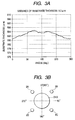
- FIG. 2 shows the theoretical value and measured value in case that the initially set temperature of the four tie bars 2A to 2D is 40°C and the temperature of only the tie bar 2A is raised.
- the theoretical value and the measured value are well coincided with each other, and it can be understood that the mold clamping force can be controlled by the temperature control.
Landscapes
- Engineering & Computer Science (AREA)
- Manufacturing & Machinery (AREA)
- Mechanical Engineering (AREA)
- Moulds For Moulding Plastics Or The Like (AREA)
- Injection Moulding Of Plastics Or The Like (AREA)
Applications Claiming Priority (1)
| Application Number | Priority Date | Filing Date | Title |
|---|---|---|---|
| JP2005178146A JP2006347078A (ja) | 2005-06-17 | 2005-06-17 | 射出成形機の型締装置およびタイバー有効長調節方法 |
Publications (2)
| Publication Number | Publication Date |
|---|---|
| EP1733862A1 true EP1733862A1 (fr) | 2006-12-20 |
| EP1733862B1 EP1733862B1 (fr) | 2013-11-27 |
Family
ID=37054740
Family Applications (1)
| Application Number | Title | Priority Date | Filing Date |
|---|---|---|---|
| EP05018922.4A Expired - Lifetime EP1733862B1 (fr) | 2005-06-17 | 2005-08-31 | Procédé de réglage de la longueur effective des colonnes d'une unité de fermeture d'une presse à injecter |
Country Status (5)
| Country | Link |
|---|---|
| US (1) | US7458796B2 (fr) |
| EP (1) | EP1733862B1 (fr) |
| JP (1) | JP2006347078A (fr) |
| CN (1) | CN1880045B (fr) |
| TW (1) | TWI267437B (fr) |
Cited By (1)
| Publication number | Priority date | Publication date | Assignee | Title |
|---|---|---|---|---|
| CN104416875A (zh) * | 2013-08-29 | 2015-03-18 | 发那科株式会社 | 具备模盘中心位置调整功能的注塑成型机的合模装置 |
Families Citing this family (10)
| Publication number | Priority date | Publication date | Assignee | Title |
|---|---|---|---|---|
| JP2009154454A (ja) * | 2007-12-27 | 2009-07-16 | Japan Steel Works Ltd:The | 射出成形機の型締装置 |
| JP5602887B2 (ja) * | 2013-01-09 | 2014-10-08 | ファナック株式会社 | 射出成形機の型締装置 |
| JP2014162060A (ja) | 2013-02-22 | 2014-09-08 | Fanuc Ltd | 射出成形機の型締装置 |
| JP5770317B2 (ja) * | 2014-01-15 | 2015-08-26 | ファナック株式会社 | 射出成形機の型締力設定装置および型締力設定方法 |
| JP6644473B2 (ja) * | 2015-03-27 | 2020-02-12 | 住友重機械工業株式会社 | 射出成形機 |
| JP6517063B2 (ja) * | 2015-03-27 | 2019-05-22 | 住友重機械工業株式会社 | 射出成形機 |
| JP6587819B2 (ja) * | 2015-03-27 | 2019-10-09 | 住友重機械工業株式会社 | 射出成形機 |
| JP6591303B2 (ja) * | 2016-01-29 | 2019-10-16 | 住友重機械工業株式会社 | 射出成形機 |
| JP7175674B2 (ja) * | 2018-08-27 | 2022-11-21 | 住友重機械工業株式会社 | 射出成形機 |
| US11224996B2 (en) * | 2019-03-01 | 2022-01-18 | The Boeing Company | Mold assembly |
Citations (6)
| Publication number | Priority date | Publication date | Assignee | Title |
|---|---|---|---|---|
| US4345890A (en) * | 1979-06-11 | 1982-08-24 | Netstal-Maschinen Ag | Injection molding machine having mold locking unit equipped with toggle drive and hydraulic locking mechanism |
| JPH0275499A (ja) | 1988-09-08 | 1990-03-15 | Yotaro Hatamura | ダイハイト調整方法 |
| JPH0338320A (ja) * | 1989-07-05 | 1991-02-19 | Nissei Plastics Ind Co | 射出圧縮成形機 |
| JPH0338320B2 (fr) | 1982-01-14 | 1991-06-10 | Hasegawa T Co Ltd | |
| WO2002062554A1 (fr) | 2001-02-06 | 2002-08-15 | O.T.B. Group B.V. | Procede et installation pour le moulage par injection d'un article en plastique |
| JP2005178146A (ja) | 2003-12-18 | 2005-07-07 | Calp Corp | 自動車用部品の成形方法 |
Family Cites Families (10)
| Publication number | Priority date | Publication date | Assignee | Title |
|---|---|---|---|---|
| US4685876A (en) * | 1986-03-24 | 1987-08-11 | Cincinnati Milacron Inc. | Toggle injection molding clamping force monitor |
| SE462379B (sv) * | 1987-08-07 | 1990-06-18 | Bo Nilsson | Foerfarande foer styrning av vissa parametrar vid framstaellning av plastvaror |
| US4869659A (en) * | 1987-09-29 | 1989-09-26 | Sumitomo Heavy Industries, Ltd. | Toggle-type die-fastening apparatus |
| JP2678929B2 (ja) * | 1988-11-30 | 1997-11-19 | 東芝機械株式会社 | 成形機の型締装置 |
| US5161594A (en) * | 1988-12-21 | 1992-11-10 | Raymond Engineering Inc. | Tie bar monitoring system |
| JPH0326515A (ja) | 1989-06-26 | 1991-02-05 | Toshiba Corp | 樹脂成形装置の金型保護装置 |
| US5059365A (en) * | 1990-05-17 | 1991-10-22 | Cincinnati Milacron Inc. | Method of setting and maintaining a desired mold clamping force |
| JP3549280B2 (ja) | 1995-03-23 | 2004-08-04 | ファナック株式会社 | 射出成形機の型締力バランス調整方法 |
| JPH11240053A (ja) | 1998-02-25 | 1999-09-07 | Sumitomo Heavy Ind Ltd | 型締装置 |
| JP2005029495A (ja) | 2003-07-10 | 2005-02-03 | Toray Ind Inc | フェノール類の吸着分離法 |
-
2005
- 2005-06-17 JP JP2005178146A patent/JP2006347078A/ja active Pending
- 2005-08-30 TW TW094129598A patent/TWI267437B/zh not_active IP Right Cessation
- 2005-08-31 CN CN200510097665XA patent/CN1880045B/zh not_active Expired - Lifetime
- 2005-08-31 EP EP05018922.4A patent/EP1733862B1/fr not_active Expired - Lifetime
-
2006
- 2006-05-22 US US11/437,816 patent/US7458796B2/en active Active
Patent Citations (6)
| Publication number | Priority date | Publication date | Assignee | Title |
|---|---|---|---|---|
| US4345890A (en) * | 1979-06-11 | 1982-08-24 | Netstal-Maschinen Ag | Injection molding machine having mold locking unit equipped with toggle drive and hydraulic locking mechanism |
| JPH0338320B2 (fr) | 1982-01-14 | 1991-06-10 | Hasegawa T Co Ltd | |
| JPH0275499A (ja) | 1988-09-08 | 1990-03-15 | Yotaro Hatamura | ダイハイト調整方法 |
| JPH0338320A (ja) * | 1989-07-05 | 1991-02-19 | Nissei Plastics Ind Co | 射出圧縮成形機 |
| WO2002062554A1 (fr) | 2001-02-06 | 2002-08-15 | O.T.B. Group B.V. | Procede et installation pour le moulage par injection d'un article en plastique |
| JP2005178146A (ja) | 2003-12-18 | 2005-07-07 | Calp Corp | 自動車用部品の成形方法 |
Non-Patent Citations (2)
| Title |
|---|
| PATENT ABSTRACTS OF JAPAN vol. 014, no. 262 (M - 0981) 6 June 1990 (1990-06-06) * |
| PATENT ABSTRACTS OF JAPAN vol. 015, no. 174 (M - 1109) 2 May 1991 (1991-05-02) * |
Cited By (1)
| Publication number | Priority date | Publication date | Assignee | Title |
|---|---|---|---|---|
| CN104416875A (zh) * | 2013-08-29 | 2015-03-18 | 发那科株式会社 | 具备模盘中心位置调整功能的注塑成型机的合模装置 |
Also Published As
| Publication number | Publication date |
|---|---|
| TWI267437B (en) | 2006-12-01 |
| US20060286198A1 (en) | 2006-12-21 |
| TW200700213A (en) | 2007-01-01 |
| US7458796B2 (en) | 2008-12-02 |
| EP1733862B1 (fr) | 2013-11-27 |
| JP2006347078A (ja) | 2006-12-28 |
| CN1880045A (zh) | 2006-12-20 |
| CN1880045B (zh) | 2010-04-21 |
Similar Documents
| Publication | Publication Date | Title |
|---|---|---|
| EP1733862B1 (fr) | Procédé de réglage de la longueur effective des colonnes d'une unité de fermeture d'une presse à injecter | |
| JP5031867B2 (ja) | 射出成形方法、およびその装置 | |
| US20140242207A1 (en) | Clamping device of injection molding machine | |
| KR20070011529A (ko) | 성형 시스템에서 능동 재료 요소를 이용하는 제어 시스템 | |
| CN100475485C (zh) | 用于合模装置的模具保护方法 | |
| CN103802288B (zh) | 注射成型机的模厚调整装置 | |
| TWI503219B (zh) | A thin plate injection molding method and a thin plate injection press forming apparatus | |
| JPH10315292A (ja) | プラスチック成形方法及び成形装置 | |
| JP2009154454A (ja) | 射出成形機の型締装置 | |
| JP6920494B1 (ja) | トグル式型締装置の型締力調整方法 | |
| JPH10323872A5 (fr) | ||
| JPH10180808A (ja) | 樹脂成形装置および方法 | |
| JP4509976B2 (ja) | 射出成形機の制御方法 | |
| JP4559315B2 (ja) | 光学素子の成形方法 | |
| JP5890511B2 (ja) | 射出成形機の型締装置 | |
| JP2007261282A (ja) | 射出成形機の型締力制御方法 | |
| JPH10286858A (ja) | 射出成形装置 | |
| JP2019107788A (ja) | 型締力制限機能付き型締装置、型締力制限プログラム | |
| KR101352703B1 (ko) | 광학 부품 성형용 금형 및 광학 부품 제조 방법 | |
| JP2000318007A (ja) | 型締め圧力調整方法と装置 | |
| JP2004090654A (ja) | 射出成形機の金型保護方法及び型締力制御方法 | |
| JPH11170323A (ja) | 金型の温度制御方法および金型の温度制御装置 | |
| HK1095789A (en) | Mold clamping apparatus of injection molding machine and method of regulating effective length of tie bar | |
| JP2003054969A (ja) | 光学素子の製造装置およびその製造方法 | |
| JP2010202471A (ja) | 成形装置および成形方法 |
Legal Events
| Date | Code | Title | Description |
|---|---|---|---|
| PUAI | Public reference made under article 153(3) epc to a published international application that has entered the european phase |
Free format text: ORIGINAL CODE: 0009012 |
|
| 17P | Request for examination filed |
Effective date: 20050831 |
|
| AK | Designated contracting states |
Kind code of ref document: A1 Designated state(s): AT BE BG CH CY CZ DE DK EE ES FI FR GB GR HU IE IS IT LI LT LU LV MC NL PL PT RO SE SI SK TR |
|
| AX | Request for extension of the european patent |
Extension state: AL BA HR MK YU |
|
| AKX | Designation fees paid |
Designated state(s): AT BE BG CH CY CZ DE DK EE ES FI FR GB GR HU IE IS IT LI LT LU LV MC NL PL PT RO SE SI SK TR |
|
| 17Q | First examination report despatched |
Effective date: 20080206 |
|
| GRAP | Despatch of communication of intention to grant a patent |
Free format text: ORIGINAL CODE: EPIDOSNIGR1 |
|
| INTG | Intention to grant announced |
Effective date: 20130705 |
|
| RIN1 | Information on inventor provided before grant (corrected) |
Inventor name: MORII, AKIRA |
|
| GRAS | Grant fee paid |
Free format text: ORIGINAL CODE: EPIDOSNIGR3 |
|
| GRAA | (expected) grant |
Free format text: ORIGINAL CODE: 0009210 |
|
| AK | Designated contracting states |
Kind code of ref document: B1 Designated state(s): AT BE BG CH CY CZ DE DK EE ES FI FR GB GR HU IE IS IT LI LT LU LV MC NL PL PT RO SE SI SK TR |
|
| REG | Reference to a national code |
Ref country code: GB Ref legal event code: FG4D |
|
| REG | Reference to a national code |
Ref country code: CH Ref legal event code: EP Ref country code: DE Ref legal event code: R081 Ref document number: 602005041988 Country of ref document: DE Owner name: THE JAPAN STEEL WORKS, LTD., JP Free format text: FORMER OWNER: THE JAPAN STEEL WORKS, LTD., TOKYO, JP |
|
| REG | Reference to a national code |
Ref country code: AT Ref legal event code: REF Ref document number: 642491 Country of ref document: AT Kind code of ref document: T Effective date: 20131215 |
|
| REG | Reference to a national code |
Ref country code: IE Ref legal event code: FG4D |
|
| REG | Reference to a national code |
Ref country code: DE Ref legal event code: R096 Ref document number: 602005041988 Country of ref document: DE Effective date: 20140123 |
|
| REG | Reference to a national code |
Ref country code: NL Ref legal event code: VDEP Effective date: 20131127 |
|
| REG | Reference to a national code |
Ref country code: AT Ref legal event code: MK05 Ref document number: 642491 Country of ref document: AT Kind code of ref document: T Effective date: 20131127 |
|
| REG | Reference to a national code |
Ref country code: LT Ref legal event code: MG4D |
|
| PG25 | Lapsed in a contracting state [announced via postgrant information from national office to epo] |
Ref country code: NL Free format text: LAPSE BECAUSE OF FAILURE TO SUBMIT A TRANSLATION OF THE DESCRIPTION OR TO PAY THE FEE WITHIN THE PRESCRIBED TIME-LIMIT Effective date: 20131127 Ref country code: SE Free format text: LAPSE BECAUSE OF FAILURE TO SUBMIT A TRANSLATION OF THE DESCRIPTION OR TO PAY THE FEE WITHIN THE PRESCRIBED TIME-LIMIT Effective date: 20131127 Ref country code: IS Free format text: LAPSE BECAUSE OF FAILURE TO SUBMIT A TRANSLATION OF THE DESCRIPTION OR TO PAY THE FEE WITHIN THE PRESCRIBED TIME-LIMIT Effective date: 20140327 Ref country code: FI Free format text: LAPSE BECAUSE OF FAILURE TO SUBMIT A TRANSLATION OF THE DESCRIPTION OR TO PAY THE FEE WITHIN THE PRESCRIBED TIME-LIMIT Effective date: 20131127 Ref country code: LT Free format text: LAPSE BECAUSE OF FAILURE TO SUBMIT A TRANSLATION OF THE DESCRIPTION OR TO PAY THE FEE WITHIN THE PRESCRIBED TIME-LIMIT Effective date: 20131127 |
|
| PG25 | Lapsed in a contracting state [announced via postgrant information from national office to epo] |
Ref country code: LV Free format text: LAPSE BECAUSE OF FAILURE TO SUBMIT A TRANSLATION OF THE DESCRIPTION OR TO PAY THE FEE WITHIN THE PRESCRIBED TIME-LIMIT Effective date: 20131127 Ref country code: BE Free format text: LAPSE BECAUSE OF FAILURE TO SUBMIT A TRANSLATION OF THE DESCRIPTION OR TO PAY THE FEE WITHIN THE PRESCRIBED TIME-LIMIT Effective date: 20131127 Ref country code: CY Free format text: LAPSE BECAUSE OF FAILURE TO SUBMIT A TRANSLATION OF THE DESCRIPTION OR TO PAY THE FEE WITHIN THE PRESCRIBED TIME-LIMIT Effective date: 20131127 Ref country code: AT Free format text: LAPSE BECAUSE OF FAILURE TO SUBMIT A TRANSLATION OF THE DESCRIPTION OR TO PAY THE FEE WITHIN THE PRESCRIBED TIME-LIMIT Effective date: 20131127 Ref country code: ES Free format text: LAPSE BECAUSE OF FAILURE TO SUBMIT A TRANSLATION OF THE DESCRIPTION OR TO PAY THE FEE WITHIN THE PRESCRIBED TIME-LIMIT Effective date: 20131127 |
|
| PG25 | Lapsed in a contracting state [announced via postgrant information from national office to epo] |
Ref country code: PT Free format text: LAPSE BECAUSE OF FAILURE TO SUBMIT A TRANSLATION OF THE DESCRIPTION OR TO PAY THE FEE WITHIN THE PRESCRIBED TIME-LIMIT Effective date: 20140327 |
|
| PG25 | Lapsed in a contracting state [announced via postgrant information from national office to epo] |
Ref country code: EE Free format text: LAPSE BECAUSE OF FAILURE TO SUBMIT A TRANSLATION OF THE DESCRIPTION OR TO PAY THE FEE WITHIN THE PRESCRIBED TIME-LIMIT Effective date: 20131127 |
|
| REG | Reference to a national code |
Ref country code: DE Ref legal event code: R097 Ref document number: 602005041988 Country of ref document: DE |
|
| PG25 | Lapsed in a contracting state [announced via postgrant information from national office to epo] |
Ref country code: PL Free format text: LAPSE BECAUSE OF FAILURE TO SUBMIT A TRANSLATION OF THE DESCRIPTION OR TO PAY THE FEE WITHIN THE PRESCRIBED TIME-LIMIT Effective date: 20131127 Ref country code: CZ Free format text: LAPSE BECAUSE OF FAILURE TO SUBMIT A TRANSLATION OF THE DESCRIPTION OR TO PAY THE FEE WITHIN THE PRESCRIBED TIME-LIMIT Effective date: 20131127 Ref country code: SK Free format text: LAPSE BECAUSE OF FAILURE TO SUBMIT A TRANSLATION OF THE DESCRIPTION OR TO PAY THE FEE WITHIN THE PRESCRIBED TIME-LIMIT Effective date: 20131127 Ref country code: RO Free format text: LAPSE BECAUSE OF FAILURE TO SUBMIT A TRANSLATION OF THE DESCRIPTION OR TO PAY THE FEE WITHIN THE PRESCRIBED TIME-LIMIT Effective date: 20131127 |
|
| PG25 | Lapsed in a contracting state [announced via postgrant information from national office to epo] |
Ref country code: DK Free format text: LAPSE BECAUSE OF FAILURE TO SUBMIT A TRANSLATION OF THE DESCRIPTION OR TO PAY THE FEE WITHIN THE PRESCRIBED TIME-LIMIT Effective date: 20131127 |
|
| PLBE | No opposition filed within time limit |
Free format text: ORIGINAL CODE: 0009261 |
|
| STAA | Information on the status of an ep patent application or granted ep patent |
Free format text: STATUS: NO OPPOSITION FILED WITHIN TIME LIMIT |
|
| 26N | No opposition filed |
Effective date: 20140828 |
|
| REG | Reference to a national code |
Ref country code: DE Ref legal event code: R097 Ref document number: 602005041988 Country of ref document: DE Effective date: 20140828 |
|
| PG25 | Lapsed in a contracting state [announced via postgrant information from national office to epo] |
Ref country code: SI Free format text: LAPSE BECAUSE OF FAILURE TO SUBMIT A TRANSLATION OF THE DESCRIPTION OR TO PAY THE FEE WITHIN THE PRESCRIBED TIME-LIMIT Effective date: 20131127 |
|
| PG25 | Lapsed in a contracting state [announced via postgrant information from national office to epo] |
Ref country code: LU Free format text: LAPSE BECAUSE OF FAILURE TO SUBMIT A TRANSLATION OF THE DESCRIPTION OR TO PAY THE FEE WITHIN THE PRESCRIBED TIME-LIMIT Effective date: 20140831 Ref country code: MC Free format text: LAPSE BECAUSE OF FAILURE TO SUBMIT A TRANSLATION OF THE DESCRIPTION OR TO PAY THE FEE WITHIN THE PRESCRIBED TIME-LIMIT Effective date: 20131127 |
|
| REG | Reference to a national code |
Ref country code: CH Ref legal event code: PL |
|
| GBPC | Gb: european patent ceased through non-payment of renewal fee |
Effective date: 20140831 |
|
| PG25 | Lapsed in a contracting state [announced via postgrant information from national office to epo] |
Ref country code: LI Free format text: LAPSE BECAUSE OF NON-PAYMENT OF DUE FEES Effective date: 20140831 Ref country code: IT Free format text: LAPSE BECAUSE OF FAILURE TO SUBMIT A TRANSLATION OF THE DESCRIPTION OR TO PAY THE FEE WITHIN THE PRESCRIBED TIME-LIMIT Effective date: 20131127 Ref country code: CH Free format text: LAPSE BECAUSE OF NON-PAYMENT OF DUE FEES Effective date: 20140831 |
|
| REG | Reference to a national code |
Ref country code: IE Ref legal event code: MM4A |
|
| PG25 | Lapsed in a contracting state [announced via postgrant information from national office to epo] |
Ref country code: GB Free format text: LAPSE BECAUSE OF NON-PAYMENT OF DUE FEES Effective date: 20140831 |
|
| PG25 | Lapsed in a contracting state [announced via postgrant information from national office to epo] |
Ref country code: IE Free format text: LAPSE BECAUSE OF NON-PAYMENT OF DUE FEES Effective date: 20140831 |
|
| PG25 | Lapsed in a contracting state [announced via postgrant information from national office to epo] |
Ref country code: BG Free format text: LAPSE BECAUSE OF FAILURE TO SUBMIT A TRANSLATION OF THE DESCRIPTION OR TO PAY THE FEE WITHIN THE PRESCRIBED TIME-LIMIT Effective date: 20131127 |
|
| PG25 | Lapsed in a contracting state [announced via postgrant information from national office to epo] |
Ref country code: GR Free format text: LAPSE BECAUSE OF FAILURE TO SUBMIT A TRANSLATION OF THE DESCRIPTION OR TO PAY THE FEE WITHIN THE PRESCRIBED TIME-LIMIT Effective date: 20140228 |
|
| REG | Reference to a national code |
Ref country code: FR Ref legal event code: PLFP Year of fee payment: 12 |
|
| PG25 | Lapsed in a contracting state [announced via postgrant information from national office to epo] |
Ref country code: TR Free format text: LAPSE BECAUSE OF FAILURE TO SUBMIT A TRANSLATION OF THE DESCRIPTION OR TO PAY THE FEE WITHIN THE PRESCRIBED TIME-LIMIT Effective date: 20131127 Ref country code: HU Free format text: LAPSE BECAUSE OF FAILURE TO SUBMIT A TRANSLATION OF THE DESCRIPTION OR TO PAY THE FEE WITHIN THE PRESCRIBED TIME-LIMIT; INVALID AB INITIO Effective date: 20050831 |
|
| REG | Reference to a national code |
Ref country code: FR Ref legal event code: PLFP Year of fee payment: 13 |
|
| REG | Reference to a national code |
Ref country code: FR Ref legal event code: PLFP Year of fee payment: 14 |
|
| P01 | Opt-out of the competence of the unified patent court (upc) registered |
Effective date: 20230515 |
|
| PGFP | Annual fee paid to national office [announced via postgrant information from national office to epo] |
Ref country code: DE Payment date: 20240702 Year of fee payment: 20 |
|
| PGFP | Annual fee paid to national office [announced via postgrant information from national office to epo] |
Ref country code: FR Payment date: 20240702 Year of fee payment: 20 |
|
| REG | Reference to a national code |
Ref country code: DE Ref legal event code: R071 Ref document number: 602005041988 Country of ref document: DE |