EP1733997A1 - Machine de travail - Google Patents
Machine de travail Download PDFInfo
- Publication number
- EP1733997A1 EP1733997A1 EP05721629A EP05721629A EP1733997A1 EP 1733997 A1 EP1733997 A1 EP 1733997A1 EP 05721629 A EP05721629 A EP 05721629A EP 05721629 A EP05721629 A EP 05721629A EP 1733997 A1 EP1733997 A1 EP 1733997A1
- Authority
- EP
- European Patent Office
- Prior art keywords
- lever
- directional control
- control valves
- control valve
- hydraulic
- Prior art date
- Legal status (The legal status is an assumption and is not a legal conclusion. Google has not performed a legal analysis and makes no representation as to the accuracy of the status listed.)
- Withdrawn
Links
- 230000007246 mechanism Effects 0.000 claims abstract description 103
- 238000012937 correction Methods 0.000 claims abstract description 59
- 239000003381 stabilizer Substances 0.000 claims description 69
- 230000005540 biological transmission Effects 0.000 claims description 14
- 230000008054 signal transmission Effects 0.000 claims description 11
- 239000000470 constituent Substances 0.000 claims description 3
- 230000004323 axial length Effects 0.000 claims description 2
- 230000008878 coupling Effects 0.000 abstract description 6
- 238000010168 coupling process Methods 0.000 abstract description 6
- 238000005859 coupling reaction Methods 0.000 abstract description 6
- 230000033001 locomotion Effects 0.000 description 21
- 125000006850 spacer group Chemical group 0.000 description 20
- 238000000034 method Methods 0.000 description 12
- 230000008569 process Effects 0.000 description 11
- 230000006641 stabilisation Effects 0.000 description 9
- 238000011105 stabilization Methods 0.000 description 9
- 238000003466 welding Methods 0.000 description 9
- 238000009434 installation Methods 0.000 description 6
- 238000010586 diagram Methods 0.000 description 5
- 239000002828 fuel tank Substances 0.000 description 3
- 238000012986 modification Methods 0.000 description 3
- 230000004048 modification Effects 0.000 description 3
- 229910000831 Steel Inorganic materials 0.000 description 2
- 230000008859 change Effects 0.000 description 2
- 238000010276 construction Methods 0.000 description 2
- 230000001276 controlling effect Effects 0.000 description 2
- 239000010959 steel Substances 0.000 description 2
- 230000002411 adverse Effects 0.000 description 1
- 238000012790 confirmation Methods 0.000 description 1
- 230000006866 deterioration Effects 0.000 description 1
- 238000007599 discharging Methods 0.000 description 1
- 230000000694 effects Effects 0.000 description 1
- 239000000446 fuel Substances 0.000 description 1
- 238000009499 grossing Methods 0.000 description 1
- 230000002452 interceptive effect Effects 0.000 description 1
- 238000012423 maintenance Methods 0.000 description 1
- 239000000463 material Substances 0.000 description 1
- 230000007935 neutral effect Effects 0.000 description 1
- 238000012545 processing Methods 0.000 description 1
- 230000001105 regulatory effect Effects 0.000 description 1
- 239000002689 soil Substances 0.000 description 1
- 229920003002 synthetic resin Polymers 0.000 description 1
- 239000000057 synthetic resin Substances 0.000 description 1
Images







Classifications
-
- B—PERFORMING OPERATIONS; TRANSPORTING
- B66—HOISTING; LIFTING; HAULING
- B66C—CRANES; LOAD-ENGAGING ELEMENTS OR DEVICES FOR CRANES, CAPSTANS, WINCHES, OR TACKLES
- B66C13/00—Other constructional features or details
- B66C13/52—Details of compartments for driving engines or motors or of operator's stands or cabins
- B66C13/54—Operator's stands or cabins
- B66C13/56—Arrangements of handles or pedals
-
- B—PERFORMING OPERATIONS; TRANSPORTING
- B66—HOISTING; LIFTING; HAULING
- B66F—HOISTING, LIFTING, HAULING OR PUSHING, NOT OTHERWISE PROVIDED FOR, e.g. DEVICES WHICH APPLY A LIFTING OR PUSHING FORCE DIRECTLY TO THE SURFACE OF A LOAD
- B66F9/00—Devices for lifting or lowering bulky or heavy goods for loading or unloading purposes
- B66F9/06—Devices for lifting or lowering bulky or heavy goods for loading or unloading purposes movable, with their loads, on wheels or the like, e.g. fork-lift trucks
- B66F9/065—Devices for lifting or lowering bulky or heavy goods for loading or unloading purposes movable, with their loads, on wheels or the like, e.g. fork-lift trucks non-masted
-
- B—PERFORMING OPERATIONS; TRANSPORTING
- B66—HOISTING; LIFTING; HAULING
- B66F—HOISTING, LIFTING, HAULING OR PUSHING, NOT OTHERWISE PROVIDED FOR, e.g. DEVICES WHICH APPLY A LIFTING OR PUSHING FORCE DIRECTLY TO THE SURFACE OF A LOAD
- B66F9/00—Devices for lifting or lowering bulky or heavy goods for loading or unloading purposes
- B66F9/06—Devices for lifting or lowering bulky or heavy goods for loading or unloading purposes movable, with their loads, on wheels or the like, e.g. fork-lift trucks
- B66F9/075—Constructional features or details
- B66F9/20—Means for actuating or controlling masts, platforms, or forks
- B66F9/22—Hydraulic devices or systems
-
- E—FIXED CONSTRUCTIONS
- E02—HYDRAULIC ENGINEERING; FOUNDATIONS; SOIL SHIFTING
- E02F—DREDGING; SOIL-SHIFTING
- E02F9/00—Component parts of dredgers or soil-shifting machines, not restricted to one of the kinds covered by groups E02F3/00 - E02F7/00
- E02F9/20—Drives; Control devices
- E02F9/2004—Control mechanisms, e.g. control levers
-
- E—FIXED CONSTRUCTIONS
- E02—HYDRAULIC ENGINEERING; FOUNDATIONS; SOIL SHIFTING
- E02F—DREDGING; SOIL-SHIFTING
- E02F9/00—Component parts of dredgers or soil-shifting machines, not restricted to one of the kinds covered by groups E02F3/00 - E02F7/00
- E02F9/20—Drives; Control devices
- E02F9/22—Hydraulic or pneumatic drives
Definitions
- the present invention relates to a working machine, such as a hydraulic excavator, a crane or a lift truck, and relates particularly to a working machine that is designed for the operation of a boom apparatus so called a front, operated by hydraulics to perform a construction or a loading operation.
- a working machine such as a hydraulic excavator, a crane or a lift truck
- a working machine such as a lift truck
- an operation for delivering freight goods from the ground level to a higher level.
- a working machine of this type is constituted by a mobile vehicle frame and a telescopic boom apparatus, which is mounted on the rear portion of the frame so as to be capable of be lifted up and down, and which is extended or retracted by a hydraulic actuator for a boom (for example, Japanese Patent No. 2559831 ).
- the vehicle frame are provided for a directional control valve and operating lever.
- the directional control valve is connected to the hydraulic actuator by a hydraulic pipe for performing the supply and discharge of pressure oil from a hydraulic source to the hydraulic actuator to control the operation of the boom apparatus, and the operation lever is manipulated manually for switching the directional control valve to control the supply and discharge of pressure oil relative to the hydraulic actuator.
- a hydraulic excavator wherein a boom apparatus is provided for the front portion of a revolving frame for digging into soil.
- the revolving frame is provided a plural number of directional control valves and operating levers.
- the directional control valves are connected to hydraulic actuators, and which control the operation of the boom apparatus by supplying and discharging pressure oil from the hydraulic source relative to the individual hydraulic actuators via a hydraulic pipe, and the operation levers are used to switch the individual directional control valves to control the supply and discharge of pressure oil relative to the individual hydraulic actuators (for example, Japanese Utility Model Laid-Open No. H 5-40360 ).
- a link mechanism provided as an operation transmission member.
- the link mechanism transmits to a directional control valve the force with which an operator manually inclines an operation lever, and changes the pertinent directional control valve.
- the plural number of directional control valves pile up each other and are assembled to constitute a single valve unit (multi-valve apparatus).
- a hydraulic pipe is connected to each directional control valve of this valve unit, so that the supply and discharge of pressure oil is performed for a plural number of hydraulic actuators, such as hydraulic cylinders.
- a plural number of directional control valves are piled up each other, and are assembled as a single valve unit (a multi-valve apparatus). Therefore, a plural number of hydraulic pipes, which connect a plural number of directional control valves to the individual hydraulic actuators, are intricately entangled around the valve unit, so that, a problem arises in that a great deal of time and labor are expended when connecting the hydraulic pipes.
- a boom apparatus that is to be operated by a hydraulic boom actuator is mounted at the rear portion of the frame of a vehicle body, while a stabilizer, which is operated by a hydraulic stabilizer actuator, is mounted at the front portion of the frame.
- a directional control valve which controls the hydraulic boom actuator
- a directional control valve which controls the hydraulic stabilizer actuator
- a hydraulic pipe that connects the hydraulic boom actuator and the directional control valve must be extended rearward along the frame from the position of the valve unit.
- a hydraulic pipe that connects the hydraulic stabilizer actuator and the directional control valve must also be extended forward along the frame, and a problem encountered is that the works for arrangement of the hydraulic pipes and a pipe connection become complicated.
- the objective of the present invention is to provide a working machine for which works for the assembly of a directional control valve and an operation lever on a frame can be efficiently performed, and thus, the efficiency of the assembly work can be improved.
- Another objective of the present invention is to provide a working machine for which the length of a hydraulic pipe that connects a directional control valve and a hydraulic actuator can be shortened and a hydraulic piping operation and a connection operation can be simplified, and for which the number of parts can be reduced and the efficiency of the assembly work improved.
- Figs. 1 to 21 show a first embodiment of the present invention.
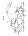
- reference numeral 1 denotes a lift truck used as a working machine, and the lift truck 1 is roughly constituted by a vehicle body 2 of a mobile wheel type, and a boom apparatus 18 that will be described after.
- the lift truck 1 employs the boom apparatus 18 to deliver freight goods from ground level to an elevated position, for example, after arriving at a job site by self-propulsion.
- Reference numeral 3 denotes a frame constituting the base of the vehicle body 2. As shown in Figs. 4 and 5, this frame 3 serves as a firm support structure member by employing, for example, a pair of vertical plates 4, 5 (a left vertical plate 4, a right vertical plate 5), which are formed of thick steel plates, and which are separated to the left and right sides and extended to the front and rear direction, and a bottom plate 6, which is formed of a thick plate same as the vertical plates 4, 5, and which couples (bonds) the vertical plates 4, 5 horizontally.
- a pair of vertical plates 4, 5 a left vertical plate 4, a right vertical plate 5
- a bottom plate 6 which is formed of a thick plate same as the vertical plates 4, 5, and which couples (bonds) the vertical plates 4, 5 horizontally.
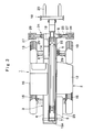
- Reference numeral 8 denotes a stabilizer mounting portion, provided at the front end side of the frame 3. As shown in Figs. 1 to 3, stabilizers 25, which will be described after, are connected to the stabilizer mounting portion 8 by pins to be extendable horizontally. Further, a cylinder mounting portion 9 is provided for the right vertical plate 5 of the frame 3. The cylinder mounting portion 9 is located between the stabilizer mounting portion 8 and a device support portion 11, and at a position consonant with the front wheel support portion 6A. The tilt correction cylinder 28, which will be described after, is to be connected by pins to the cylinder mounting portion 9.
- Reference numerals 10, 10 denote cab support portions provided for the left vertical plate 4 of the frame 3, and as shown in Figs. 4 and 5, the cab support portions 10, 10 are extended to the left (outwardly) from the middle of the external side face of the left vertical plate 4 to the front and rear directions.
- a cab 16 which will be described after, is supported by the individual cab support portions 10 and support seats 10A provided on the inner side face of the left vertical plate 4.
- Reference numeral 11 denotes a device support portion provided at the middle portion of the right vertical plate 5 to the front and rear directions.
- the device support portion 11 is projected to the right from the right vertical plate 5, and supports an engine as a prime mover, a radiator as a heat exchanger and other devices (not shown) from below.
- a device cover 12 is mounted on the device support portion 11, and is opened or closed for protection and maintenance of the engine.
- Reference numerals 13, 13 denote left and right front wheels, rotatably provided for the front portion of the frame 3 by an axle housing 14. As shown in Figs. 1 and 3, the left and right front wheels 13, 13 are rotatably mounted at the left and right ends of the axle housing 14 by vehicle shafts. When a rotational drive force powered by a hydraulic motor (not shown) is transmitted by the vehicle shaft, the left and right front wheels 13 together with the rear wheels 15 move the vehicle body 2. Further, the left and right front wheels 13 and the rear wheels 15 are all driven as a four-wheel drive guided by a steering handle (not shown) that is provided in the cab 16, which will be described after, so that the direction of travel of the vehicle body 2 can be controlled.
- a steering handle not shown
- the axle housing 14 is mounted by use of support pins (not shown) on the lower face of the front wheel support portion 6A, so that the axle housing 14 is horizontally displaceable relative to the bottom plate 6 of the frame 3.
- the axle housing 14 has a function to correct the horizontal tilt of the frame 3 of the lift truck 1 in cooperation with the tilt correction cylinder 28, which will be described after.
- Reference numerals 15, 15 denote left and right rear wheels rotatably mounted on the rear portion of the frame 3 through the axle housing. These left and right rear wheels 15 are also rotatably attached to the left and right ends of the axle housing by the vehicle shafts.
- the axle housing on the rear wheel side is also movably supported by the rear wheel support portion 6B of the bottom plate 6 by support pins (not shown). Then, a rotational drive force powered by the hydraulic motor for driving is transmitted by the vehicle shaft, and the left and right rear wheels drive the vehicle body 2 together with the front wheels 13. Further, the left and right rear wheels 15 and the front wheels 13 as a four-wheel drive are guided by the handle to control the direction of travel of the vehicle body 2.
- Reference numeral 16 denotes a cab that constitutes the operating section of the lift truck 1. As indicated by a chain double-dashed line in Figs. 4 to 7, the cab 16 is mounted on the left vertical plate 4 of the frame 3 by the cab support portion 10, and internally defines an operation chamber. Inside the cab 16 an operator's seat 17 on which an operator sits, the handle (not shown) for steering, a correction lever 49, operation levers 51, 52, 55, 62 and 63 are provided, which will be descried after.
- Reference numeral 17 denotes an operator's seat arranged in the cab 16. As shown in Fig. 1, the operator's seat 17 is mounted on the left vertical plate 4 of the frame 3 through the floor plate (not shown) of the cab 16. An operator who gets in and out of the cab 16 manually inclines the operation levers 51, 52, 55, 62 and 63, which will be described after, while the still in the operator' s seat 17.
- Reference numeral 18 denotes a boom apparatus for loading work that is provided liftably up and down on the rear side of the vehicle body 2.
- the boom apparatus 18 is roughly constituted by a boom 19 consisting a boss 19A at the base end that is liftably coupled with the rear upper end of the frame 3 (the vertical plates 4, 5) by the coupling pin 7 (see Fig. 4), and which is extended to the front and rear directions, and a fork 20 which serves as freight goods working tool that is rotatably mounted at the distal end of the boom 19.
- the boom 19 is constituted by a telescopic boom consisting of a plural number of steps (e.g., three steps). Furthermore, as indicated by a broken line in Fig. 2, a boom derricking cylinder 21 is located between the frame 3 and the boom 19.
- a hydraulic pump 97 which will be described after, through a directional control valve 36, the boom derricking cylinder 21 vertically lifts up and down the boom 19 with the coupling pin 7 in Fig. 2 as the center.
- Reference numeral 22 denotes a boom extension cylinder provided for the boom apparatus 18. As shown in Figs. 1 to 3, the boom extension cylinder 22 is located outside the boom 19, and extends or retracts the above described telescopic boom 19 in the longitudinal direction. In addition, a fork cylinder 23 (see Fig. 2) which serves as a work tool cylinder is located between the distal end of the boom 19 and the fork 20. The fork cylinder 23 is used to vertically turn the fork 20 at the distal end of the boom 19.
- the boom derricking cylinder 21, the boom extension cylinder 22 and the fork cylinder 23 constitute a boom hydraulic actuator that operates the boom apparatus 18.
- These cylinders 21, 22, 23 are extended or retracted by performing the supply or discharge of pressure oil from the hydraulic pump 97 through directional control valves 36, 37, 38 as shown in Fig. 21, which will be described after.
- Reference numeral 24 denotes a body stabilization apparatus provided at the front portion of the vehicle body 2. As shown in Fig. 1, the body stabilization apparatus 24 includes left and right stabilizer devices 25, 25 which are attached to the stabilizer mounting portion 8 of the frame 3, and the tilt correction cylinder 28 which corrects left and right inclinations of the vehicle body 2.
- the left and right stabilizers 25, 25 are constituted by stabilizer cylinders 26, 26, which serve as left and right stabilizer hydraulic actuators that are mounted on the front portion of the frame 3 through the stabilizer mounting portion 8, and left and right ground plates 27, 27, which contact the ground.
- the stabilizers 25 is extended from the stabilizer mounting portion 8 to the left and the right by the stabilizer cylinders 26, and the ground plates 27 contact the ground. Further, when the stabilizer cylinders 26 are retracted, the ground plates 27 of the stabilizers 25 are lifted vertically, high off the ground, to prevent the stabilizers 25 from interrupting the travel of the vehicle.
- Reference numeral 28 denotes a tilt correction hydraulic cylinder (hereinafter referred to as a tilt correction cylinder 28) that is mounted on the right vertical plate 5 of the frame 3 through the cylinder mounting portion 9. As shown in Fig. 1, the tilt correction cylinder 28 abuts upon the axle housing 14 on the front wheel 13 side so as to be able to be extended and retracted, and performs a correction (a frame leveling) for the left and right tilting of the frame 3.
- a tilt correction hydraulic cylinder hereinafter referred to as a tilt correction cylinder 28
- the frame 3 of the vehicle body 2 may be inclined to the left or right together with the axle housing 14 on the front wheel 13 side.
- the axle housing 14 is attached through the support pins to the front wheel support portion 6A of the bottom plate 6 so as to be rotatable horizontally.
- the tilt correction cylinder 28 need only be appropriately extended or retracted between the frame 3 and the axle housing 14, and the tilting of the vehicle body 2 can be corrected so that the frame 3 (the bottom plate 6) of the vehicle body 2 is horizontal relative to the axle housing 14 which is inclined on the slope.
- the body stabilization apparatus 24 employs the stabilizer cylinders 26 to extend the stabilizers 25 to the left and to the right and bring the ground plates 27 into contact with the ground, and employs the tilt correction cylinder 28 to correct the tilting of the vehicle body 2. In this manner, preventing the overturning of the vehicle body 2 is aimed at.
- Reference numeral 29 denotes a fuel tank that is provided at the rear portion of the frame 3, as shown in Fig. 1.
- the fuel tank 29 is mounted, from the side, at the rear portion of the right vertical plate 5 which serves as a part of the frame 3.
- the fuel tank 29 is provided as a hollow container that is made, for example, of a very strong synthetic resin material and has almost a rectangular shape, and is used to supply fuel to the engine of the device cover 12.
- reference numeral 31 denotes a lever/valve assembly adopted for this embodiment.
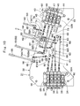
- the lever/valve assembly 31 is constituted by a mounting plate 32 which will be described after, a first control valve device 33 (directional control valves 36 to 39), a second control valve device 43 (directional control valves 46 to 48), a correction lever 49, a link mechanism 50, operation levers 51, 52, 55, 62, 63, and link mechanisms 53, 54, 56, 59 to 61.
- the lever/valve assembly 31 can be attached to or detached from the left vertical plate 4 of the frame 3 by using the mounting plate 32.
- the correction lever 49 and the operation levers 51, 52, 55, 62, 63 of the lever/valve assembly 31 are located so as to be projected from the upper end of the mounting plate 32 to the inside of the cab 16, and are manually inclined by an operator who is seated in the cab 16.
- the first and the second control valve devices 33, 43 are attached, at a distance, in the front and rear directions of the mounting plate 32. That is, the first control valve device 33 is located at the rear position of the boom apparatus 18 that is near the coupling pin 7 (the base end side of the boom 19).
- the second control valve device 43 which is positioned in front of the first control valve device 33 is located at a front position that is nearer the body stabilization apparatus 24 (the stabilizer mounting portion 8, the cylinder mounting portion 9).
- Reference numeral 32 denotes a mounting plate that constitutes the bracket of the lever/valve assembly 31.
- the mounting plate 32 is a flat plate made of flat steel, and is extended to the front and rear directions along the left vertical plate 4.
- the length of the mounting plate 32 to the front and the rear is about 100 to 130 cm, the width in the vertical direction is about 50 to 70 cm, and the thickness is about 4 to 8 mm.
- a first control valve mounting portion 32A located in front
- a second valve mounting portion 32B located at the rear
- a middle link mounting portion 32C located between the first and second control valve mounting portions 32A and 32B
- a lever mounting portion 32D located above the link mounting portion 32C.
- the mounting plate 32 of the lever/valve assembly 31 is attachably or detachably installed on the inner wall of the left vertical plate 4 (the right side face of the left vertical plate 4 as viewed from the rear of the vehicle) by use of installation bolts 92 which will be described after.
- the control valve mounting portion 32A of the mounting portion 32 is located at a position nearer the rear of the vehicle, while the other control valve mounting portion 32B is located at a position nearer the front of the vehicle.
- Reference numeral 33 denotes a first control valve device provided for the control valve mounting portion 32A of the mounting plate 32.
- the control valve device 33 is constituted by a lower joint plate 34 located on the lower side, an upper joint plate 35 located on the upper side, and the total four directional control valves 36, 37, 38, 39 used for a boom, which are laid between the joint plates 34, 35 as piled up state.
- the joint plates 34, 35 and the boom directional control valves 36 to 39 of the control valve device 33 are vertically laid as shown in Fig. 9, and the side faces (the left side faces as viewed from the rear of the vehicle) are brought into contact with and secured to the control valve mounting portion 32A of the mounting plate 32 by using bolts.
- the directional control valves 36 to 39 are connected by use of a parallel circuit as shown in Fig. 21, and a center bypass line 33A is connected to the hydraulic pump 97, which will be described after, through a pump line 40.
- the directional control valve 36 of the control valve device 33 performs the supply or discharge of pressure oil from the hydraulic pump 97, relative to the boom derricking cylinder 21 of the boom apparatus 18, so as to control the movement (extension and retraction) of the boom derricking cylinder 21.
- the directional control valve 37 of the control valve device 33 performs the supply and discharge of pressure oil from the hydraulic pump 97, relative to the boom extension cylinder 22, and permits the boom extension cylinder 22 to extend or retract the boom 19 in the longitudinal direction. Furthermore, the directional control valve 38 of the control valve device 33 performs the supply and discharge of pressure oil from the hydraulic pump 97, relative to the fork cylinder 23, so as to vertically turn the fork 20 at the distal end of the boom 19 shown in Fig. 1.
- a level cylinder 41 and the fork cylinder 23 are connected to the directional control valve 38 as parallel state.
- the level cylinder 41 When the level cylinder 41 is extended or retracted in association with the boom derricking cylinder 21, the level cylinder 41 automatically corrects the posture of the fork 20 relative to the lifting up and down movement of the boom 19 in Fig. 1.
- the front and rear inclinations of the fork 20 of the boom apparatus 18 are corrected by the level cylinder 41, so that the distal end of the fork 20 is maintained almost horizontal when the boom 19 is vertically elevated.
- the directional control valve 39 of the control valve device 33 is used to perform the supply and discharge of pressure oil from the hydraulic pump 97, relative to an extra hydraulic cylinder 42 in Fig. 21.
- Reference numeral 43 is a second control valve device provided for the control valve mounting portion 32B of the mounting portion 32.
- the control valve device 43 is constituted by a lower joint plate 44 located at the lower side, an upper joint plate 45 located at the upper side, and directional control valves 46, 47 used for stabilizers and a directional control valve 48 used for tilt correction, which are laid between these joint plates 44, 45 as piled up state.
- the joint plates 44, 45 and the directional control valves 46 to 48 of the control valve device 43 are vertically laid on each other, and their side faces (the left side faces as viewed from the rear of the vehicle) are brought into contact with and are secured to the control valve mounting portion 32B of the mounting plate 32 by using bolts. Further, for a reason that will be described after, as shown in Fig. 9, the directional control valves 46 to 48 of the control valve device 43 are located along a virtual line A-A that is inclined at an angle ⁇ from a line perpendicular to the vehicle.
- the directional control valves 46 to 48 are connected by use of a parallel circuit, as shown in Fig. 21, and a center bypass line 43A is connected to the center bypass line 33A of the first control valve device 33 via a hydraulic pipe 96.
- the directional control valves 46, 47 of the control valve device 43 perform the supply and discharge of pressure oil from the hydraulic pump 97, relative to the left and right stabilizer cylinders 26, 26 to control the movement (the extension and retraction) of the individual stabilizer cylinders 26.
- the directional control valve 48 of the control valve device 43 performs the supply and discharge of pressure oil from the hydraulic pump 97, relative to the tilt correction cylinder 28 to vertically extend or retract the tilt correction cylinder 28.
- the tilt correction cylinder 28 corrects the inclination of the vehicle body 2 shown in Fig. 1, so that the posture of the vehicle body 2 on a slope is stabilized.
- reference numeral 49 denotes an operation lever used for tilt correction (hereinafter referred to as a correction lever 49), which is provided for the lever mounting portion 32D of the mounting plate 32, so as to be capable of being inclined.
- the correction lever 49 is manually inclined to the left or to the right, indicated by an arrow a in Fig. 11.
- the correction lever 49 is coupled to the directional control valve. 48 via the link mechanism 50 which is an operation transmission member, and switches the directional control valve 48.
- the link mechanism 50 is constituted by a common support pin 66, spacers 70, stopper rings 71, an universal joint 72, rotary members 75, 77 and link rods 76, 78.
- Reference numerals 51, 52 denote operation levers for stabilizers (hereinafter referred to as stabilizer operation levers 51, 52).
- the stabilizer operation levers 51, 52 are attached to the lever mounting portion 32D of the mounting plate 32, at a distance to the rear of the correction lever 49, so as to be susceptible to being inclined. Further, as shown in Fig. 11, the stabilizer operation levers 51, 52 are located nearer each other in the horizontal direction, and manually inclined independently to the front or to the rear, as indicated by an arrow b.
- the stabilizer operation levers 51, 52 are coupled to the directional control valves 46, 47 individually by the link mechanisms 53, 54 which are operation transmission members .
- the stabilizer operation levers 51, 52 independently move the left and right stabilizers 25, 25 shown in Fig. 1.
- the link mechanisms 53, 54 in this case are constituted by common support pins 66, rotary members 67, 68, spacers 70, stopper rings 71, universal joints 72 and link rods 73, 74.
- Reference numeral 55 denotes an extra operation lever that is provided for the lever mounting portion 32D of the mounting plate 32, at a position to the rear of the stabilizer operation levers 51, 52, so as to be susceptible of being inclined.
- the operation lever 55 is linked to the directional control valve 39 of the first control valve device 33 through the link mechanism 56 which is an operation transmission member. And when the operation lever 55 is inclined to the front or to the rear directions (e.g., in the directions indicated by the arrow b in Fig. 11), the extra hydraulic cylinder 42 are operated as shown in Fig. 21.
- the link mechanism 56 which is located between the operation lever 55 and the directional control valve 39, includes a common support pin 66, spacers 70, stopper rings 71, universal joints 72, rotary members 79, 81 and link rods 80, 82.
- Reference numerals 57, 58 denote lever support members, which are provided for the lever mounting portion 32D of the mounting plate 32 at a position between the correction lever 49 and the stabilizer operation levers 51, 52.
- the lever support members 57, 58 are to be inclined by operation levers 62, 63 to the left or right directions and to the front or rear directions respectively.
- the lever support members 57, 58 are inclined independently in the same direction.
- the lever support members 57, 58 are integrally inclined in the same direction.
- cylindrical shaped stoppers 57A, 58A which a lock lever 64 is to be removably inserted are provided for the lever support members 57, 58.
- Reference numerals 59, 60, 61 denote link mechanisms that serve as operation transmission members attached to the link mounting portion 32C of the mounting plate 32. As shown in Figs. 10 to 12, the link mechanisms 59 to 61 are arranged between the lever support members 57, 58 and the directional control valves 36, 37, 38 to transmit control of the operation levers 62, 63 to the directional control valves 36, 37, 38.
- the link mechanism 59 here is constituted by a common support pin 66, a rotary member 83 and link rods 85, 86. And the inclining movement of the lever support member 58 to the front or rear directions (e.g. , the directions indicated by the arrow b in Fig. 11) by the operation lever 63 is transmitted to the directional control valve 36 via the link mechanism 59, so that the boom derricking cylinder 21 is controlled.
- the link mechanism 60 is arranged between the lever support member 57 and the directional control valve 37, and is constituted by a common support pin 66, a rotary member 84 and link rods 87, 88. And the inclining movement of the lever support members 57, 58 to the left or right directions (e.g., the directions indicated by the arrow a in Fig. 11) by the operation lever 62 or 63 is transmitted to the directional control valve 37 via the link mechanism 60, so that the boom extension cylinder 22 is controlled.
- the link mechanism 61 is arranged between the lever support member 57 and the directional control valve 38, and is constituted by a common support pin 66, a rotary member 89 and link rods 90, 91. And the inclining movement of the lever support member 57 to the front or rear directions (e.g., the directions indicated by the arrow b in Fig. 11) by the operation lever 62 is transmitted to the directional control valve 38 via the link mechanism 61, so that the fork cylinder 23 is controlled.
- Reference numerals 62, 63 denote a pair of left and right operation levers, which are provided for the lever support members 57, 58 and are located in the middle position between the correction lever 49 and the stabilizer operation levers 51, 52.
- the operation lever 62 is securely attached to the lever support member 57 and is coupled with the directional control valve 37 via the link mechanism 60, and is also coupled with the directional control valve 38 via the link mechanism 61.
- the other operation lever 63 is securely attached to the lever support member 58, as shown in Fig. 11, and is coupled to the directional control valve 36 via the link mechanism 59, while the operation lever 63 is also linked to the directional control valve 37 via the lever support member 57 and the link mechanism 60.
- Reference numeral 64 denotes a lock lever that constitutes a lock mechanism for locking the inclination manipulation of the operation levers 62, 63. As shown in Figs. 10 and 11, the lock lever 64 is attached to the lever mounting portion 32D of the mounting plate 32 through a support arm 65, and located at a position between the correction lever 49 and the operation levers 62, 63.
- the lock lever 64 locks the lever support members 57, 58, preventing any inclination of the operation levers 62, 63. Furthermore, when the lock lever is pulled up in the direction indicated by an arrow c in Fig. 10, the lock lever disengages the stoppers 57A, 58A, and permits the lever support members 57, 58 to be inclined together by the operation levers 62, 63.
- the second control valve device 43 (the directional control valves 46 to 48) is obliquely arranged along a virtual line A-A, which is inclined at an angle ⁇ from a line perpendicular to the vehicle.
- the correction lever 49 and the operation levers 51, 52, 55, 62, 63 of the lever/valve assembly 31 are arranged so as to be inclined away from each other, as shown in Figs. 8 to 12, while taking into account the usability to an operator in the cab 16.
- the upper ends of the correction lever 49 and the operation levers 51, 52, 55, 62, 63 are raised from the front to the rear of the frame 3, and arranged along a virtual line B-B which is inclined at an angle ⁇ from a line horizontal to the vehicle.
- the link mechanisms 50, 53, 54, 56, 59 to 61 are linked on the condition that their link joining portions (rotational points) are almost at a right angle, so that the link rods 73, 74, 78, 82, 86, 88, 91 are arranged to be positioned substantially linearly with the spools (not shown) of the directional control valves 46 to 48 and the directional control valves 36 to 39.
- a common support pin 66 is constituted by a shaft portion 66A having a large diameter and a small diameter portion 66B.
- the total length is about 100 to 150 mm, and the outer diameter is 13 to 16 mm.
- the shaft portion 66A of the common support pin 66 has a length in the axial direction of 90 to 130 mm, so that rotary members 67, 68 can be inserted with being arranged in the axial direction.
- circumferential grooves 66C, 66D, 66E, 66F in total are formed at intervals in the axial direction, and constitute stopper mounting portions whereat the stopper rings 71, which will be described after, are to be selectively attached.
- the interval between the circumferential grooves 66C, 66D is slightly greater than the lengths (sizes) in the axial direction of the rotary members 67, 68 and the interval between the circumferential grooves 66E, 66F is also slightly greater than the lengths (sizes) in the axial direction of the rotary members 67, 68.
- the interval between the circumferential grooves 66D, 66E is slightly greater than the plate thickness (the size in the axial direction) of the spacer 70.
- the small diameter portion 66B of the common support pin 66 penetrates the mounting plate 32 (the lever mounting portion 32D) of the lever/valve assembly 31 and is fixed by welding.
- the common support pin 66 is attached to the lever mounting portion 32D of the mounting plate 32 in the cantilever state. Further, the common support pin 66 is also used as a common part for the other link mechanisms 50, 56, 59 to 61.
- Reference numerals 67, 68 denote rotary members which serve as link members, that are fitted over the common support pin 66 while being arranged on the outer surface of the common support pin 66 in the axial direction.
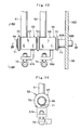
- the rotary members 67, 68 are cylindrical body while the external shapes are square, as shown in Figs. 13 and 14, and a pair of left and right collar bushes 69 are attached on the inner surface, as shown in Fig. 15.
- the inner surfaces of the collar bushes 69 serve as pin holes 69A that are fitted over the outer surface of the common support pin 66 (shaft portion 66A).
- the stabilizer operation levers 51, 52 are integrated with the rotary members 67, 68 by welding, and link levers 67A, 68A which are substantially L shaped project downward from the rotary members.
- Link rods 73, 74 which will be described after, are coupled with these link levers 67A, 68A via the universal joints 72.
- Reference numerals 70 denote spacers that are fitted over the outer surface of the common support pin 66 with the rotary members 67, 68. These spacers 70 are made of ring-shaped flat plates having a predesignated thickness. The spacers 70 are used to adjust a gap in the axial direction between the rotary members 67, 68 on the outer surface of the common support pin 66, and also to adjust a gap in the axial direction between the stopper ring 71 and the rotary members 67, 68.
- Reference numerals 71 denote stopper rings that serve as stopper tools that are selectively attached to the circumferential grooves 66C to 66F of the common support pin 66.
- these stopper rings 71 prevent the slipping off of the individual rotary members 67, 68 together with the spacers 70. Furthermore, the smooth rotation (revolution) of the rotary members 67, 68, which are fitted over the outer surface of the common support pin 66 (shaft portion 66A) through the collar bushes 69, is ensured, relative to the shaft 66A, by the spacers 70 and the stopper rings 71.
- Reference numerals 72 denote universal joints attached to the link levers 67A, 68A of the rotary members 67, 68. As shown in Fig. 12, these universal joints 72 are coupled with the ends of the link rods 73, 74 on one end, and as shown in Fig. 10, the other ends of the link rods 73, 74 are coupled with the directional control valves 46, 47, respectively.
- the directional control valves 46, 47 are separately switched via the link mechanisms 53, 54, by the stabilizer operation levers 51, 52.
- two common support pins 66 are arranged vertically, at an interval. Firstly, as for the upper common support pin 66 where the rotary member 75 is to be inserted, as shown in Fig. 17, the end of the shaft portion 66A that is nearer the small diameter portion 66B is fixed to the reverse face of the mounting portion 32 by welding. And the upper common support pin 66 is extended in the longitudinal direction (the front and the rear directions of the vehicle) of the mounting plate 32 so as to ensure that the correction lever 49 is inclined to the left or right directions with the rotary member 75.
- the small diameter portion 66B side is fixed to the mounting plate 32 in the cantilever state by welding.
- Reference numeral 75 denotes a rotary member that serves as a link member fitted over the upper common support pin 66, and is constituted substantially in the same manner as the rotary member 67 of the link mechanism 53 described above.
- collar bushes 69 are fitted (pushed in) along the inner surfaces.
- the stopper rings 71 which are mounted along the circumferential grooves 66D, 66F of the common support pin 66, hold the rotary member 75 on the outer surface of the common support pin 66 through the spacers 70, thereby the rotary member is prevented from slipping out.
- the correction lever 49 is integrated with the rotary member 75 by welding, and that the link lever 75A shaped like a flat plate is projected in the direction of the diameter of the common support pin 66.
- one end of the link rod 76 is connected to the link lever 75A through the universal joint 72, and the other end of the link rod 76 is rotatably connected to the link lever 77A of the rotary member 77, which will be described after.
- Reference numeral 77 denotes a rotary member that serves as a link member fitted over the lower common support pin 66, and is constituted substantially in the same manner as the rotary member 68 of the link mechanism 54 described above. As shown in Fig. 18, collar bushes 69, 69 are fitted (pushed in) along the inner surface. The rotary member 77 is fitted over the outer surface via the individual collar bushes 69, while the rotary member is shifted near the base end side (one side in the axial direction) of the common support pin 66.
- the link lever 77A which is a flat plate having a substantially trapezoidal shape, is provided for the rotary member 77, and is projected in the direction of the diameter of the common support pin 66.
- other end of the link rod 76 is rotatably coupled with an end of the link lever 77A and one end of the link rod 78 is rotatably coupled with the other end (the lower side) of the link lever 77A.
- the other end of the link rod 78 is coupled with the directional control valve 48, as shown in Fig. 10.
- the inclination control for the correction lever 49 is transmitted to the directional control valve 48 in Fig. 10 via the rotary member 75 (link lever 75A), the link rod 76, the rotary member 77 (link lever 77A) and the link rod 78 of the link mechanism 50 in Fig. 12.
- the link mechanism 56 employs common support pins 66, spacers 70, stopper rings 71, universal joints 72 as common parts, and also includes rotary members 79, 81 and link rods 80, 82.
- two common support pins 66 are vertically provided at an interval, as shown in Fig. 12.
- the small diameter portion 66B side is fixed to the mounting plate 32 by welding.
- the small diameter portion 66B side is fixed to the mounting plate 32 by welding.
- Reference numeral 79 denotes a rotary member that serves as a link member fitted over the upper common support pin 66, and is constituted substantially in the same manner as the rotary member 67 of the link mechanism 53 previously described. As shown in Fig. 19, collar bushes 69 are fitted (pushed in) along the inner surface. The rotary member 79 is fitted over the outer surface of the common support pin 66 via the collar bushes 69, while the rotary member is shifted to the distal end (the other side in the axial direction) of the common support pin 66.
- stopper rings 71, 71 which are mounted along the circumferential grooves 66D, 66F of the common support pin 66, holds the rotary member 79 on the outer surface of the common support pin 66, via the spacers 70, 70, thereby the rotary member is prevented from slipping out.
- the operation lever 55 is integrated with the rotary member 79 in this case by means such as welding, and that the link lever 79A shaped like a flat plate is projected in the direction of the diameter of the common support pin 66. Further, as shown in Fig. 12, one end of the link rod 80 is rotatably coupled with the link lever 79A, and the other end of the link rod 80 is rotatably coupled with the link lever 81A of the rotary member 81, which will be described after.
- Reference numeral 81 denotes a rotary member that serves as a link member fitted over the lower common support pin 66, and is constituted substantially in the same manner as the rotary member 68 of the link mechanism 54, as previously described. As shown in Fig. 20, collar bushes 69, 69 are fitted (pushed in) along the inner surface. The rotary member 81 is fitted over the outer surface via the individual collar bushes 69 , while the rotary member is shifted near the base end side (one side in the axial direction) of the common support pin 66.
- stopper rings 71, 71 which are mounted along the circumferential grooves 66C, 66E of the common support pin 66, hold the rotary member 81 on the outer surface of the common support pin 66, via the spacers 70, 70, thereby the rotary member is prevented from slipping out.
- the link lever 81A a flat plate having a substantially trapezoidal shape as shown in Fig. 12, is provided for the rotary member 81, and is projected in the direction of the diameter of the common support pin 66.
- other end of the link rod 80 is coupled rotatably with one end of the link lever 81A, and one end of the link rod 82 is rotatably coupled with the other end (the lower side) of the link lever 81A.
- the other end of the link rod 82 is coupled to the directional control valve 39, as shown in Fig. 10.
- the inclination control of the operation lever 55 is transmitted to the directional control valve 39 in Fig. 10 via the rotary member 79 (the link lever 79A), the link rod 80, the rotary member 81 (the link lever 81A) and the link rod 82 of the link mechanism 56 in Fig. 12.
- Reference numerals 83, 84 denote rotary members that serve as link members used for the link mechanisms 59, 60, and that constitute one part of the link mechanisms 59, 60 that couple the lever support members 57, 58 with the directional control valves 36, 37 as shown in Fig. 10. Further, substantially in the same manner as the rotary members 67, 68 shown in Fig. 13, the rotary members 83, 84 are fitted over the outer surface of a single common support pin 66, while being arranged in parallel in the axial direction.
- the rotary member 83 of the link mechanism 59 is rotatably coupled with the lever support member 58 via the link rod 85, and is also rotatably coupled with the directional control valve 36 in Fig. 10 via the link rod 86.
- the operating movement of the operation lever 63 for the inclination of the lever support member 58 to the front or the rear directions can be transmitted to the directional control valve 36 by the rotary member 83 via the link rods 85, 86.
- the rotary member 84 of the link mechanism 60 is rotatably coupled with the lever support member 57 via the link rod 87 and is also rotatably coupled with the directional control valve 37 in Fig. 10 via the link rod 88.
- the operating movement of the operation lever 62 or 63 for the inclination of the lever support members 57, 58 to the front or right directions can be transmitted to the directional control valve 37 by the rotary member 84 via the link rods 87, 88.
- Reference numeral 89 denotes a rotary member 89 that serves as another link member, and that constitutes a part of the link mechanism that couples the lever support member 57 with the directional control valve 38 as shown in Fig. 10.
- the rotary member 89 is attached, after having been shifted near the base end side (one side in the axial direction) of the common support pin 66, in substantially the same manner as the rotary member 81 in Fig. 20.
- the rotary member 89 of the link mechanism 61 is rotatably coupled with the lever support member 57 via the link rod 90, and is rotatably coupled with the directional control valve 38 in Fig. 10 via the link rod 91.
- the operating movement performed using the operation lever 62 to incline the lever support member 57 to the front or rear directions can be transmitted to the directional control valve 38 by the rotary member 89 via the link rods 90, 91.
- Reference numerals 92 denote installation bolts used to mount the lever/valve assembly 31 on the left vertical plate 4 of the frame 3. As shown in Figs. 6 to 9, these installation bolts 92 are screwed into screw seats 93, 94 which are welded on the inner side face of the left vertical plate 4. Thus, the installation bolts 92 attachably or detachably secure the mounting plate 32 of the lever/valve assembly 31 to the left vertical plate 4.
- a gap S (e.g., about 20 to 30 mm) is defined by the screw seats 93, 94, as shown in Figs. 6 and 7.
- the gap S has a function whereby heat from the control valve devices 33, 43 is externally discharged through the mounting plate 32.
- Reference numerals 95, 96 denote hydraulic pipes that connect the first and second control valve devices 33, 43 of the lever/valve assembly 31, and that are located between the first control valve device 33 and the second control valve device 43, as shown in Figs. 5 to 9. Of these two, the hydraulic pipe 95 connects the center bypass line 43A of the control valve device 43 to the center bypass line 33A of the control valve device 33, as shown in Fig. 21.
- the other hydraulic pipe 96 connects a low pressure side line 33B of the control device 33 with a low pressure side line 43B of the center bypass line 43A in Fig. 21 that is arranged downstream of the directional control valve 48.
- the hydraulic pipe 96 is connected via a hydraulic pipe 99 to an operating oil tank 98.
- Reference numeral 97 denotes a hydraulic pump that serves as a hydraulic source, together with the operating oil tank 98.
- the hydraulic pump 97 is located between the vertical plates 4, 5 in Fig. 5 and above the bottom plate 6, and is rotated by an engine (not shown) mounted on the device support portion 11. Further, the operating oil tank 98 is located, for example, outside the left vertical plate 4 and below the cab 16. As shown in Fig. 21, the hydraulic pump 97 sucks operating oil from the operating oil tank 98 and supplies pressure oil to the pump line 40 under high pressure. The supply and discharge of this pressure oil through the directional control valves 36 to 39 and 46 to 48 is performed relative to the individual cylinders 21 to 23, 42, 26, 28, and so forth.
- Reference numeral 99 denotes another hydraulic pipe located between the low pressure side line 43B of the control valve device 43 and the operating oil tank 98.
- the hydraulic pipe 99 is also connected to the low pressure side line 33B of the control valve device 33 via the hydraulic pipe 96, and connects these low pressure side lines 33B, 43B to the operating oil tank 98.
- the hydraulic pump 97 are rotated. Then, the supply and discharge of pressure oil forced out by the hydraulic pump 97 is performed relative to a driving hydraulic motor (not shown) for driving the front wheels 13 and the rear wheels 15, while the steering operation by using the handle is performed to steer the front wheels 13 and the rear wheels 15. As a result, the lift truck 1 is self-propelled while traveling to a work site.
- the left and right stabilizers 25, 25 in Fig. 1 are elevated, and the respective ground plates 27 are positioned, widely separated from the ground to prevent the stabilizers 25 from interfering with the movement of the vehicle.
- the fork 20 can be positioned to slide under the freight goods. Furthermore, at this time, when the operator in the cab 16 manually inclines the operation lever 62, the inclining of the operation lever 62 is transmitted via the lever support member 57 and the link mechanism 61 to the directional control valve 38.
- the directional control valve 38 can be changed from the neutral position shown in Fig. 21, and the supply and discharge of pressure oil by the hydraulic pump 97 can be performed for the fork cylinder 23, so that the fork cylinder 23 is driven in the extended direction. Then, when the fork cylinder 23 has been partially extended, for example, the fork 20 can be turned slightly, vertically, at the distal end of the boom apparatus 18 in Fig. 1, and the freight goods can be positioned on and stably supported by the fork 20.
- the operator in the cab 16 need only incline the correction lever 49 which serves as an operation lever for the correction of inclination, to change the directional control valve 48 which is coupled with the correction lever 49 via the link mechanism 50.
- the directional control valve 48 is switched, the supply and discharge of pressure oil by the hydraulic pump 97 can be performed for the tilt correction cylinder 28.
- the tilt correction cylinder 28 can be extended or retracted, so that the left or right tilting of the frame 3 can be corrected (frame leveling).
- the left and right stabilizers 25, 25 For a loading operation during which freight goods are carried to an elevated level (a high location) by using the boom apparatus 18 while the freight goods are borne by the fork 20, an external force that can overturn the vehicle may be applied due to the weight of the freight goods.
- the left and right stabilizers 25, 25 In order to avoid overturning the vehicle, the left and right stabilizers 25, 25 must be positioned so they are extended further to the left and right than the respective stabilizer cylinders 26, as shown in Fig. 1.
- the operator in the cab 16 inclines the stabilizer operation levers 51, 52.
- the operation forces produced by the operation levers 51, 52 are transmitted to the directional control valves 46, 47 via the link mechanisms 53, 54, so that the directional control valves 46, 47 are switched, and the left and right stabilizer cylinders 26, 26 are driven in the extended directions.
- the individual stabilizers 25 of the lift truck 1 can be extended to the left and right directions by the stabilizer cylinders 26, and the ground plates 27 can be brought into contact with the ground.
- the stable state of the vehicle body 2 can be maintained during a loading operation, and the overturning of the vehicle body 2 can be provided.
- the operator in the cab 16 manipulates the operation levers 62, 63 while the lock lever 64 is disengaged, as described above.
- this inclination is transmitted to the directional control valve 36 via the lever support member 58 and the link mechanism 59, and the boom derricking cylinder 21 in Figs. 2 and 21 is extended or retracted, so that the boom 19 of the boom apparatus 18 can be lifted up and down vertically (hoisting).
- the operator in the cab 16 inclines the operation lever 62 or 63 to retract the boom 19 of the boom apparatus 18. Further, by inclining the operation lever 63, the boom 19 is moved downward (descends). Through this operation, as shown in Fig. 1, the boom apparatus 18 can be positioned and stored on the frame 3.
- the first control valve device 33 (the directional control valves 36 to 39), the second control valve device 43 (the directional control valve 46 to 48), the correction lever 49, the operation levers 51, 52, 55, 62, 63, the link mechanisms 50, 53, 54, 56, 59 to 61, and so forth, are mounted in advance on the mounting plate 32 to construct the lever/valve assembly 31.
- the lever/valve assembly 31 which is preliminarily constructed in this manner, is to be attachably or detachably mounted on the left vertical plate 4, from inside the frame 3, by use of the mounting plate 32 and a plural number of installation bolts. Because of this arrangement, the operation for mounting the control valve devices 33, 43, the correction lever 49, the operation levers 51, 52, 55, 62, 63, the link mechanisms 50, 53, 54, 56, 59 to 61 on the frame 3 of the vehicle body 2 can be efficiently performed.
- the preliminarily constructed lever/valve assembly 31 is attached via the mounting plate 32 to the left vertical plate 4 of the frame 3, unlike the conventional example, the process for attaching directional control valves to the frame and the process for mounting operation levers on the frame need not be performed separately. Furthermore, the mounting plate 32 of the lever/valve assembly 31 need only be mounted on the left vertical plate 4 of the frame 3, so that the control valve devices 33, 43, the correction lever 49, the operation levers 51, 52, 55, 62, 63 can be collectively mounted on the frame 3. As a result, the assembly work efficiency can be improved.
- fine adjustment can also be easily performed for the link mechanisms 50, 53, 54, 56, 59 to 61, which are provided for the link mounting portion 32C of the mounting plate 32. That is, for the link mechanisms 50, 53, 54, 56, 59 to 61, fine adjustments can be easily performed, for example, for the link length of the link rods 73, 74, 76, 78, 80, 82, 85 to 88, 90, 91, and the movements of the individual links can be smoothly adjusted.
- the adjustment for smoothing the movements of the link mechanisms 50, 53, 54, 56, 59 to 61 can be easily performed in a large work space when the lever/valve assembly 31 has been preliminarily constructed. Furthermore, at this preliminary assembly stage, fine adjustments for the movements of the directional control valves 36 to 39, 46 to 48 can also be easily performed.
- the lever/valve assembly 31 can be fixed to the inner side face of the left vertical plate 4 of the frame 3, in the transverse direction (the direction from either the left or the right) by use of the mounting plate 32 and installation bolts 92.
- the process for mounting the lever/valve assembly 31 on the frame 3 of the vehicle body 2 can be smoothly performed, and the efficiency of the assembly operation can be improved.
- the lever/valve assembly 31 is designed by the following construction, namely the link mechanisms 50, 53, 54, 56, 59 to 61 are mounted on the single mounting plate 32, together with the correction lever 49, the operation levers 51, 52, 55, 62, 63 and the directional control valves 36 to 39, 46 to 48. Therefore, the entire lever/valve assembly 31, which includes the first control valve device 33 (the directional control valves 36 to 39) and the second control valve device 43 (the directional control valves 46 to 48), can be made compactly, and assembly errors can also be reduced.
- the link mechanisms 50, 53, 54, 56, 59 to 61 are attached in advance to the single mounting plate 32 to construct the lever/valve assembly 31, the assembly operation for the control valve devices 33, 43 and the operation levers 51, 52, 55, 62, 63 can be efficiently performed. As a result, the efficiency of the vehicle assembly operation can be considerably increased.
- the cab 16 into which the operator gets in and out is provided with the left vertical plate 4 on which the lever/valve assembly 31 is mounted, and the correction lever 49, the operation levers 51, 52, 55, 62, 63 are arranged inside the cab 16.
- the usability to the operator in the cab 16 can be improved.
- an operator in the cab 16 can switch the directional control valves 36 to 39, 46 to 48 by manually inclining the correction lever 49 and the operation levers 51, 52, 55, 62, 63, so that the supply and discharge control (operation) of pressure oil for the individual cylinders 21 to 23, 26, 28, 42 can be smoothly performed.
- the first control valve device 33 which includes the directional control valves 36 to 39 used for a boom
- the second control valve device 43 which includes the directional control valves 46, 47 used for stabilizers and the directional control valve 48
- the first control valve device 33 is located at a position near the coupling pin 7 (near the base end of the boom 19) of the boom apparatus 18, while the second control valve device 43 is located at a position near the body stabilization apparatus 24 (the stabilizer mounting portion 8 and the cylinder mounting portion 9).
- the lengths of the individual hydraulic pipes which connect the first control valve device 33 (the directional control valves 36 to 39) to the cylinders 21 to 23, 41, 42 of the boom apparatus 18, can be shorter than those of the conventional examples. Further, the lengths of the individual hydraulic pipes, which connect the second control valve device 43 (the directional control valves 46 to 48) and the cylinders 26, 28 of the body stabilization apparatus 24, can also be actually shortened.
- one of the hydraulic pipes which is to be connected to the first control valve device 33 (the directional control valves 36 to 39), is arranged toward the rear from the position of the control valve device 33 in order to be extended to the cylinders 21 to 23, 41, 42 of the boom apparatus 18.
- the other hydraulic pipe which is to be connected to the second control valve device 43 (the directional control valves 46 to 48), is arranged toward the front from the position of the control valve device 43 in order to be extended to the cylinders 26, 28 of the body stabilization apparatus 24.
- the individual hydraulic pipes thus arranged will not contact or interfere with the link mechanisms 50, 53, 54, 56, 59 to 61 which are located between the directional control valves 36 to 39 and the directional control valves 46 to 48.
- the movements of the link mechanisms 50, 53, 54, 56, 59 to 61 can be protected from being adversely affected by the pulsating motion of pressure oil that flows through the hydraulic pipes, and the stable movement of the individual links can be maintained.
- the length can be shortened for one hydraulic pipe that connects the first control valve device 33 and the individual cylinders 21 to 23, 41, 42 of the boom apparatus 18, and for the other hydraulic pipe that connects the second control valve device 43 to the cylinders 26, 28 of the body stabilization apparatus 24. Therefore, the number of pipe hooks (not shown) can be reduced that are used at the positions en route in the longitudinal direction of each hydraulic pipe, and the number of parts can be reduced. Thus, the hydraulic piping operation can be simplified, and the vehicle assembly work efficiency can be improved.
- the lock lever 64 for regulating the manipulation of the operation levers 62, 63 are provided for the mounting plate 32 of the lever/valve assembly 31.
- the lock lever 64 can be included in the lever/valve assembly 31 constituted by the control valve devices 33, 43 and the operation levers 51, 52, 55, 62, 63.
- the entire lever/valve assembly 31 can be compactly made. Further, when the lock lever 64 is operated, erroneous operations of the operation levers 62, 63 can be prevented, so that operating safety is ensured and reliability is increased.
- the rotary members 67, 68 for example, of the link mechanisms 53, 54 shown in Figs. 13 to 15 are fitted over the outer surface of the common support pin 66 that is supported by the mounting plate 32 in a cantilever manner, while the rotary members are arranged in line in the axial direction (first usage form).
- the rotary member 77 of the link mechanism 50 in Fig. 18 is fitted over the outer surface of the common support pin 66 that is supported by the mounting plate 32 in the cantilever manner, while the rotary member is shifted to one side in the axial direction (near the base end of the common support pin 66) (second usage form).
- the rotary member 79 of the link mechanism 59 in Fig. 19 is fitted over the outer surface of the common support pin 66 that is supported by the mounting plate 32 in the cantilever manner, while the rotary member is shifted to the other side in the axial direction (near the distal end of the common support pin 66) (third usage form).
- the rotary member 81 of the link mechanism 56 in Fig. 20 is fitted according to the second usage form where the rotary member is shifted to near the base end of the common support pin 66.
- the single common support pin 66 can be used as a common part. Also for the other link mechanisms 59, 60, 61, the rotary members 83, 84, 89 in Fig. 12 can be fitted over the respective common support pins 66 by selecting one of the previously described first to third usage forms.
- the outer surface of the shaft portion 66A that is near the small diameter portion 66B may be fixed to the reverse face of the mounting plate 32 by welding.
- the common support pin 66, the spacers 70 and the stopper rings 71 are employed as common parts for the plural number of link mechanisms 50, 53, 54, 56, 59 to 61, the number of parts can be reduced, and parts management can be simplified. As a result, the erroneous assembly of the common support pin 66 can be prevented, and extra labor and time are not required for the process for attaching the common support pin 66. Therefore, the efficiency of the assembly operation can be improved.
- a second embodiment of the present invention is shown in Fig. 22, and the characteristic of this embodiment is an arrangement wherein operating valves of a hydraulic pilot type are employed to switch directional control valves. It should be noted that, in this embodiment the same reference numerals are provided for the same components as those in the first embodiment described above, and no further explanation for them will be given.
- reference numeral 101 denotes a lever/valve assembly that is adopted for this embodiment, and is constructed substantially in the same manner as is the lever/valve assembly 31 described in the first embodiment.
- First and second control valve devices 103, 110 which will be described after, and pressure reducing valve type pilot operating valves 116, 119 , 120, 125, 128, 129 are provided for a mounting plate 102 that serves as a bracket.
- the mounting plate 102 of the lever/valve assembly 101 has almost the same shape as that of the mounting plate 32 described in the first embodiment. However, provided for the mounting plate 102 in this embodiment are first and second control valve mounting portions 102A, 102B that are located on either side in the front and rear directions, and an operating valve mounting portion 102C that is located at the upper side.
- Reference numeral 103 denotes a first control valve device that is attached to the control valve mounting portion 102A of the mounting plate 102, and that is constructed substantially in the same manner as the control valve device 33 described in the first embodiment. That is, the control valve device 103 includes lower and upper joint plates 104, 105, and a total of four directional control valves 106, 107, 108, 109, which are arranged as though piled up each other between the joint plates 104, 105. However, the control valve device 103 in this case is different in that the directional control valves 106 to 109 are constituted by a hydraulic pilot type directional control valves.
- Reference numeral 110 denotes a second control valve device that is provided for the control valve mounting portion 102B of the mounting plate 102, and that is constructed substantially in the same manner as the control valve device 43 described in the first embodiment. That is, the control valve device 110 includes lower and upper joint plates 111, 112, and a total of three directional control valves 113, 114, 115, which are piled up each other between these joint plates 111, 112. However, the control valve device 110 in this case is different in that the directional control valves 113 to 115 are constituted by a hydraulic pilot type directional control valves.
- Reference numeral 116 denotes a pilot operating valve that serves as signal output means provided for the operating valve mounting portion 102C of the mounting plate 102.
- a correction lever 117 which is substantially the same as the correction lever 49 (the operation lever for tilt correction) described in the first embodiment, is operatably provided for the pilot operating valve 116. Further, the output side of the pilot operating valve 116 is connected to the directional control valve 115 via a pair of pilot pipes 118A, 118B that serve as signal transmission means.
- Reference numerals 119, 120 denote pilot operating valves that are provided as another signal output means for the operating valve mounting portion 102C of the mounting plate 102.
- Operation levers 121, 122 which are substantially the same as the stabilizer operation levers 51, 52 described in the first embodiment, are operatably provided for the pilot operating valves 119, 120.
- the output side of the pilot operating valve 119 is connected to the directional control valve 113 via pilot pipes 123A, 123B that are signal transmission means.
- the output side of the pilot operating valve 120 is connected to the directional control valve 114 via pilot pipes 124A, 124B that are signal transmission means.
- pilot pressures that are consonant with the inclination operations of the operation levers 121, 122 is transmitted from the pilot operating valves 119, 120 to the directional control valves 113, 114, these directional control valves 113, 114 are switched in consonance with the inclination operation of the operation levers 121, 122.
- Reference numeral 125 denotes a pilot operating valve that is provided as another signal output means for the operating valve mounting portion 102C of the mounting plate 102.
- An operation lever 126 which is substantially the same as the operation lever 55 described in the first embodiment, is openatably provided for the pilot operating valve 125. Further, the output side of the pilot operating valve 125 is connected to the directional control valve 109 via pilot pipes 127A, 127B, which are signal transmission means.
- Reference numerals 128, 129 denote pilot operating valves that are provided as other signal output means for the operating valve mounting portion 102C of the mounting plate 102.
- Operating levers 130, 131 which are substantially the same as the operation levers 62, 63 described in the first embodiment, are openatably provided for the pilot operating valves 128, 129.
- the output side of the pilot operating valve 128 is connected to the directional control valve 108 via pilot pipes 132A, 132B, which are signal transmission means, and is also connected to the directional control valve 107 via pilot pipes 133A, 133B, which are signal transmission means.
- the output side of the pilot operating valve 129 is connected to the directional control valve 106 via pilot pipes 134A, 134B, which are signal transmission means, and is also connected to the directional control valve 107 via the pilot pipes 133A, 133B.
- the pilot operating valves 128, 129 supply a pilot pressure to the directional control valves 108, 106, and independently switch the directional control valves 108, 106. Further, when the operation levers 130, 131 are inclined to the left or right directions, the pilot operating valves 128, 129 supply to the directional control valve 107 a pilot pressure that is consonant with either inclination operation, and switches the directional control valve 107.
- the lever/valve assembly 101 can be constructed by using the control valve devices 103, 110, and the pilot operating valves 116, 119, 120, 125, 128, 129, and almost the same operating effects as obtained in the first embodiment can be acquired. Further, the first control valve device 103 which includes the directional control valves 106 to 109, and the second control valve device 110 which includes the directional control valves 113 to 115, can be attached through the mounting plate 102 at an interval toward the front and the rear of the frame 3 (the left vertical plate 4).
- the pilot operating valves 116, 119, 120, 125, 128, 129 which serve as signal output means, and the directional control valves 106 to 109, 113 to 115 can be connected by the pilot pipes 118A, 118B, 123A, 123B, 124A, 124B, so that the link mechanisms 50, 53, 54, 56, 59 to 61 described in the first embodiment are not required.
- the directional control valves 106 to 109, 113 to 115 have been regarded as a hydraulic pilot type directional control valve, and the pilot operating valves 116, 119, 120, 125, 128, 129 have been employed as example signal output means.
- the present invention is not limited to this, and directional control valves, for example, may be proportional solenoid control valves, and electric levers may be employed as signal output means.
- the link mechanisms 50, 53, 54, 56, 59 to 61 have been employed as example operation transmission members for the lever/valve assembly 31.
- the present invention is not limited to this, and an operation transmission member made of push-pull wire may be employed to transmit the manipulation of the operation levers to the directional control valves.
- the common support pins 66 used as common parts have been formed having a length such that two link members (e.g. , the rotary members 67, 68) can be arranged in line in the axial direction.
- the present invention is not limited to this, and a common support pin 141 according to a modification shown in Fig. 23 is also available.
- the common support pin 141 may be formed with a length that permits three link members to be fitted, while arranged in line in the axial direction.
- the common support pin 141 is constituted by a shaft portion 141A having a large diameter and a small diameter portion 141B.
- the shaft portion 141A is elongated, and in the axial direction has a length that permits three link members (e.g. , the rotary members 67, 68) to be fitted over the common support pin, while arranged in line in the axial direction. Therefore, on the outer surface of the shaft portion 141A, for example, a total of six circumferential grooves 141C, 141D, 141E, 141F, 141G, 141H are formed at intervals in the axial direction.
- the pair of left and right collar bushes 69, 69 have been fitted along the inner surfaces of the rotary members 67, 68, which serve as link members.
- a common support pin may be inserted through a roller bearing into the inner surfaces (pin holes) of the link members of the rotary members 67, 68.
- the first and second control valve devices 33, 43 have been mounted on the mounting plate 32 of the lever/valve assembly 31 at an interval toward the front and rear directions.
- the present invention is not limited to this, for example, one or more directional control valves and one or more operation levers which switch the directional control valves, may be attached to a single bracket (one mounting plate) to construct the lever/valve assembly. And a plural number of directional control valves may be constructed as a control valve device serving as a single block. This also applies for the second embodiment.
- the lift truck 1 used for a loading operation has been employed as an example working machine.
- the present invention is not limited to this, and can be widely applied for another working machine, such as a hydraulic excavator, a hydraulic crane or a wheel loader, that includes a boom apparatus wherein a hydraulic actuator for a boom is operated by switching directional control valves by use of operation levers.
Landscapes
- Engineering & Computer Science (AREA)
- Structural Engineering (AREA)
- Transportation (AREA)
- Civil Engineering (AREA)
- Mechanical Engineering (AREA)
- Life Sciences & Earth Sciences (AREA)
- Geology (AREA)
- Mining & Mineral Resources (AREA)
- General Engineering & Computer Science (AREA)
- Chemical & Material Sciences (AREA)
- Combustion & Propulsion (AREA)
- Forklifts And Lifting Vehicles (AREA)
Applications Claiming Priority (3)
| Application Number | Priority Date | Filing Date | Title |
|---|---|---|---|
| JP2004100096A JP2005280949A (ja) | 2004-03-30 | 2004-03-30 | 作業機械 |
| JP2004100097A JP2005284892A (ja) | 2004-03-30 | 2004-03-30 | 作業機械 |
| PCT/JP2005/005980 WO2005095258A1 (fr) | 2004-03-30 | 2005-03-22 | Machine de travail |
Publications (1)
| Publication Number | Publication Date |
|---|---|
| EP1733997A1 true EP1733997A1 (fr) | 2006-12-20 |
Family
ID=35063654
Family Applications (1)
| Application Number | Title | Priority Date | Filing Date |
|---|---|---|---|
| EP05721629A Withdrawn EP1733997A1 (fr) | 2004-03-30 | 2005-03-22 | Machine de travail |
Country Status (3)
| Country | Link |
|---|---|
| US (1) | US20080314854A1 (fr) |
| EP (1) | EP1733997A1 (fr) |
| WO (1) | WO2005095258A1 (fr) |
Cited By (3)
| Publication number | Priority date | Publication date | Assignee | Title |
|---|---|---|---|---|
| WO2009042097A1 (fr) * | 2007-09-27 | 2009-04-02 | Caterpillar Inc. | Centre d'entretien monté sur châssis ayant un boîtier amovible séparément |
| EP3103758A1 (fr) * | 2015-06-10 | 2016-12-14 | SKS Toijala Works Oy | Agencement de la structure du châssis d'une machine de préhension mobile |
| RU170998U1 (ru) * | 2016-12-27 | 2017-05-17 | Публичное акционерное общество "Уральский завод тяжелого машиностроения" | Экскаватор одноковшовый гидравлический |
Families Citing this family (9)
| Publication number | Priority date | Publication date | Assignee | Title |
|---|---|---|---|---|
| JP5404680B2 (ja) * | 2011-03-17 | 2014-02-05 | 日立建機株式会社 | 建設機械の作動油タンク取り付け構造 |
| JP5546484B2 (ja) * | 2011-03-17 | 2014-07-09 | 日立建機株式会社 | ミニショベルの燃料タンク固定構造 |
| US12036861B2 (en) * | 2015-03-10 | 2024-07-16 | Nathan Bunting | All-terrain construction equipment and methods |
| USD817750S1 (en) | 2015-08-20 | 2018-05-15 | Caterpillar Inc. | Bracket cover |
| US10000244B2 (en) * | 2016-02-17 | 2018-06-19 | Wacker Neuson Production Americas, L.L.C. | Tiltable cabin |
| US11035096B1 (en) | 2017-03-29 | 2021-06-15 | Nathan Bunting | Construction equipment and methods |
| CN106986285B (zh) * | 2017-04-30 | 2022-07-26 | 安徽好运机械有限公司 | 一种用于伸缩臂越野车的倾翻机构 |
| US20240240658A1 (en) * | 2023-01-17 | 2024-07-18 | Narendra Gupta | Hydraulic power pack module |
| CN116281760A (zh) * | 2023-02-09 | 2023-06-23 | 三一海洋重工有限公司 | 一种车架及叉车 |
Family Cites Families (34)
| Publication number | Priority date | Publication date | Assignee | Title |
|---|---|---|---|---|
| US2345223A (en) * | 1940-08-21 | 1944-03-28 | Midland Steel Prod Co | Control apparatus |
| US2979081A (en) * | 1959-08-17 | 1961-04-11 | Deere & Co | Control mechanism |
| US3492889A (en) * | 1968-03-18 | 1970-02-03 | Massey Ferguson Inc | Adjustable control stand |
| US3972249A (en) * | 1975-08-11 | 1976-08-03 | Allis-Chalmers Corporation | Multiple lever control console |
| US4051860A (en) * | 1975-12-15 | 1977-10-04 | Massey-Ferguson Inc. | Valve control mechanism |
| GB1510170A (en) * | 1975-12-19 | 1978-05-10 | Bamford Excavators Ltd J | Fluid control valve assembly |
| US4126056A (en) * | 1977-07-11 | 1978-11-21 | Caterpillar Tractor Co. | Control lever assembly |
| JPS55104532U (fr) * | 1979-01-17 | 1980-07-21 | ||
| US4349046A (en) * | 1980-09-15 | 1982-09-14 | International Harvester Co. | Hydraulic valve block mounting |
| JPS5850605U (ja) * | 1981-09-30 | 1983-04-06 | 株式会社クボタ | トラクタにおけるバルブ操作構造 |
| JPS598999U (ja) * | 1982-07-06 | 1984-01-20 | 日産自動車株式会社 | 産業車両における荷役切換弁のストツパ装置 |
| US4711467A (en) * | 1986-01-13 | 1987-12-08 | Clark Equipment Company | Method and means for lift truck assembly and servicing |
| JPS62175271A (ja) * | 1986-01-13 | 1987-07-31 | クラ−ク・エクイプメント・カンパニ− | リフトトラツクとその製造方法 |
| US4991700A (en) * | 1988-03-15 | 1991-02-12 | Mitsubishi Jidosha Kogyo Kabushiki Kaisha | Selector lever apparatus for vehicle |
| JP2558630Y2 (ja) * | 1990-11-29 | 1997-12-24 | 株式会社クボタ | バックホーの油圧操作構造 |
| US5639119A (en) * | 1992-12-04 | 1997-06-17 | Trak International, Inc. | Forklift stabilizing apparatus |
| US5383680A (en) * | 1992-12-21 | 1995-01-24 | Cadillac Gage Textron Inc. | Anti-roll system for wheeled vehicles |
| GB9408790D0 (en) * | 1994-05-04 | 1994-06-22 | Caterpillar Inc | Work vehicle |
| JPH09137472A (ja) * | 1995-11-10 | 1997-05-27 | Kubota Corp | バックホウ |
| US5944130A (en) * | 1997-11-04 | 1999-08-31 | Caterpillar Inc. | Trunnion mounted drive train arrangement |
| US6152253A (en) * | 1998-04-28 | 2000-11-28 | Gehl Company | Drive train system for a construction-type vehicle |
| US6367574B1 (en) * | 1999-08-20 | 2002-04-09 | Venture Products, Inc. | Multi-function control system for articulated vehicle |
| US6557586B1 (en) * | 1999-08-27 | 2003-05-06 | Crown Equipment Corporation | Control handle support and valve linkage assembly |
| US6757958B1 (en) * | 2000-05-11 | 2004-07-06 | Jlg Omniquip, Inc. | Load handler with modular frame assembly |
| US6543562B1 (en) * | 2000-08-29 | 2003-04-08 | Caterpillar Inc | Central service module |
| JP2002161550A (ja) * | 2000-11-24 | 2002-06-04 | Kubota Corp | 旋回作業機 |
| GB2369810B (en) * | 2000-12-09 | 2004-07-14 | Caterpillar Inc | Work machine arrangement |
| US20020093153A1 (en) * | 2001-01-15 | 2002-07-18 | Scotese Michael J. | Axle stabilization system |
| FR2822859B1 (fr) * | 2001-03-29 | 2003-07-18 | Volvo Compact Equipment Sa | Engin de travaux publics polyvalent du type chargeuse- pelleteuse |
| DE10252592A1 (de) * | 2001-11-12 | 2003-06-18 | Otto Herman Seyfarth | Integriertes pneumatisches Leitungssystem |
| US6688328B2 (en) * | 2002-01-07 | 2004-02-10 | Force America Inc. | Valve and tank enclosure assembly |
| WO2003080497A1 (fr) * | 2002-03-22 | 2003-10-02 | Hitachi Construction Machinery Co., Ltd. | Engin de travail autopropulse |
| JP4080974B2 (ja) * | 2003-08-12 | 2008-04-23 | 株式会社クボタ | ホイール式作業機 |
| US7401673B2 (en) * | 2005-09-15 | 2008-07-22 | Komatsu Ltd. | Frame structure for construction machine |
-
2005
- 2005-03-22 US US10/588,384 patent/US20080314854A1/en not_active Abandoned
- 2005-03-22 EP EP05721629A patent/EP1733997A1/fr not_active Withdrawn
- 2005-03-22 WO PCT/JP2005/005980 patent/WO2005095258A1/fr not_active Ceased
Non-Patent Citations (1)
| Title |
|---|
| See references of WO2005095258A1 * |
Cited By (3)
| Publication number | Priority date | Publication date | Assignee | Title |
|---|---|---|---|---|
| WO2009042097A1 (fr) * | 2007-09-27 | 2009-04-02 | Caterpillar Inc. | Centre d'entretien monté sur châssis ayant un boîtier amovible séparément |
| EP3103758A1 (fr) * | 2015-06-10 | 2016-12-14 | SKS Toijala Works Oy | Agencement de la structure du châssis d'une machine de préhension mobile |
| RU170998U1 (ru) * | 2016-12-27 | 2017-05-17 | Публичное акционерное общество "Уральский завод тяжелого машиностроения" | Экскаватор одноковшовый гидравлический |
Also Published As
| Publication number | Publication date |
|---|---|
| US20080314854A1 (en) | 2008-12-25 |
| WO2005095258A1 (fr) | 2005-10-13 |
Similar Documents
| Publication | Publication Date | Title |
|---|---|---|
| US20140271078A1 (en) | Lift arm structure with an articulated knee portion | |
| EP1997964B1 (fr) | Machine de travail avec une cabine rotative | |
| US20080314854A1 (en) | Working Machine | |
| CN113348283B (zh) | 用于动力机械特别是迷你装载机的机械自调平提升臂结构 | |
| CN1863971A (zh) | 多功能作业机械 | |
| JP4687152B2 (ja) | 作業車両におけるリフトアーム装置、及びそれを備える作業車両 | |
| KR20070059988A (ko) | 작업 차량 및 스키드 스티어 로더 | |
| US6539650B2 (en) | Swivel mounting for quick attachment bracket | |
| WO2017051933A1 (fr) | Véhicule de terrassement | |
| EP1997962B1 (fr) | Procédé pour la commande d'une machine de travail avec plusieurs outils | |
| EP1604941A1 (fr) | Machine de chantier autopropulsee | |
| US20040060712A1 (en) | Multipurpose heavy-construction machine of the loader shovel type | |
| JP4117273B2 (ja) | ローダのリンク機構 | |
| CN101311428B (zh) | 操作工作机的方法 | |
| JP2019156313A (ja) | クランプアームを備えた解体機械 | |
| JP2005284892A (ja) | 作業機械 | |
| JP4266765B2 (ja) | 旋回作業機 | |
| JP2005280949A (ja) | 作業機械 | |
| JP4357274B2 (ja) | 旋回作業機 | |
| JP2005263122A (ja) | ウエイト取付装置 | |
| JP2005320993A (ja) | リンク装置および該リンク装置を用いた作業機械 | |
| JPH0637782B2 (ja) | ブレ−ドを含む作業装置を備えた土工車輛 | |
| JP2003239323A (ja) | 旋回作業機 | |
| JP2003239326A (ja) | 旋回作業機 |
Legal Events
| Date | Code | Title | Description |
|---|---|---|---|
| PUAI | Public reference made under article 153(3) epc to a published international application that has entered the european phase |
Free format text: ORIGINAL CODE: 0009012 |
|
| 17P | Request for examination filed |
Effective date: 20061030 |
|
| AK | Designated contracting states |
Kind code of ref document: A1 Designated state(s): DE FR GB IT NL SE |
|
| STAA | Information on the status of an ep patent application or granted ep patent |
Free format text: STATUS: THE APPLICATION HAS BEEN WITHDRAWN |
|
| DAX | Request for extension of the european patent (deleted) | ||
| RBV | Designated contracting states (corrected) |
Designated state(s): DE FR GB IT NL SE |
|
| 18W | Application withdrawn |
Effective date: 20070620 |