EP1734201B1 - Vorrichtung zum Klemmen von Bewehrungskörben oder Streben zur Anordnung in Betonbodenplatten oder -wänden - Google Patents
Vorrichtung zum Klemmen von Bewehrungskörben oder Streben zur Anordnung in Betonbodenplatten oder -wänden Download PDFInfo
- Publication number
- EP1734201B1 EP1734201B1 EP05023334A EP05023334A EP1734201B1 EP 1734201 B1 EP1734201 B1 EP 1734201B1 EP 05023334 A EP05023334 A EP 05023334A EP 05023334 A EP05023334 A EP 05023334A EP 1734201 B1 EP1734201 B1 EP 1734201B1
- Authority
- EP
- European Patent Office
- Prior art keywords
- block
- trestles
- clamping device
- struts
- iron
- Prior art date
- Legal status (The legal status is an assumption and is not a legal conclusion. Google has not performed a legal analysis and makes no representation as to the accuracy of the status listed.)
- Expired - Lifetime
Links
Images


Classifications
-
- E—FIXED CONSTRUCTIONS
- E04—BUILDING
- E04G—SCAFFOLDING; FORMS; SHUTTERING; BUILDING IMPLEMENTS OR AIDS, OR THEIR USE; HANDLING BUILDING MATERIALS ON THE SITE; REPAIRING, BREAKING-UP OR OTHER WORK ON EXISTING BUILDINGS
- E04G21/00—Preparing, conveying, or working-up building materials or building elements in situ; Other devices or measures for constructional work
- E04G21/14—Conveying or assembling building elements
- E04G21/16—Tools or apparatus
- E04G21/18—Adjusting tools; Templates
- E04G21/1841—Means for positioning building parts or elements
- E04G21/185—Means for positioning building parts or elements for anchoring elements or elements to be incorporated in the structure
-
- E—FIXED CONSTRUCTIONS
- E04—BUILDING
- E04C—STRUCTURAL ELEMENTS; BUILDING MATERIALS
- E04C5/00—Reinforcing elements, e.g. for concrete; Auxiliary elements therefor
- E04C5/01—Reinforcing elements of metal, e.g. with non-structural coatings
- E04C5/06—Reinforcing elements of metal, e.g. with non-structural coatings of high bending resistance, i.e. of essentially three-dimensional [3D] extent, e.g. lattice girders
- E04C5/065—Light-weight girders, e.g. with precast parts
-
- E—FIXED CONSTRUCTIONS
- E04—BUILDING
- E04C—STRUCTURAL ELEMENTS; BUILDING MATERIALS
- E04C5/00—Reinforcing elements, e.g. for concrete; Auxiliary elements therefor
- E04C5/16—Auxiliary parts for reinforcements, e.g. connectors, spacers, stirrups
- E04C5/162—Connectors or means for connecting parts for reinforcements
- E04C5/166—Connectors or means for connecting parts for reinforcements the reinforcements running in different directions
- E04C5/167—Connection by means of clips or other resilient elements
-
- E—FIXED CONSTRUCTIONS
- E04—BUILDING
- E04C—STRUCTURAL ELEMENTS; BUILDING MATERIALS
- E04C5/00—Reinforcing elements, e.g. for concrete; Auxiliary elements therefor
- E04C5/16—Auxiliary parts for reinforcements, e.g. connectors, spacers, stirrups
- E04C5/168—Spacers connecting parts for reinforcements and spacing the reinforcements from the form
-
- E—FIXED CONSTRUCTIONS
- E04—BUILDING
- E04C—STRUCTURAL ELEMENTS; BUILDING MATERIALS
- E04C5/00—Reinforcing elements, e.g. for concrete; Auxiliary elements therefor
- E04C5/16—Auxiliary parts for reinforcements, e.g. connectors, spacers, stirrups
- E04C5/20—Auxiliary parts for reinforcements, e.g. connectors, spacers, stirrups of material other than metal or with only additional metal parts, e.g. concrete or plastics spacers with metal binding wires
Definitions
- the present invention relates to a device for clamping iron trestles or struts to be arranged in or inserted into concrete floor slabs or walls.
- Strutted or trestled slabs for making concrete floors and walls are already known.
- said strutted slabs are made starting from a concrete slab, reinforced by electrowelded iron struts or trestles and other reinforcing iron elements, with overlaying polystyrene blocks, which are clamped to the slab.
- the thickness of said slabs conventionally varies from 4 to 6 cm and usually said slabs have a width of 120 cm and a length from 1 to 12 m, according to the building spans and floors to be made.
- the polystyrene blocks have a height which can vary from 15 to 50 cm.
- an additional reinforcing iron element is optionally added, an electrowelded net is arranged on the polystyrene blocks, and the concrete is cast so as to fill the gaps between the blocks, to form a covering layer above said blocks with a thickness of about 5 cm.
- a clamping device according to the preamble of claim 1 is described in FR-A-2 208 037 , DE-A-2 434 851 and FR-A-2 419 372 .
- the aim of the present invention is to solve the above mentioned problem, by providing a device for clamping iron trestles or struts to be arranged in concrete floors and walls, allowing to accurately and quickly locate the trestles and reinforcing iron elements, while holding them in their preset positions defined during the concrete casting operations.
- a main object of the invention is to provide such a clamping device which allows to greatly simplify all the slab making operations, thereby providing optimum results.
- a further object of the present invention is to provide such a clamping device which, owing to its specifically designed constructional features, is very reliable and safe in operation.
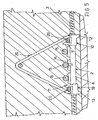
- the clamping device or element for clamping iron trestles or struts to be arranged in concrete floor slabs and walls which has been generally indicated by the reference number 1, comprises a plurality of blocks 2 which are clamped to a cross rod element or rebar 3.
- rod elements or rebars having a width of 118 cm to be used for making slabs of 120 cm, two side blocks and a central block would be provided.
- the block 2 comprises an elongated central body 4 coating the rebar 3 and which, at its end portions, is coupled to coupling or latching bodies 10 which, on a side thereof, comprise a plurality of foot elements 11, including respective tooth pattern, defining housing seats which are arranged substantially perpendicular to the rebar 3.
- a plurality of bearing feet 12 for bearing on the caisson while holding the rebar 3 in a raised condition.
- a plurality of seats are arranged for housing therein longitudinal iron elements 15, said seats comprising respective recesses 14 made in a single body with the central body 4.
- a set number of cross rod elements or rebars 3 are preliminarily arranged in the caisson, each said rebar having three blocks 2 bearing by their feet 12 on the caisson bottom.
- the trestles or struts 20 are engaged, in particular by coupling the first base iron element 20A in the seats defined by said feet 11 and laterally arranged, as schematically shown, in figure 3 .
- the longitudinal rod elements or rebars 15 are located, to be properly arranged on the recesses 14 and then, by a rotary operation, the second base iron element 20B is coupled in the latching body 10, while locking the trestle or strut 20 which will be thus restrained by a stable coupling of the base iron elements 20A and 20B.
- the above disclosed toothed feet 11 will provide a plurality of seats allowing to use trestles or struts having widths within a given width range.
- the clamping devices or elements, formed by the block 2 allows to hold in a raised condition the trestles or struts with respect to the casting bench, thereby allowing the concrete material to fully encompass and cover the two iron elements arranged at the bottom of the trestle.
- said trestles or struts are held in a spaced condition from one another at accurate and even distances.
- the invention provides a clamping device or element for clamping iron trestles or struts to be arranged in concrete floors or walls, thereby providing an optimum location of said trestles, while simplifying all the casting operations and providing a high quality end product.
Landscapes
- Engineering & Computer Science (AREA)
- Architecture (AREA)
- Civil Engineering (AREA)
- Structural Engineering (AREA)
- Mechanical Engineering (AREA)
- Reinforcement Elements For Buildings (AREA)
- Clamps And Clips (AREA)
- Joining Of Building Structures In Genera (AREA)
- Panels For Use In Building Construction (AREA)
Claims (6)
- Klemmvorrichtung (1) zum Klemmen von Bewehrungskörben oder Streben (20) zur Anordnung in Betonbodenplatten oder -wänden, wobei die Klemmvorrichtung (1) zumindest einen Block (2) umfasst, wobei der Block (2) mehrere Klinkenkörper (10) definiert, die abnehmbar an die Basiseisenelemente (20A, 20B) der Bewehrungskörbe (20) gekuppelt sind, wobei auf dem Block (2) zumindest ein Sitz zum Unterbringen von zumindest einem längs verlaufenden Stangenelement (15) vorgesehen ist, dadurch gekennzeichnet, dass der Block (2) zur starren Zuordnung zu einem Querbewehrungsstab (3) gestaltet ist.
- Klemmvorrichtung (1) nach dem vorhergehenden Anspruch, dadurch gekennzeichnet, dass ein zentraler Block (2) zur Anordnung auf jedem Querbewehrungsstab (3) gestaltet ist und zwei weitere Blöcke zur Anordnung an Endabschnitten des Querbewehrungsstabs (3) gestaltet sind.
- Klemmvorrichtung (1) nach Anspruch 1, dadurch gekennzeichnet, dass der Block (2) einen gestreckten zentralen Körper (4) umfasst, der die Klinkenkörper (10) miteinander verkuppelt, die an den Enden des Blocks (2) angeordnet sind.
- Klemmvorrichtung (1) nach Anspruch 1, dadurch gekennzeichnet, dass die Klinkenkörper (10) auf einer Oberseite davon mehrere gezahnte Fußelemente (11) zum Definieren von entsprechenden Kupplungssitzen für die Bewehrungskorbbasiseisenelemente (20A, 20B) definieren, die im Wesentlichen senkrecht zu dem Querbewehrungsstab (3) angeordnet sind, wobei die Klinkenkörper (10) an unteren Endabschnitten davon mehrere Lagerfüße (12) zum Vorsehen einer eingestellten Beabstandung von der Unterseite eines Senkkastens definieren.
- Klemmvorrichtung (1) nach Anspruch 1, dadurch gekennzeichnet, dass der Block (2) mehrere Aussparungen (14) umfasst, die mehrere entsprechende Unterbringungssitze zum Unterbringen von längs verlaufenden Stangenelementen (15) definieren.
- Verfahren zum Klemmen von Bewehrungskören oder Streben (20), dadurch gekennzeichnet, dass ein Basiseisenelement (20A) zunächst in einen Klinkenkörper (10) der Klemmvorrichtung nach Anspruch 1 geklemmt wird und, nachdem längs verlaufende Stangenelemente (15) in den Sitzen in Eingriff gebracht wurden, das andere Basiseisenelement (20B) in den anderen Klinkenkörper (10) gekuppelt wird.
Applications Claiming Priority (1)
| Application Number | Priority Date | Filing Date | Title |
|---|---|---|---|
| IT000221U ITMI20050221U1 (it) | 2005-06-17 | 2005-06-17 | Elemento per il fissaggio dei tralicci in ferro da inserire nelle lastre di solaio o dei muri in calcestruzzo |
Publications (3)
| Publication Number | Publication Date |
|---|---|
| EP1734201A2 EP1734201A2 (de) | 2006-12-20 |
| EP1734201A3 EP1734201A3 (de) | 2007-11-07 |
| EP1734201B1 true EP1734201B1 (de) | 2008-12-10 |
Family
ID=38519645
Family Applications (1)
| Application Number | Title | Priority Date | Filing Date |
|---|---|---|---|
| EP05023334A Expired - Lifetime EP1734201B1 (de) | 2005-06-17 | 2005-10-26 | Vorrichtung zum Klemmen von Bewehrungskörben oder Streben zur Anordnung in Betonbodenplatten oder -wänden |
Country Status (4)
| Country | Link |
|---|---|
| EP (1) | EP1734201B1 (de) |
| AT (1) | ATE417165T1 (de) |
| DE (1) | DE602005011592D1 (de) |
| IT (1) | ITMI20050221U1 (de) |
Cited By (1)
| Publication number | Priority date | Publication date | Assignee | Title |
|---|---|---|---|---|
| FR3127772A1 (fr) * | 2021-10-04 | 2023-04-07 | Isoltop | Procédé de fabrication d’une poutrelle et son installation. |
Families Citing this family (4)
| Publication number | Priority date | Publication date | Assignee | Title |
|---|---|---|---|---|
| ITRM20110287A1 (it) * | 2011-06-09 | 2012-12-10 | Giovanni Cenci | "metodo per la costruzione di solaio a lastra con fondello in legno e mezzi per la sua attuazione" |
| AU2014224166B2 (en) * | 2013-09-15 | 2018-10-11 | Bfre Pty Ltd As Trustee | Dual Mesh Level Reinforcement Bar Chair Assembly |
| EP2975189B1 (de) * | 2014-07-17 | 2022-07-27 | Sa Baufer V.F. | System zum verlegen von stäben, insbesondere zur herstellung von bewehrten betonkonstruktionen |
| CN109944392A (zh) * | 2019-03-25 | 2019-06-28 | 广东蕉岭建筑工程集团有限公司 | 一种钢筋分离器、混凝土结构及其施工方法 |
Family Cites Families (9)
| Publication number | Priority date | Publication date | Assignee | Title |
|---|---|---|---|---|
| AT328153B (de) * | 1972-11-27 | 1976-03-10 | Rheinbau Gmbh | Vorrichtung zur lagesicherung von bewehrungsstaben |
| DE2434851A1 (de) * | 1974-07-19 | 1976-02-05 | Rudolf Seifert | Abstandhalter fuer in betonbauteile einzubettende bewehrungen |
| DE2526370A1 (de) * | 1975-06-11 | 1976-12-23 | Karl Sobiella | Befestigungsvorrichtung fuer armierungseisen in betonverschalungen |
| AU504581B2 (en) * | 1976-02-25 | 1979-10-18 | Dobson Park Industries Limited | Mounting arrangement for tools |
| FR2419372A1 (fr) * | 1978-03-08 | 1979-10-05 | Maibach Henri | Agrafe pour treillis de poutrelle de construction, notamment de plancher ou de toit |
| DE3410484A1 (de) * | 1983-05-20 | 1985-10-03 | Bernhard 7613 Hausach Künstle | Deckenelement |
| DE3318431C2 (de) * | 1983-05-20 | 1985-12-12 | Bernhard 7613 Hausach Künstle | Deckenelement |
| DE9010331U1 (de) * | 1989-07-11 | 1990-09-20 | Bucher, Franz, Dipl.-Ing., Innsbruck | Einrichtung zur Festlegung zumindest eines Bewehrungsstabes |
| ITCR20020015A1 (it) * | 2002-09-11 | 2004-03-12 | Ezio Ferrari | Elemento metallico o in altro materiale per l'esatto |
-
2005
- 2005-06-17 IT IT000221U patent/ITMI20050221U1/it unknown
- 2005-10-26 EP EP05023334A patent/EP1734201B1/de not_active Expired - Lifetime
- 2005-10-26 AT AT05023334T patent/ATE417165T1/de not_active IP Right Cessation
- 2005-10-26 DE DE602005011592T patent/DE602005011592D1/de not_active Expired - Fee Related
Cited By (1)
| Publication number | Priority date | Publication date | Assignee | Title |
|---|---|---|---|---|
| FR3127772A1 (fr) * | 2021-10-04 | 2023-04-07 | Isoltop | Procédé de fabrication d’une poutrelle et son installation. |
Also Published As
| Publication number | Publication date |
|---|---|
| DE602005011592D1 (de) | 2009-01-22 |
| EP1734201A3 (de) | 2007-11-07 |
| ATE417165T1 (de) | 2008-12-15 |
| ITMI20050221U1 (it) | 2006-12-18 |
| EP1734201A2 (de) | 2006-12-20 |
Similar Documents
| Publication | Publication Date | Title |
|---|---|---|
| US9988775B1 (en) | Concrete i-beam for bridge construction | |
| KR100428285B1 (ko) | 미장용 레벨봉 | |
| US5660020A (en) | Method of construction using pre-cast floor units | |
| US4378203A (en) | Concrete mould and method of moulding concrete panels | |
| CN103669868B (zh) | 超长混凝土楼面结构的递推流水施工方法 | |
| EP0825307B1 (de) | Flügelförmiges Deckenelement aus Beton | |
| KR101211332B1 (ko) | Psc 거더와 프리캐스트 바닥판 연결 구조 | |
| US4522367A (en) | Matrix array for manufacturing concrete sleeper blocks | |
| EP1734201A2 (de) | Vorrichtung zum Klemmen von Bewehrungskörben oder Streben zur Anordnung in Betonbodenplatten oder -wänden | |
| US3938922A (en) | Means for forming a prestressed slab including collapsible bulkheads | |
| EP2657423B1 (de) | Betonplatte | |
| US20090000242A1 (en) | Wall forming apparatus and methods | |
| CN112218993A (zh) | 加强间隔件 | |
| US5029804A (en) | In situ brick or block making formwork | |
| CN220014500U (zh) | 混凝土楼板板厚控制装置 | |
| US6869553B1 (en) | Method for forming a precast brick riser | |
| US10550573B2 (en) | Reinforcing bar positioner and method | |
| US20060272268A1 (en) | Fireproof precast element with securement structure | |
| US4693046A (en) | Method of constructing floor for buildings or similar structures | |
| US6230447B1 (en) | Lifting anchor for prefabricated concrete panels | |
| US10697178B2 (en) | Reinforcing bar positioner and method | |
| US1520878A (en) | Method of forming reenforced cementitious slabs | |
| JP2003171994A (ja) | ボイドスラブとその構築方法 | |
| JPH06316939A (ja) | 建築工事用位置決め治具及びこれを用いた建築工法 | |
| KR0134427Y1 (ko) | 이탈 및 부상방지용 스페이서 |
Legal Events
| Date | Code | Title | Description |
|---|---|---|---|
| PUAI | Public reference made under article 153(3) epc to a published international application that has entered the european phase |
Free format text: ORIGINAL CODE: 0009012 |
|
| AK | Designated contracting states |
Kind code of ref document: A2 Designated state(s): AT BE BG CH CY CZ DE DK EE ES FI FR GB GR HU IE IS IT LI LT LU LV MC NL PL PT RO SE SI SK TR |
|
| AX | Request for extension of the european patent |
Extension state: AL BA HR MK YU |
|
| PUAL | Search report despatched |
Free format text: ORIGINAL CODE: 0009013 |
|
| AK | Designated contracting states |
Kind code of ref document: A3 Designated state(s): AT BE BG CH CY CZ DE DK EE ES FI FR GB GR HU IE IS IT LI LT LU LV MC NL PL PT RO SE SI SK TR |
|
| AX | Request for extension of the european patent |
Extension state: AL BA HR MK YU |
|
| 17P | Request for examination filed |
Effective date: 20080507 |
|
| GRAP | Despatch of communication of intention to grant a patent |
Free format text: ORIGINAL CODE: EPIDOSNIGR1 |
|
| AKX | Designation fees paid |
Designated state(s): AT BE BG CH CY CZ DE DK EE ES FI FR GB GR HU IE IS IT LI LT LU LV MC NL PL PT RO SE SI SK TR |
|
| GRAS | Grant fee paid |
Free format text: ORIGINAL CODE: EPIDOSNIGR3 |
|
| GRAS | Grant fee paid |
Free format text: ORIGINAL CODE: EPIDOSNIGR3 |
|
| GRAA | (expected) grant |
Free format text: ORIGINAL CODE: 0009210 |
|
| AK | Designated contracting states |
Kind code of ref document: B1 Designated state(s): AT BE BG CH CY CZ DE DK EE ES FI FR GB GR HU IE IS IT LI LT LU LV MC NL PL PT RO SE SI SK TR |
|
| REG | Reference to a national code |
Ref country code: GB Ref legal event code: FG4D |
|
| REG | Reference to a national code |
Ref country code: CH Ref legal event code: EP |
|
| REG | Reference to a national code |
Ref country code: IE Ref legal event code: FG4D |
|
| REF | Corresponds to: |
Ref document number: 602005011592 Country of ref document: DE Date of ref document: 20090122 Kind code of ref document: P |
|
| REG | Reference to a national code |
Ref country code: RO Ref legal event code: EPE |
|
| REG | Reference to a national code |
Ref country code: CH Ref legal event code: NV Representative=s name: BOVARD AG PATENTANWAELTE |
|
| PG25 | Lapsed in a contracting state [announced via postgrant information from national office to epo] |
Ref country code: LT Free format text: LAPSE BECAUSE OF FAILURE TO SUBMIT A TRANSLATION OF THE DESCRIPTION OR TO PAY THE FEE WITHIN THE PRESCRIBED TIME-LIMIT Effective date: 20081210 |
|
| PG25 | Lapsed in a contracting state [announced via postgrant information from national office to epo] |
Ref country code: LV Free format text: LAPSE BECAUSE OF FAILURE TO SUBMIT A TRANSLATION OF THE DESCRIPTION OR TO PAY THE FEE WITHIN THE PRESCRIBED TIME-LIMIT Effective date: 20081210 Ref country code: FI Free format text: LAPSE BECAUSE OF FAILURE TO SUBMIT A TRANSLATION OF THE DESCRIPTION OR TO PAY THE FEE WITHIN THE PRESCRIBED TIME-LIMIT Effective date: 20081210 Ref country code: PL Free format text: LAPSE BECAUSE OF FAILURE TO SUBMIT A TRANSLATION OF THE DESCRIPTION OR TO PAY THE FEE WITHIN THE PRESCRIBED TIME-LIMIT Effective date: 20081210 Ref country code: NL Free format text: LAPSE BECAUSE OF FAILURE TO SUBMIT A TRANSLATION OF THE DESCRIPTION OR TO PAY THE FEE WITHIN THE PRESCRIBED TIME-LIMIT Effective date: 20081210 Ref country code: SI Free format text: LAPSE BECAUSE OF FAILURE TO SUBMIT A TRANSLATION OF THE DESCRIPTION OR TO PAY THE FEE WITHIN THE PRESCRIBED TIME-LIMIT Effective date: 20081210 |
|
| PGFP | Annual fee paid to national office [announced via postgrant information from national office to epo] |
Ref country code: RO Payment date: 20090227 Year of fee payment: 5 |
|
| NLV1 | Nl: lapsed or annulled due to failure to fulfill the requirements of art. 29p and 29m of the patents act | ||
| PG25 | Lapsed in a contracting state [announced via postgrant information from national office to epo] |
Ref country code: BE Free format text: LAPSE BECAUSE OF FAILURE TO SUBMIT A TRANSLATION OF THE DESCRIPTION OR TO PAY THE FEE WITHIN THE PRESCRIBED TIME-LIMIT Effective date: 20081210 Ref country code: EE Free format text: LAPSE BECAUSE OF FAILURE TO SUBMIT A TRANSLATION OF THE DESCRIPTION OR TO PAY THE FEE WITHIN THE PRESCRIBED TIME-LIMIT Effective date: 20081210 Ref country code: ES Free format text: LAPSE BECAUSE OF FAILURE TO SUBMIT A TRANSLATION OF THE DESCRIPTION OR TO PAY THE FEE WITHIN THE PRESCRIBED TIME-LIMIT Effective date: 20090321 Ref country code: BG Free format text: LAPSE BECAUSE OF FAILURE TO SUBMIT A TRANSLATION OF THE DESCRIPTION OR TO PAY THE FEE WITHIN THE PRESCRIBED TIME-LIMIT Effective date: 20090310 |
|
| PG25 | Lapsed in a contracting state [announced via postgrant information from national office to epo] |
Ref country code: AT Free format text: LAPSE BECAUSE OF FAILURE TO SUBMIT A TRANSLATION OF THE DESCRIPTION OR TO PAY THE FEE WITHIN THE PRESCRIBED TIME-LIMIT Effective date: 20081210 Ref country code: CZ Free format text: LAPSE BECAUSE OF FAILURE TO SUBMIT A TRANSLATION OF THE DESCRIPTION OR TO PAY THE FEE WITHIN THE PRESCRIBED TIME-LIMIT Effective date: 20081210 Ref country code: PT Free format text: LAPSE BECAUSE OF FAILURE TO SUBMIT A TRANSLATION OF THE DESCRIPTION OR TO PAY THE FEE WITHIN THE PRESCRIBED TIME-LIMIT Effective date: 20090511 Ref country code: SE Free format text: LAPSE BECAUSE OF FAILURE TO SUBMIT A TRANSLATION OF THE DESCRIPTION OR TO PAY THE FEE WITHIN THE PRESCRIBED TIME-LIMIT Effective date: 20090310 Ref country code: IS Free format text: LAPSE BECAUSE OF FAILURE TO SUBMIT A TRANSLATION OF THE DESCRIPTION OR TO PAY THE FEE WITHIN THE PRESCRIBED TIME-LIMIT Effective date: 20090410 |
|
| PG25 | Lapsed in a contracting state [announced via postgrant information from national office to epo] |
Ref country code: SK Free format text: LAPSE BECAUSE OF FAILURE TO SUBMIT A TRANSLATION OF THE DESCRIPTION OR TO PAY THE FEE WITHIN THE PRESCRIBED TIME-LIMIT Effective date: 20081210 |
|
| PLBE | No opposition filed within time limit |
Free format text: ORIGINAL CODE: 0009261 |
|
| STAA | Information on the status of an ep patent application or granted ep patent |
Free format text: STATUS: NO OPPOSITION FILED WITHIN TIME LIMIT |
|
| PG25 | Lapsed in a contracting state [announced via postgrant information from national office to epo] |
Ref country code: DK Free format text: LAPSE BECAUSE OF FAILURE TO SUBMIT A TRANSLATION OF THE DESCRIPTION OR TO PAY THE FEE WITHIN THE PRESCRIBED TIME-LIMIT Effective date: 20081210 |
|
| 26N | No opposition filed |
Effective date: 20090911 |
|
| PGFP | Annual fee paid to national office [announced via postgrant information from national office to epo] |
Ref country code: CH Payment date: 20091029 Year of fee payment: 5 |
|
| PG25 | Lapsed in a contracting state [announced via postgrant information from national office to epo] |
Ref country code: MC Free format text: LAPSE BECAUSE OF NON-PAYMENT OF DUE FEES Effective date: 20091031 |
|
| REG | Reference to a national code |
Ref country code: IE Ref legal event code: MM4A |
|
| REG | Reference to a national code |
Ref country code: FR Ref legal event code: ST Effective date: 20100630 |
|
| PG25 | Lapsed in a contracting state [announced via postgrant information from national office to epo] |
Ref country code: FR Free format text: LAPSE BECAUSE OF NON-PAYMENT OF DUE FEES Effective date: 20091102 Ref country code: DE Free format text: LAPSE BECAUSE OF NON-PAYMENT OF DUE FEES Effective date: 20100501 |
|
| PG25 | Lapsed in a contracting state [announced via postgrant information from national office to epo] |
Ref country code: GR Free format text: LAPSE BECAUSE OF FAILURE TO SUBMIT A TRANSLATION OF THE DESCRIPTION OR TO PAY THE FEE WITHIN THE PRESCRIBED TIME-LIMIT Effective date: 20090311 Ref country code: IE Free format text: LAPSE BECAUSE OF NON-PAYMENT OF DUE FEES Effective date: 20091026 |
|
| PG25 | Lapsed in a contracting state [announced via postgrant information from national office to epo] |
Ref country code: GB Free format text: LAPSE BECAUSE OF NON-PAYMENT OF DUE FEES Effective date: 20091026 |
|
| PGFP | Annual fee paid to national office [announced via postgrant information from national office to epo] |
Ref country code: IT Payment date: 20101026 Year of fee payment: 6 |
|
| REG | Reference to a national code |
Ref country code: CH Ref legal event code: PFA Owner name: FUMAGALLI EDILIZIA INDUSTRIALIZZATA S.P.A. Free format text: FUMAGALLI EDILIZIA INDUSTRIALIZZATA S.P.A.#VIA ROMA 23#23892 BULCIAGO (LC) (IT) -TRANSFER TO- FUMAGALLI EDILIZIA INDUSTRIALIZZATA S.P.A.#VIA ROMA 23#23892 BULCIAGO (LC) (IT) |
|
| PG25 | Lapsed in a contracting state [announced via postgrant information from national office to epo] |
Ref country code: LU Free format text: LAPSE BECAUSE OF NON-PAYMENT OF DUE FEES Effective date: 20091026 |
|
| REG | Reference to a national code |
Ref country code: CH Ref legal event code: PL |
|
| PG25 | Lapsed in a contracting state [announced via postgrant information from national office to epo] |
Ref country code: HU Free format text: LAPSE BECAUSE OF FAILURE TO SUBMIT A TRANSLATION OF THE DESCRIPTION OR TO PAY THE FEE WITHIN THE PRESCRIBED TIME-LIMIT Effective date: 20090611 |
|
| PG25 | Lapsed in a contracting state [announced via postgrant information from national office to epo] |
Ref country code: LI Free format text: LAPSE BECAUSE OF NON-PAYMENT OF DUE FEES Effective date: 20101031 Ref country code: CH Free format text: LAPSE BECAUSE OF NON-PAYMENT OF DUE FEES Effective date: 20101031 |
|
| PG25 | Lapsed in a contracting state [announced via postgrant information from national office to epo] |
Ref country code: TR Free format text: LAPSE BECAUSE OF FAILURE TO SUBMIT A TRANSLATION OF THE DESCRIPTION OR TO PAY THE FEE WITHIN THE PRESCRIBED TIME-LIMIT Effective date: 20081210 Ref country code: RO Free format text: LAPSE BECAUSE OF NON-PAYMENT OF DUE FEES Effective date: 20101026 |
|
| PG25 | Lapsed in a contracting state [announced via postgrant information from national office to epo] |
Ref country code: CY Free format text: LAPSE BECAUSE OF FAILURE TO SUBMIT A TRANSLATION OF THE DESCRIPTION OR TO PAY THE FEE WITHIN THE PRESCRIBED TIME-LIMIT Effective date: 20081210 |
|
| PG25 | Lapsed in a contracting state [announced via postgrant information from national office to epo] |
Ref country code: IT Free format text: LAPSE BECAUSE OF NON-PAYMENT OF DUE FEES Effective date: 20111026 |