EP1734288A2 - Différentiel pour véhicule - Google Patents
Différentiel pour véhicule Download PDFInfo
- Publication number
- EP1734288A2 EP1734288A2 EP06012251A EP06012251A EP1734288A2 EP 1734288 A2 EP1734288 A2 EP 1734288A2 EP 06012251 A EP06012251 A EP 06012251A EP 06012251 A EP06012251 A EP 06012251A EP 1734288 A2 EP1734288 A2 EP 1734288A2
- Authority
- EP
- European Patent Office
- Prior art keywords
- ring
- pinion gear
- pinion
- differential case
- gears
- Prior art date
- Legal status (The legal status is an assumption and is not a legal conclusion. Google has not performed a legal analysis and makes no representation as to the accuracy of the status listed.)
- Withdrawn
Links
- 230000002093 peripheral effect Effects 0.000 claims abstract description 10
- 238000010276 construction Methods 0.000 description 4
- 238000005299 abrasion Methods 0.000 description 3
- 230000032683 aging Effects 0.000 description 3
- 230000009699 differential effect Effects 0.000 description 3
- 230000015556 catabolic process Effects 0.000 description 2
- 238000006731 degradation reaction Methods 0.000 description 2
- 238000006073 displacement reaction Methods 0.000 description 2
- 230000017525 heat dissipation Effects 0.000 description 2
- 238000003754 machining Methods 0.000 description 2
- 238000000034 method Methods 0.000 description 2
- 230000005540 biological transmission Effects 0.000 description 1
- 230000000694 effects Effects 0.000 description 1
Images


Classifications
-
- F—MECHANICAL ENGINEERING; LIGHTING; HEATING; WEAPONS; BLASTING
- F16—ENGINEERING ELEMENTS AND UNITS; GENERAL MEASURES FOR PRODUCING AND MAINTAINING EFFECTIVE FUNCTIONING OF MACHINES OR INSTALLATIONS; THERMAL INSULATION IN GENERAL
- F16H—GEARING
- F16H48/00—Differential gearings
- F16H48/06—Differential gearings with gears having orbital motion
- F16H48/08—Differential gearings with gears having orbital motion comprising bevel gears
- F16H2048/082—Differential gearings with gears having orbital motion comprising bevel gears characterised by the arrangement of output shafts
-
- F—MECHANICAL ENGINEERING; LIGHTING; HEATING; WEAPONS; BLASTING
- F16—ENGINEERING ELEMENTS AND UNITS; GENERAL MEASURES FOR PRODUCING AND MAINTAINING EFFECTIVE FUNCTIONING OF MACHINES OR INSTALLATIONS; THERMAL INSULATION IN GENERAL
- F16H—GEARING
- F16H48/00—Differential gearings
- F16H48/06—Differential gearings with gears having orbital motion
- F16H48/08—Differential gearings with gears having orbital motion comprising bevel gears
- F16H2048/085—Differential gearings with gears having orbital motion comprising bevel gears characterised by shafts or gear carriers for orbital gears
-
- F—MECHANICAL ENGINEERING; LIGHTING; HEATING; WEAPONS; BLASTING
- F16—ENGINEERING ELEMENTS AND UNITS; GENERAL MEASURES FOR PRODUCING AND MAINTAINING EFFECTIVE FUNCTIONING OF MACHINES OR INSTALLATIONS; THERMAL INSULATION IN GENERAL
- F16H—GEARING
- F16H48/00—Differential gearings
- F16H48/06—Differential gearings with gears having orbital motion
- F16H48/08—Differential gearings with gears having orbital motion comprising bevel gears
- F16H2048/087—Differential gearings with gears having orbital motion comprising bevel gears characterised by the pinion gears, e.g. their type or arrangement
-
- F—MECHANICAL ENGINEERING; LIGHTING; HEATING; WEAPONS; BLASTING
- F16—ENGINEERING ELEMENTS AND UNITS; GENERAL MEASURES FOR PRODUCING AND MAINTAINING EFFECTIVE FUNCTIONING OF MACHINES OR INSTALLATIONS; THERMAL INSULATION IN GENERAL
- F16H—GEARING
- F16H48/00—Differential gearings
- F16H48/38—Constructional details
- F16H2048/382—Methods for manufacturing differential gearings
-
- F—MECHANICAL ENGINEERING; LIGHTING; HEATING; WEAPONS; BLASTING
- F16—ENGINEERING ELEMENTS AND UNITS; GENERAL MEASURES FOR PRODUCING AND MAINTAINING EFFECTIVE FUNCTIONING OF MACHINES OR INSTALLATIONS; THERMAL INSULATION IN GENERAL
- F16H—GEARING
- F16H48/00—Differential gearings
- F16H48/38—Constructional details
- F16H2048/387—Shields or washers
Definitions
- the present invention relates to a differential gearing for vehicle comprising a plurality of pinion gears which are rotatably held within a differential case and a pair of side gears disposed in meshing engagement with the pinion gears and connected to left and right axles, respectively, and in particular, to a differential gearing for vehicle in which a removal of the pinion gears is prevented by a ring which is fitted around the differential case.
- a conventional differential gearing for vehicle is known as having a construction as disclosed in Japanese Utility Model No. 2520728 , for example.
- This differential gearing for vehicle of the prior art will be briefly described with reference to Fig. 7. It is to be noted that reference characters for the conventional construction shown in Fig. 7 will be indicated in parentheses in this specification.
- Formed in a differential case (12) are a pinion gear receiving opening (14) and an axle receiving opening (16) which extend orthogonally to each other.
- Left and right side gears (20L, 20R) are disposed within the differential case (12) so as to be axially movable therein and are splined to left and right axles (22L, 22R).
- Thrust washers (24) of a smaller diameter than the side gears (20L, 20R) are disposed between the back surfaces (20La, 20Ra) of the left and right side gears (20L, 20R) and the internal surface of the differential case (12).
- a pinion gear (26) is disposed within the differential case (12) and rotatably supported therein. These pinion gears (26) are in meshing engagement with the left and right side gears (20L, 20R).
- a pinion gear holding plate (28) is fitted over the external diameter of the pinion gear (26), which is prevented from being removed from the differential case (12) by a snap ring (30) which is fitted into a groove (12a) in the differential case (12).
- an end of the pinion gear (26) which is disposed toward the outer periphery is planar, and the pinion gear (26) may be displaced in position when a torque is transmitted to the differential case (12), and there is a likelihood that satisfactory meshing engagement with the side gears (20L, 20R) cannot be achieved. Because a pinion gear holding plate (28) must be fitted over the external diameter of each of the plurality of pinion gears (26) and must be locked against withdrawal by the snap ring (30), there remains a problem that the assembly is cumbersome.
- a differential gearing for vehicle comprising a plurality of pinion gears rotatably held in a pinion gear receiving opening formed in a differential case, and a pair of side gears disposed in right-angle meshing engagement with the pinion gears and connected to two axles which are coaxially disposed and in which a ring is fitted around the outer periphery of each pinion gear in coaxial relationship with the differential case and includes an inner peripheral surface in which a spherical recess centered about a point of intersection between an axis of rotation of the side gear and an axis of rotation of the pinion gear is formed while an end of the pinion gear which is disposed toward the outer periphery is formed with a spherical projection having a similar curvature as the recess in the inner peripheral surface of the ring.
- the invention defined in Claim 2 is characterized in that the ring is formed with an axial notch at a location which corresponds to the pinion gear receiving opening. By axially sliding the notch to be aligned with the location of the pinion gear after the pinion gear has been inserted into the pinion gear receiving opening, the ring is fitted around the outer periphery of the pinion gear.
- the assembly is improved.
- the location of the notch is aligned with the location of the external surface of the pinion gear, the heat dissipation from the external surface of the pinion gear and the sliding surface of the ring is improved, thus improving the seizure resistance.
- the invention defined in Claim 3 is characterized in that after the ring is fitted around the outer periphery of the pinion gears, the ring is rotated relative to the differential case circumferentially and is locked against rotation with respect to the differential case.
- an area of sliding contact between the spherical external surface of the pinion gear and the pinion gear sliding surface can be increased than for the arrangement of Claim 2, permitting the abrasion to be reduced and allowing an aging change in a differential action limiting force to be suppressed.
- the invention defined in Claim 4 is characterized in that the ring is formed with a diametrical opening at a location which corresponds to the pinion gear receiving opening.
- the pinion gear is inserted into the pinion gear receiving opening under a condition that the ring is fitted around the differential case so that the diametrical opening is aligned with the pinion gear receiving opening, and the ring is then circumferentially rotated relative to the differential case and is locked against rotation relative to the differential case.
- the pinion gear is inserted after the ring is fitted around the differential case, facilitating the assembly.
- a differential gearing for vehicle 1 includes a differential case 2 which is of a three-piece construction.
- a disk-shaped, first case 2A disposed to the left as viewed in Fig. 1, a cylindrical, second case 2B of a smaller diameter which is located to the right and a substantially cylindrical, third case 2C disposed therebetween are disposed in abutment against each other and are secured together as by bolts.
- the differential gearing for vehicle 1 comprises two pinion gears 4A (one being not shown) which are rotatably held within the differential case 2, and a pair of left and right side gears 6L, 6R received within the differential case 2 and disposed to be in meshing engagement with the both pinion gears 4A simultaneously and connected to left and right axles (not shown) by splines 6La, 6Ra which are formed in their inner peripheral surfaces.
- the differential case 2 is formed with axle receiving openings 10L, 10R extending through the axis thereof and in which left and right axles are passed, and pinion gear receiving openings 12A, 12B extending in a direction orthogonal to the axle receiving openings 10L, 10R and facing said internal space.
- the differential case 2 is formed with a flange 2a which is located in a plane which is orthogonal to an axis of rotation O1 of the differential gearing 1, and a torque from a drive pinion is input through a ring gear (not shown) which is mounted on the flange 2a.
- the pinion gear 4A includes a gear meshing portion 4Aa which meshes with the side gears 6L, 6R and which is inserted into the internal space within the differential case 2 through the pinion gear receiving opening 12A.
- a pinion gear receiving opening 12B is formed on the opposite side of the differential case 2 so as to oppose the pinion gear receiving opening 12A, and while not shown in Fig. 1, the pinion gear 4B (see Fig. 2) is rotatably held in the pinion gear receiving opening 12B.
- the pinion gears 4A, 4B include a carried portion 4Ab disposed toward the outer end which is rotatably carried by the inner peripheral surfaces (pinion gear holding surfaces) of the pinion gear receiving openings 12A, 12B. As indicated in the lower portion of Fig.
- the internal surface of the pinion gear receiving openings 12A, 12B extends inward into the differential case 2 (the extension being indicated by character 12Bb) and the pinion gear holding surfaces (inner peripheral surfaces 12Aa, 12Ba of the pinion gear receiving openings 12A, 12B and the extensions 12Bb) support the pinion gears 4A, 4B including the carried portions 4Ab, 4Bb and part of the meshing portions 4Aa, 4Ba over an axially elongate extent of the pinion gears 4A, 4B. In this manner, a tilting of the pinion gears 4A, 4B during the transmission of a torque is prevented. It is to be noted that the pinion gears 4A, 4B do not include pinion pins which are usually fitted to extend through the axes thereof.
- the side gears 6L, 6R which are received within the internal space of the differential case 2 for meshing engagement with the pinion gears 4A, 4B represent bevel gears of a larger size as compared with the pinion gears 4A, 4B, and have a number of teeth which is equal to or greater than 2.5 times the number of teeth of the pinion gears 4A, 4B, for example.
- Thrust washers 16L, 16R are interposed between flat surfaces on the rear side of the both side gears 6L, 6R and the internal surface of the differential case 2. A withdrawal of the pinion gears 4A, 4B which are inserted into the pinion gear receiving openings 12A, 12B is prevented by a ring 18A which is fitted around the outer periphery of the pinion gears 4A, 4B.
- the ring 18A On its internal surface, the ring 18A includes a pinion gear sliding surface 18Aa, which is a spherical recess centered about a point of intersection between an axis of rotation of the side gears 6L, 6R and an axis of rotation of the pinion gears 4A, 4B, and thus these spherical surfaces are in sliding contact with spherical external surfaces 4Ac of the pinion gears 4A, 4B.
- the spherical external surface 4Ac has a curvature which is substantially equal to the curvature of the pinion gear sliding surface 18Aa.
- Fig. 2 is an illustration of the ring 18A which prevents the withdrawal of the pinion gears and its contact with the pinion gears 4A, 4B while the detail such as the tooth surfaces of the pinion gears 4A, 4B are omitted from illustration.
- the ring 18A is annular, having no notch or hiatus, and the pinion gear sliding surface 18Aa is circumferentially formed with two oil grooves 18Ab.
- the ring 18A is fitted around the outer periphery of the pinion gears 4A, 4B by axially sliding from one of directions of the axles of the differential case 2 (the right side as viewed in Fig.
- the ring 18A has an internal diameter at the opposite ends of the pinion sliding surface 18Aa which is less than the distance between the outer ends of the pinion gears 4A, 4B, and cannot be directly fitted around the outer periphery of the pinion gears 4A, 4B. For this reason, the ring 18A is heated to cause a thermal expansion, and after it is slid around the outer periphery of the pinion gears 4A, 4B, it is then cooled down to effect this fitting.
- the differential case 2 is constructed with three pieces 2A, 2B and 2C so as to permit an assembling from either side with an assembling procedure as mentioned below.
- the side gears 6L, 6R and the thrust washers 16L, 16R are assembled into the central, third case 2C from the both sides, and then the first case 2A and the second case 2B are secured to the opposite sides of the central third case 2C.
- the pinion gears 4A, 4B are then inserted through the pinion gear receiving openings 12A, 12B, and then the heated ring 18A is slid in one of the directions of the axles in the differential case 2 (refer an arrow A shown in Fig.
- the third case 2C which is centrally located in the differential case 2 is formed with a step 2Ca adjacent to the pinion gear receiving openings 12A, 12B, and the end face 18Ac of the ring 18A is brought into abutment against the step 2Ca, thus positioning the ring 18A which is fitted over the differential case 2.
- a torque from an engine is input to the differential case 2 through a drive pinion and a ring gear, both not shown, to cause it to rotate in either direction about the axis of rotation O1.
- the left and right side gears 6L, 6R are splined to the left and right axles (not shown) to transmit the torque thereto.
- the left wheel When a vehicle is turning, to the left, for example, the left wheel experiences a greater resistance as compared with a right wheel, or when one of the wheels slips because of a wrong road condition, for example, when the right wheel is trapped in a mire, the right wheel experiences a less resistance.
- the left axle and the side gear 6L which experience a greater resistance rotate at a slower speed than the rotation of the differential case 2, and since the pinion gears 4A, 4B received in the pinion gear receiving openings 12A, 12B in the differential case 2 are rotatably carried therein to allow a rotation about their own axes by being carried by the pinion gear holding surfaces (the inner peripheral surfaces of the pinion gear receiving openings 12A, 12B and the extensions), the right side gear 6R and the axle which experience a less resistance rotate at a faster speed than the rotation of the differential case 2.
- the pinion gears 4A, 4B rotate by the influence of the force which is input from the ring gear (not shown) to be urged against the sliding surface 18Aa of the ring 18A, developing a frictional resistance.
- This frictional force limits a differential rotation between the left and right side gears 6L, 6R, and also limit a differential rotation between the left and right axles which are splined to the left and right side gears 6L, 6R.
- the pinion gears 4A, 4B have spherical end faces 4Ac toward the outer periphery thereof, and a force which is developed in the axial direction of the pinion gears 4A, 4B by the meshing engagement with the side gears 6L, 6R and the centrifugal force produced by the rotation of the differential case 2 and acting upon the pinion gears 4A, 4B cause the spherical external surfaces 4Ac to be urged against the pinion gear sliding surface 18Aa of the ring 18A, thus developing a force which returns the pinion gears 4A, 4B to their original positions.
- the spherical external surface 4Ac has a curvature which is substantially equal to the curvature of the pinion gear sliding surface 18Aa, and accordingly, a sliding area between these surfaces can be increased to reduce the abrasion, whereby an aging change in the differential action limiting force can be reduced.
- the ring 18A is annular and is free from any notch and is fitted around the outer periphery of the pinion gears 4A, 4B by causing its thermal expansion.
- the ring 18A may be provided with a notch.
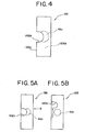
- a ring 18B is formed with a notch 18Bb in a manner corresponding to the position where the pinion gears 4A, 4B received within the differential case 2 assumes circumferentially.
- the notch 18Bb is formed at two locations which are symmetrically disposed by being 180° apart.
- the notch 18Bb is notched in the axial direction of the ring 18B from the end face 18Bc which is initially fitted (the left end face as viewed in Figs. 3 and 4) toward the pinion gear sliding surface 18Aa when the ring 18B which prevents the withdrawal of the pinion gear is fitted around the outer periphery of the differential case 2.
- the notch 18Bb is internally arcuate in configuration, and the end of the arc (deepest end) reaches substantially the center of a pinion gear sliding surface 18Ba (a portion shown in broken lines in Fig.
- the ring 18B which prevents the withdrawal of the pinion gears 4A, 4B is formed with the notch 18Bb in a manner corresponding to the location of each pinion gear 4A, 4B, thus allowing the ring 18B to be fitted around the differential case 2 after the side gears 6L, 6R have been inserted into the differential case 2 and then the pinion gears 4A, 4B have been secured in position for meshing engagement with the side gears 6L, 6R, thus improving the assembly.
- the location of the notch 18Bb in the ring 18B is aligned with the position of each pinion gear 4A when it is fitted around the outer periphery of the differential case 2 and then secured in position, and accordingly, the location of the notch 18Bb can be maintained aligned with the position of the external surface 4Ac of the pinion gear, improving the heat dissipation from the external surface 4Ac of the pinion gear 4A and the sliding portion 18Ba of the ring 18B and improving the seizure resistance.
- the location of the notch 18Bb formed in the ring 18B which prevents the withdrawal of the pinion gears 4A, 4B is aligned with the position of the pinion gears 4A, 4B carried within the differential case 2 when it is fitted and is then secured to the differential case 2.
- the ring 18B which prevents the withdrawal is fitted around the differential case 2 (refer arrow B) and then rotated (refer arrow C) to bring the location of the notch 18Bb offset from the position of the pinion gears 4A, 4B (the position of the external surface 4Ac on the pinion gear 4A).
- Figs. 6A to 6C is a view showing a ring 18C which prevents the withdrawal of a pinion gear in a differential gearing for vehicle 1 according to a fourth embodiment.
- the notch 18Bb is formed on the forward side when the ring 18B is fitted around the differential case 2.
- a circular opening 18Cd is formed in a manner corresponding to the positions of the pinion gears 4A, 4B which are disposed on a circumference of the differential case 2 and through which the pinion gears 4A, 4B can be passed.
- the pinion gears 4A, 4B are inserted.
- the ring 18C is fitted by aligning respective circular openings 18Cd formed therein in alignment with the positions of the pinion gear receiving openings 12A, 12B formed in the differential case 2 (refer arrow D).
- the ring 18C is rotated (refer arrow E).
- the ring 18B can be used in place which is reached by fitting it, but when the opening 18Cd is formed in the ring 18C, if it is left in place, the pinion gears 4A, 4B will be disengaged and withdrawn. Accordingly, it is necessary that the ring be rotated to have the circular opening 18Cd displaced from the position of the pinion gear 4A, 4B. To prevent the ring 18C from being rotated subsequently to return to the position of either pinion 4A, 4B, the ring 18C is locked against withdrawal and locked against rotation. In the present embodiment, the ring is locked against withdrawal and locked against rotation by folding a tab 18Ce which is formed on the end face of the ring 18C.
- the differential case 2 be formed with a corresponding groove.
- a pin or a screw may be inserted and secured in the end face of the differential case 2 which is located on the opposite side from the step 2Ca (refer Fig. 1).
- a snap ring may be fitted on the opposite end face from the step 2Ca, or the end face which is opposite from the step 2Ca may be caulked and secured.
Landscapes
- Engineering & Computer Science (AREA)
- General Engineering & Computer Science (AREA)
- Mechanical Engineering (AREA)
- Retarders (AREA)
- General Details Of Gearings (AREA)
Applications Claiming Priority (1)
| Application Number | Priority Date | Filing Date | Title |
|---|---|---|---|
| JP2005178579A JP2006349117A (ja) | 2005-06-17 | 2005-06-17 | 車両用差動歯車装置 |
Publications (2)
| Publication Number | Publication Date |
|---|---|
| EP1734288A2 true EP1734288A2 (fr) | 2006-12-20 |
| EP1734288A3 EP1734288A3 (fr) | 2008-01-23 |
Family
ID=36808163
Family Applications (1)
| Application Number | Title | Priority Date | Filing Date |
|---|---|---|---|
| EP06012251A Withdrawn EP1734288A3 (fr) | 2005-06-17 | 2006-06-14 | Différentiel pour véhicule |
Country Status (3)
| Country | Link |
|---|---|
| US (1) | US20060287155A1 (fr) |
| EP (1) | EP1734288A3 (fr) |
| JP (1) | JP2006349117A (fr) |
Cited By (7)
| Publication number | Priority date | Publication date | Assignee | Title |
|---|---|---|---|---|
| EP1777438A1 (fr) | 2005-10-21 | 2007-04-25 | Jtekt Corporation | Dispositif de transmission différentielle d'un véhicule, dispositif de transmission différentielle d'un véhicule combiné et boîtier du dispositif de transmission différentielle d'un véhicule |
| EP2055993A1 (fr) | 2007-11-02 | 2009-05-06 | Jtekt Corporation | Appareil différentiel de véhicule et son procédé d'assemblage |
| WO2010027413A3 (fr) * | 2008-09-04 | 2010-04-22 | Dana Heavy Vehicle Systems Group, Llc | Differentiel exempt de croisillon pour vehicule |
| EP2110582A4 (fr) * | 2007-02-02 | 2010-11-24 | Toyota Motor Co Ltd | Dispositif differentiel pour vehicule |
| CN105546082A (zh) * | 2014-10-22 | 2016-05-04 | 武藏精密工业株式会社 | 差动装置 |
| CN105546090A (zh) * | 2014-10-22 | 2016-05-04 | 武藏精密工业株式会社 | 差动装置 |
| US9534679B2 (en) * | 2015-06-04 | 2017-01-03 | Gm Global Technology Operations, Llc | Vehicle differential assembly |
Families Citing this family (6)
| Publication number | Priority date | Publication date | Assignee | Title |
|---|---|---|---|---|
| JP4400517B2 (ja) | 2004-07-09 | 2010-01-20 | 株式会社ジェイテクト | 車両用差動歯車装置 |
| JP4888151B2 (ja) * | 2006-08-28 | 2012-02-29 | 株式会社ジェイテクト | 車両用差動装置及びその組立方法 |
| DE102007021437A1 (de) * | 2007-05-08 | 2008-11-13 | ThyssenKrupp Präzisionsschmiede GmbH | Differential in Leichtbauweise für Kraftfahrzeuge |
| US20100151983A1 (en) * | 2008-12-11 | 2010-06-17 | Ziech James F | Spider-less vehicle differential |
| US9115785B1 (en) * | 2012-11-27 | 2015-08-25 | Radu Kramer | Compact drive mechanism with selective reverse power output |
| WO2024224592A1 (fr) * | 2023-04-28 | 2024-10-31 | 株式会社ジェイテクト | Dispositif différentiel |
Family Cites Families (9)
| Publication number | Priority date | Publication date | Assignee | Title |
|---|---|---|---|---|
| US1657091A (en) * | 1927-07-23 | 1928-01-24 | Timken Axle Co Detroit | Differential mechanism |
| SE440134B (sv) * | 1983-01-11 | 1985-07-15 | Volvo Ab | Differentialvexel |
| JP2520728Y2 (ja) * | 1991-05-30 | 1996-12-18 | 栃木富士産業株式会社 | 差動制限装置 |
| JP2776669B2 (ja) * | 1991-12-25 | 1998-07-16 | 日立建機株式会社 | フック過巻き防止装置 |
| US5718653A (en) * | 1993-08-02 | 1998-02-17 | Borg-Warner Automotive, Inc. | Differential assembly for transfer cases and vehicle drivelines |
| DE19621102C1 (de) * | 1996-05-24 | 1997-08-14 | Man Nutzfahrzeuge Ag | Zwischenachsdifferential für Kraftfahrzeuge |
| JPH11218211A (ja) * | 1998-01-30 | 1999-08-10 | Tochigi Fuji Ind Co Ltd | デファレンシャル装置 |
| US6699154B2 (en) * | 2002-01-31 | 2004-03-02 | Visteon Global Technologies, Inc. | Differential gear assembly |
| DE10310215A1 (de) * | 2003-03-08 | 2004-09-16 | Daimlerchrysler Ag | Umlaufräder-Getriebe in Kegelrad-Bauweise mit durch Schmiermittel versorgten Schmierstellen |
-
2005
- 2005-06-17 JP JP2005178579A patent/JP2006349117A/ja not_active Withdrawn
-
2006
- 2006-06-14 EP EP06012251A patent/EP1734288A3/fr not_active Withdrawn
- 2006-06-16 US US11/424,588 patent/US20060287155A1/en not_active Abandoned
Non-Patent Citations (1)
| Title |
|---|
| None |
Cited By (14)
| Publication number | Priority date | Publication date | Assignee | Title |
|---|---|---|---|---|
| EP1777438A1 (fr) | 2005-10-21 | 2007-04-25 | Jtekt Corporation | Dispositif de transmission différentielle d'un véhicule, dispositif de transmission différentielle d'un véhicule combiné et boîtier du dispositif de transmission différentielle d'un véhicule |
| US7749124B2 (en) | 2005-10-21 | 2010-07-06 | Jtekt Corporation | Vehicle differential gear device, vehicle combined differential gear device and vehicle differential case |
| US8591373B2 (en) | 2007-02-02 | 2013-11-26 | Toyota Jidosha Kabushiki Kaisha | Differential gear device for vehicle |
| CN101595329B (zh) * | 2007-02-02 | 2012-10-10 | 丰田自动车株式会社 | 车辆用差速装置 |
| EP2110582A4 (fr) * | 2007-02-02 | 2010-11-24 | Toyota Motor Co Ltd | Dispositif differentiel pour vehicule |
| US8216105B2 (en) | 2007-11-02 | 2012-07-10 | Jtekt Corporation | Differential apparatus for vehicle and assembling method thereof |
| EP2055993A1 (fr) | 2007-11-02 | 2009-05-06 | Jtekt Corporation | Appareil différentiel de véhicule et son procédé d'assemblage |
| US8043188B2 (en) | 2008-09-04 | 2011-10-25 | Dana Heavy Vehicle Systems Group, Llc | Spider-less vehicle differential |
| WO2010027413A3 (fr) * | 2008-09-04 | 2010-04-22 | Dana Heavy Vehicle Systems Group, Llc | Differentiel exempt de croisillon pour vehicule |
| CN105546082A (zh) * | 2014-10-22 | 2016-05-04 | 武藏精密工业株式会社 | 差动装置 |
| CN105546090A (zh) * | 2014-10-22 | 2016-05-04 | 武藏精密工业株式会社 | 差动装置 |
| CN105546090B (zh) * | 2014-10-22 | 2018-09-07 | 武藏精密工业株式会社 | 差动装置 |
| CN105546082B (zh) * | 2014-10-22 | 2018-09-07 | 武藏精密工业株式会社 | 差动装置 |
| US9534679B2 (en) * | 2015-06-04 | 2017-01-03 | Gm Global Technology Operations, Llc | Vehicle differential assembly |
Also Published As
| Publication number | Publication date |
|---|---|
| JP2006349117A (ja) | 2006-12-28 |
| EP1734288A3 (fr) | 2008-01-23 |
| US20060287155A1 (en) | 2006-12-21 |
Similar Documents
| Publication | Publication Date | Title |
|---|---|---|
| JP3805890B2 (ja) | 最適化された組立体窓幾何学的形状を備える差動ユニット | |
| US8292775B2 (en) | Vehicle differential apparatus | |
| CN104048012B (zh) | 包括具有嵌套环形齿轮的行星变速器的驱动模块 | |
| EP1734288A2 (fr) | Différentiel pour véhicule | |
| US8057352B2 (en) | Gear and differential apparatus provided therewith for vehicle | |
| EP1650448B1 (fr) | Appareil d'essieu avec un mécanisme pour le réglage du roulement | |
| JP4888151B2 (ja) | 車両用差動装置及びその組立方法 | |
| US7951038B2 (en) | Power transmitting apparatus | |
| US7306537B2 (en) | Differential gearing for vehicle | |
| EP0962349A2 (fr) | Dispositif de transmission de puissance | |
| US9897186B2 (en) | Vehicular differential apparatus | |
| US8216105B2 (en) | Differential apparatus for vehicle and assembling method thereof | |
| JP4770788B2 (ja) | 車両用差動歯車装置 | |
| JP4583033B2 (ja) | 差動装置用のクロスピン保持装置 | |
| US7758463B2 (en) | Power transmitting apparatus | |
| FR2462609A1 (fr) | Accouplement cannele | |
| US20090280946A1 (en) | Vehicular differential gear apparatus | |
| JP2008051305A (ja) | 車両用デフケース及びこれを備えた車両用差動装置 | |
| CN113272580A (zh) | 差动装置 | |
| JP4784443B2 (ja) | 車両用差動装置 | |
| US20180216714A1 (en) | Differential assembly with multi-piece cross-pin | |
| US9664253B2 (en) | Crowned profile driveshaft journal | |
| JPH0949557A (ja) | 差動制限装置 | |
| US20060005661A1 (en) | Power differential transfer device | |
| JP2026006097A (ja) | 差動歯車装置 |
Legal Events
| Date | Code | Title | Description |
|---|---|---|---|
| PUAI | Public reference made under article 153(3) epc to a published international application that has entered the european phase |
Free format text: ORIGINAL CODE: 0009012 |
|
| AK | Designated contracting states |
Kind code of ref document: A2 Designated state(s): AT BE BG CH CY CZ DE DK EE ES FI FR GB GR HU IE IS IT LI LT LU LV MC NL PL PT RO SE SI SK TR |
|
| AX | Request for extension of the european patent |
Extension state: AL BA HR MK YU |
|
| PUAL | Search report despatched |
Free format text: ORIGINAL CODE: 0009013 |
|
| AK | Designated contracting states |
Kind code of ref document: A3 Designated state(s): AT BE BG CH CY CZ DE DK EE ES FI FR GB GR HU IE IS IT LI LT LU LV MC NL PL PT RO SE SI SK TR |
|
| AX | Request for extension of the european patent |
Extension state: AL BA HR MK YU |
|
| 17P | Request for examination filed |
Effective date: 20080723 |
|
| AKX | Designation fees paid |
Designated state(s): DE |
|
| 17Q | First examination report despatched |
Effective date: 20081103 |
|
| STAA | Information on the status of an ep patent application or granted ep patent |
Free format text: STATUS: THE APPLICATION IS DEEMED TO BE WITHDRAWN |
|
| 18D | Application deemed to be withdrawn |
Effective date: 20090314 |