EP1734612A2 - Dispositif de connexion pour câbles - Google Patents
Dispositif de connexion pour câbles Download PDFInfo
- Publication number
- EP1734612A2 EP1734612A2 EP06115502A EP06115502A EP1734612A2 EP 1734612 A2 EP1734612 A2 EP 1734612A2 EP 06115502 A EP06115502 A EP 06115502A EP 06115502 A EP06115502 A EP 06115502A EP 1734612 A2 EP1734612 A2 EP 1734612A2
- Authority
- EP
- European Patent Office
- Prior art keywords
- connecting device
- base
- screw
- base housing
- housing
- Prior art date
- Legal status (The legal status is an assumption and is not a legal conclusion. Google has not performed a legal analysis and makes no representation as to the accuracy of the status listed.)
- Granted
Links
- 230000000149 penetrating effect Effects 0.000 claims abstract 3
- 239000004020 conductor Substances 0.000 claims description 19
- 238000009413 insulation Methods 0.000 claims description 8
- 239000011810 insulating material Substances 0.000 claims description 4
- 238000002955 isolation Methods 0.000 abstract 2
- 238000006073 displacement reaction Methods 0.000 description 3
- 241000722921 Tulipa gesneriana Species 0.000 description 2
- 230000005540 biological transmission Effects 0.000 description 1
- 238000005422 blasting Methods 0.000 description 1
- 238000005553 drilling Methods 0.000 description 1
- 238000005516 engineering process Methods 0.000 description 1
- 239000002360 explosive Substances 0.000 description 1
- 238000003780 insertion Methods 0.000 description 1
- 230000037431 insertion Effects 0.000 description 1
- 238000009434 installation Methods 0.000 description 1
- 238000000034 method Methods 0.000 description 1
- 230000003287 optical effect Effects 0.000 description 1
- 230000035515 penetration Effects 0.000 description 1
- 230000010287 polarization Effects 0.000 description 1
- 238000007789 sealing Methods 0.000 description 1
- 238000011144 upstream manufacturing Methods 0.000 description 1
Images






Classifications
-
- H—ELECTRICITY
- H01—ELECTRIC ELEMENTS
- H01R—ELECTRICALLY-CONDUCTIVE CONNECTIONS; STRUCTURAL ASSOCIATIONS OF A PLURALITY OF MUTUALLY-INSULATED ELECTRICAL CONNECTING ELEMENTS; COUPLING DEVICES; CURRENT COLLECTORS
- H01R4/00—Electrically-conductive connections between two or more conductive members in direct contact, i.e. touching one another; Means for effecting or maintaining such contact; Electrically-conductive connections having two or more spaced connecting locations for conductors and using contact members penetrating insulation
- H01R4/24—Connections using contact members penetrating or cutting insulation or cable strands
- H01R4/2404—Connections using contact members penetrating or cutting insulation or cable strands the contact members having teeth, prongs, pins or needles penetrating the insulation
- H01R4/2408—Connections using contact members penetrating or cutting insulation or cable strands the contact members having teeth, prongs, pins or needles penetrating the insulation actuated by clamping screws
-
- H—ELECTRICITY
- H01—ELECTRIC ELEMENTS
- H01R—ELECTRICALLY-CONDUCTIVE CONNECTIONS; STRUCTURAL ASSOCIATIONS OF A PLURALITY OF MUTUALLY-INSULATED ELECTRICAL CONNECTING ELEMENTS; COUPLING DEVICES; CURRENT COLLECTORS
- H01R4/00—Electrically-conductive connections between two or more conductive members in direct contact, i.e. touching one another; Means for effecting or maintaining such contact; Electrically-conductive connections having two or more spaced connecting locations for conductors and using contact members penetrating insulation
- H01R4/28—Clamped connections, spring connections
- H01R4/30—Clamped connections, spring connections utilising a screw or nut clamping member
- H01R4/307—Clamped connections, spring connections utilising a screw or nut clamping member characterised by the thread of the screw or nut
Definitions
- the invention relates to a connection device according to the preamble of claim 1.
- connection device for a lower protection class such as IP20, which is sufficient for many applications.
- This connection device should be inexpensive to produce and still allow a simple and secure contact preferably also of continuous cables in particular in the standard ASI.
- connection devices are the object of the invention.
- the actuator is designed in several parts and has a screw on which acts on a displaceably guided in the base housing base element with which the cable to be contacted in or on the insulation-penetrating contacts can be pressed.
- the pre-loading for the cable is particularly advantageous, preferably on the base housing or on the base part of the actuating device, which secures and fixes the cable before it is contacted by the insulation-penetrating contacts.
- 1a shows an illustration of a section of a continuous flat cable 1 which can be wired in all the embodiments shown, with two conductors 2, 3 arranged parallel to one another and embedded in a surrounding jacket 4 made of insulating material.
- the Isolierstoffmantel 4 is formed contoured and has on the one hand upper and lower notches 5, 6 between the conductors 2, 3 and on the other hand a web 7 for polarization or optical discrimination of the two conductors 2, 3rd
- the connecting devices 8 each have a base housing 9 made of insulating material and a multi-part actuator 10, which serves to press the flat cable 1 and the two conductors 2, 3 in isolations commentarydringende contacts 11, 12 - here forked with contact blades - in the base housing 9.
- the insulation-penetrating contacts can also be designed as insulation-piercing contacts-also called piercing contacts-which is particularly advantageous in the case of multi-core conductors (FIGS. 2 to 12).
- the insulation piercing contacts 11,12 of Figure 1 are each provided in a muzzle-like region 13 with cutting for insulation penetration and have a contact slot 14 for contacting the conductors.
- the two IDC contacts 11,12 are similarly formed and arranged offset in the base housing 9 in the conductor direction axially and radially to each other. They are also here in an advantageous and cost-effective manner integrally connected via busbar sections 15 with contact tulips 16, which protrude to connect external (not shown here) head in an outwardly open collar 17 of the housing 8, with a corresponding socket part with contact pins (not here shown) can be plugged together.
- the actuator 10 is movable relative to the base housing 9 and at least in an open position and in a closed position after insertion of the cable 1 positionable, which simplifies handling.
- the cable can preferably also be pre-locked on the base housing 9 or on the actuating device 10.
- the basic housing 9 of Fig. 1 is sleeve-like, here cylindrical, formed and provided with a lateral slot 18 into which the flat cable is inserted.
- the actuating device 10 has a cylindrical base body 19 in the manner of a sliding element which is laterally also provided with a slot 20 and which is telescopically guided in an axial opening or bore 21 of the base housing 9 slidably.
- the displacement of the base body 19 in the opening 21 is realized by means of a screw which cooperates with a thread on or in the base housing 9.
- the screw is realized here as a cover 22 which is designed in the manner of a screw cap which has an internal thread and cooperates with a corresponding external thread 23 of the base housing 9.
- FIGS. 2 to 11 show exemplary embodiments in which the base housing 9, which is preferably made of two pieces for assembly reasons, has two outer surfaces aligned at right angles to one another with two housing halves which can be locked together. Other shapes are also conceivable.
- the illustrated embodiment is particularly compact and easy to install.
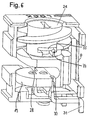
- the basic housing 9 of Figure 2 which in turn consists of insulating plastic, as the embodiment of FIG. 1, the lateral slot 18, in which the flat cable 1 is inserted.
- the actuator 10 in turn has a slide-like base and actuator body 19 which is also provided laterally with the slot 20 and which is guided telescopically in the bore 21 of the base housing 9 perpendicular to the flat cable to be contacted.
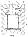
- the displacement of the base or operating body 19 in the opening 21 is not here as in Fig. 1 with a lid but by means of a screw 24 as a screw - see also Fig. 9 - realized, which has an external thread 25 and with a corresponding Internal thread 26 cooperates in a first axial region of the bore 21 of the base housing 9.
- the slot 18 in the base housing 9 has a greater axial extent perpendicular to the extension of the flat cable than the slot 20 in the base body 19 in order to realize a sufficient displaceability of the cable.
- the contacts are configured here as insulation piercing piercing contacts 30, to each of which a conductor pin 31 connects, each projecting from the base housing 9 and where the base housing 9 is mounted on a circuit board (not shown here).
- the conductor pins can be straight or angular (FIGS. 1, 11), which makes it possible to implement various embodiments in order to align the connection device on the printed circuit board either laterally or vertically upwards.
- the piercing contacts pass through holes or slots 32 in the base body and are fixed in the base housing, so that the base body is displaceable on the piercing contacts.
- the basic housing 9 with relatively large planes - here mutually perpendicular - outer surfaces is ideal for the use of placement tools, for example in pick-and-place techniques.
- the base housing 9 On the surface of the base housing 9 is a sufficiently large area for color coding or the like. Exists.
- a pointer element 27 on the externally visible screw 24 allows - possibly in combination with a housing mark or label - an easy recognizability of the switching state from the outside.
- the pointer element 27 connects laterally to an actuating slot 28 for attaching a tool, in particular a screwdriver.
- the thread 25, 26 of the screw is self-locking, which ensures both the open position and the connected position and is particularly advantageous in installation situations in which the entire device is exposed to vibration.
- the screw 24 as the member acting on the base body or the slider element allows the support of the high forces occurring during loading and unloading directly in the housing.
- the cover 22 of Fig. 1 as a screw can preferably be operated manually.
- a screwdriver operation is preferred, which is simple, quick and safe to carry out.
- the thread is designed so that with a less than a complete revolution, in particular a half turn by 180 °, a switching on or disconnection of the contact is quick and easy.
- Lock contours 28 (Fig. 10) in the slot 18 of the actuating element allow a secure pre-locking of the continuous cable to be contacted.
- the base housing may laterally of the slot of the actuating element projections 29 or the like. Be formed, which serve to realize a strain relief and Litzenabstützung.
- the screw element can release the base element 19 and thus the conductor 1 again from the contact 30, it is advantageous if the screw element and the base element 19 engage in one another in a form-fitting manner.
- This can for example - as shown in Fig. 7 or 10 to recognize - by a nut- / spring-like connection between the bolt-like screw (without tip) 24 and the base member 19 done.
Landscapes
- Coupling Device And Connection With Printed Circuit (AREA)
- Multi-Conductor Connections (AREA)
- Connections By Means Of Piercing Elements, Nuts, Or Screws (AREA)
- Cable Accessories (AREA)
Applications Claiming Priority (2)
| Application Number | Priority Date | Filing Date | Title |
|---|---|---|---|
| DE202005009442 | 2005-06-16 | ||
| DE202006000967U DE202006000967U1 (de) | 2005-06-16 | 2006-01-20 | Anschlussvorrichtung für Kabel |
Publications (3)
| Publication Number | Publication Date |
|---|---|
| EP1734612A2 true EP1734612A2 (fr) | 2006-12-20 |
| EP1734612A3 EP1734612A3 (fr) | 2010-02-10 |
| EP1734612B1 EP1734612B1 (fr) | 2011-04-27 |
Family
ID=36997584
Family Applications (1)
| Application Number | Title | Priority Date | Filing Date |
|---|---|---|---|
| EP06115502A Not-in-force EP1734612B1 (fr) | 2005-06-16 | 2006-06-14 | Dispositif de connexion pour câbles |
Country Status (3)
| Country | Link |
|---|---|
| EP (1) | EP1734612B1 (fr) |
| AT (1) | ATE507594T1 (fr) |
| DE (2) | DE202006000967U1 (fr) |
Family Cites Families (7)
| Publication number | Priority date | Publication date | Assignee | Title |
|---|---|---|---|---|
| US4403821A (en) * | 1979-03-05 | 1983-09-13 | Amp Incorporated | Wiring line tap |
| DE3545305C2 (de) * | 1985-12-20 | 1994-04-14 | Metz Albert Ria Electronic | Klemme für den Anschluß eines mehrere isolierte Leiter aufweisenden Flachbandkabels |
| US5149278A (en) * | 1991-02-22 | 1992-09-22 | Psi Telecommunications, Inc. | Terminal block |
| EP0854538A3 (fr) * | 1997-01-20 | 1999-09-08 | Fornitalia S.r.l. | Broche filetée pour la borne d'un câble électrique adapté pour créer un contact électrique à percement d'isolation |
| US5928026A (en) * | 1997-10-09 | 1999-07-27 | Bright Yin Huey Co., Ltd | Floor lamp plug device |
| WO2000055943A1 (fr) * | 1999-03-12 | 2000-09-21 | Grote & Hartmann Gmbh & Co. Kg | Connecteur electrique enfichable comprenant au moins un element de contact a guillotine constitue par une partie estampee en tole, et contre-connecteur correspondant |
| EP1313172A1 (fr) * | 2001-11-16 | 2003-05-21 | ERICH JAEGER GmbH & Co. KG | Connecteur pour des câbles |
-
2006
- 2006-01-20 DE DE202006000967U patent/DE202006000967U1/de not_active Expired - Lifetime
- 2006-06-14 AT AT06115502T patent/ATE507594T1/de active
- 2006-06-14 DE DE502006009379T patent/DE502006009379D1/de active Active
- 2006-06-14 EP EP06115502A patent/EP1734612B1/fr not_active Not-in-force
Non-Patent Citations (1)
| Title |
|---|
| None |
Also Published As
| Publication number | Publication date |
|---|---|
| EP1734612A3 (fr) | 2010-02-10 |
| DE502006009379D1 (de) | 2011-06-09 |
| ATE507594T1 (de) | 2011-05-15 |
| EP1734612B1 (fr) | 2011-04-27 |
| DE202006000967U1 (de) | 2006-10-26 |
Similar Documents
| Publication | Publication Date | Title |
|---|---|---|
| EP0726623B1 (fr) | Dispositif de connexion pour l'établissement facultatif d'une connexion électrique réutilisable, par exemple pour le branchement sur des lignes électriques à soins multiples | |
| EP2301115B1 (fr) | Dispositif de connexion électrique | |
| EP1983616B1 (fr) | Prise de bus pour un câble à bande plat et son procédé d'application | |
| EP2932566B1 (fr) | Fiche mâle d'auto-chargement | |
| EP2366212B1 (fr) | Distributeur électrique multiple | |
| WO2013167253A1 (fr) | Borne de connexion électrique | |
| EP1966855A1 (fr) | Connexion enfichable d'etablissement de contact | |
| DE102013103446A1 (de) | Steckverbindungsvorrichtung | |
| WO2008052845A2 (fr) | Connexion à fiche, en particulier pour des circuits de capteur et/ou d'actionneur | |
| EP3021421A1 (fr) | Dispositif de raccordement pour cable multiconducteur | |
| DE3135173C2 (de) | Als elektrischer Stecker oder als Steckdose oder als Kupplungsdose ausgebildetes Installationsteil | |
| DE102005012441B4 (de) | Elektrischer Steckverbinder sowie Verfahren zur Herstellung eines elektrischen Steckverbinders | |
| DE29806869U1 (de) | Elektrisches Anschlußelement | |
| EP1734612B1 (fr) | Dispositif de connexion pour câbles | |
| DE10128691B4 (de) | Anschlusseinrichtung | |
| DE69326458T2 (de) | Verbindervorrichtung für elektrische Bauteile | |
| DE10323616A1 (de) | Schnellanschließbare Steckverbindung in Spannzangentechnik | |
| DE19513645C2 (de) | Klemmenanordnung | |
| WO2024017778A1 (fr) | Connecteur enfichable configurable sans outil à direction de sortie de câble variable | |
| WO2019154709A1 (fr) | Module de connexion pour connecter un conducteur électrique et dispositif comportant un tronçon de barrette conductrice externe et un module de connexion | |
| DE19525801A1 (de) | Vorrichtung zum elektrisch leitenden Verbinden von zwei elektrischen Leitungen | |
| BE1032147B1 (de) | Sensor-Aktor-Verteiler | |
| EP1734614A2 (fr) | Dispositif de connexion pour câbles | |
| EP1286422B1 (fr) | Ensemble comprenant contacts autodénudants et douilles de sertissage | |
| EP4203197A1 (fr) | Logement destiné à recevoir une ou plusieurs bornes de connexion de conducteur et ensemble formé avec celui-ci |
Legal Events
| Date | Code | Title | Description |
|---|---|---|---|
| PUAI | Public reference made under article 153(3) epc to a published international application that has entered the european phase |
Free format text: ORIGINAL CODE: 0009012 |
|
| AK | Designated contracting states |
Kind code of ref document: A2 Designated state(s): AT BE BG CH CY CZ DE DK EE ES FI FR GB GR HU IE IS IT LI LT LU LV MC NL PL PT RO SE SI SK TR |
|
| AX | Request for extension of the european patent |
Extension state: AL BA HR MK YU |
|
| PUAL | Search report despatched |
Free format text: ORIGINAL CODE: 0009013 |
|
| AK | Designated contracting states |
Kind code of ref document: A3 Designated state(s): AT BE BG CH CY CZ DE DK EE ES FI FR GB GR HU IE IS IT LI LT LU LV MC NL PL PT RO SE SI SK TR |
|
| AX | Request for extension of the european patent |
Extension state: AL BA HR MK RS |
|
| RIC1 | Information provided on ipc code assigned before grant |
Ipc: H01R 4/30 20060101ALI20100105BHEP Ipc: H01R 4/24 20060101AFI20060927BHEP Ipc: H01R 12/08 20060101ALI20100105BHEP |
|
| 17P | Request for examination filed |
Effective date: 20100615 |
|
| 17Q | First examination report despatched |
Effective date: 20100714 |
|
| AKX | Designation fees paid |
Designated state(s): AT BE BG CH CY CZ DE DK EE ES FI FR GB GR HU IE IS IT LI LT LU LV MC NL PL PT RO SE SI SK TR |
|
| GRAP | Despatch of communication of intention to grant a patent |
Free format text: ORIGINAL CODE: EPIDOSNIGR1 |
|
| RIC1 | Information provided on ipc code assigned before grant |
Ipc: H01R 25/14 20060101ALI20101011BHEP Ipc: H01R 9/05 20060101AFI20101011BHEP |
|
| GRAS | Grant fee paid |
Free format text: ORIGINAL CODE: EPIDOSNIGR3 |
|
| GRAA | (expected) grant |
Free format text: ORIGINAL CODE: 0009210 |
|
| AK | Designated contracting states |
Kind code of ref document: B1 Designated state(s): AT BE BG CH CY CZ DE DK EE ES FI FR GB GR HU IE IS IT LI LT LU LV MC NL PL PT RO SE SI SK TR |
|
| REG | Reference to a national code |
Ref country code: GB Ref legal event code: FG4D Free format text: NOT ENGLISH |
|
| REG | Reference to a national code |
Ref country code: CH Ref legal event code: EP |
|
| REG | Reference to a national code |
Ref country code: IE Ref legal event code: FG4D Free format text: LANGUAGE OF EP DOCUMENT: GERMAN |
|
| REF | Corresponds to: |
Ref document number: 502006009379 Country of ref document: DE Date of ref document: 20110609 Kind code of ref document: P |
|
| REG | Reference to a national code |
Ref country code: DE Ref legal event code: R096 Ref document number: 502006009379 Country of ref document: DE Effective date: 20110609 |
|
| REG | Reference to a national code |
Ref country code: NL Ref legal event code: VDEP Effective date: 20110427 |
|
| LTIE | Lt: invalidation of european patent or patent extension |
Effective date: 20110427 |
|
| PG25 | Lapsed in a contracting state [announced via postgrant information from national office to epo] |
Ref country code: PT Free format text: LAPSE BECAUSE OF FAILURE TO SUBMIT A TRANSLATION OF THE DESCRIPTION OR TO PAY THE FEE WITHIN THE PRESCRIBED TIME-LIMIT Effective date: 20110829 Ref country code: SE Free format text: LAPSE BECAUSE OF FAILURE TO SUBMIT A TRANSLATION OF THE DESCRIPTION OR TO PAY THE FEE WITHIN THE PRESCRIBED TIME-LIMIT Effective date: 20110427 Ref country code: LT Free format text: LAPSE BECAUSE OF FAILURE TO SUBMIT A TRANSLATION OF THE DESCRIPTION OR TO PAY THE FEE WITHIN THE PRESCRIBED TIME-LIMIT Effective date: 20110427 |
|
| REG | Reference to a national code |
Ref country code: IE Ref legal event code: FD4D |
|
| PG25 | Lapsed in a contracting state [announced via postgrant information from national office to epo] |
Ref country code: SI Free format text: LAPSE BECAUSE OF FAILURE TO SUBMIT A TRANSLATION OF THE DESCRIPTION OR TO PAY THE FEE WITHIN THE PRESCRIBED TIME-LIMIT Effective date: 20110427 Ref country code: IS Free format text: LAPSE BECAUSE OF FAILURE TO SUBMIT A TRANSLATION OF THE DESCRIPTION OR TO PAY THE FEE WITHIN THE PRESCRIBED TIME-LIMIT Effective date: 20110827 Ref country code: GR Free format text: LAPSE BECAUSE OF FAILURE TO SUBMIT A TRANSLATION OF THE DESCRIPTION OR TO PAY THE FEE WITHIN THE PRESCRIBED TIME-LIMIT Effective date: 20110728 Ref country code: ES Free format text: LAPSE BECAUSE OF FAILURE TO SUBMIT A TRANSLATION OF THE DESCRIPTION OR TO PAY THE FEE WITHIN THE PRESCRIBED TIME-LIMIT Effective date: 20110807 Ref country code: LV Free format text: LAPSE BECAUSE OF FAILURE TO SUBMIT A TRANSLATION OF THE DESCRIPTION OR TO PAY THE FEE WITHIN THE PRESCRIBED TIME-LIMIT Effective date: 20110427 Ref country code: CY Free format text: LAPSE BECAUSE OF FAILURE TO SUBMIT A TRANSLATION OF THE DESCRIPTION OR TO PAY THE FEE WITHIN THE PRESCRIBED TIME-LIMIT Effective date: 20110427 Ref country code: FI Free format text: LAPSE BECAUSE OF FAILURE TO SUBMIT A TRANSLATION OF THE DESCRIPTION OR TO PAY THE FEE WITHIN THE PRESCRIBED TIME-LIMIT Effective date: 20110427 |
|
| PG25 | Lapsed in a contracting state [announced via postgrant information from national office to epo] |
Ref country code: NL Free format text: LAPSE BECAUSE OF FAILURE TO SUBMIT A TRANSLATION OF THE DESCRIPTION OR TO PAY THE FEE WITHIN THE PRESCRIBED TIME-LIMIT Effective date: 20110427 |
|
| BERE | Be: lapsed |
Owner name: WEIDMULLER INTERFACE G.M.B.H. & CO. KG Effective date: 20110630 |
|
| PG25 | Lapsed in a contracting state [announced via postgrant information from national office to epo] |
Ref country code: EE Free format text: LAPSE BECAUSE OF FAILURE TO SUBMIT A TRANSLATION OF THE DESCRIPTION OR TO PAY THE FEE WITHIN THE PRESCRIBED TIME-LIMIT Effective date: 20110427 Ref country code: IE Free format text: LAPSE BECAUSE OF FAILURE TO SUBMIT A TRANSLATION OF THE DESCRIPTION OR TO PAY THE FEE WITHIN THE PRESCRIBED TIME-LIMIT Effective date: 20110427 Ref country code: CZ Free format text: LAPSE BECAUSE OF FAILURE TO SUBMIT A TRANSLATION OF THE DESCRIPTION OR TO PAY THE FEE WITHIN THE PRESCRIBED TIME-LIMIT Effective date: 20110427 |
|
| REG | Reference to a national code |
Ref country code: CH Ref legal event code: PL |
|
| PG25 | Lapsed in a contracting state [announced via postgrant information from national office to epo] |
Ref country code: SK Free format text: LAPSE BECAUSE OF FAILURE TO SUBMIT A TRANSLATION OF THE DESCRIPTION OR TO PAY THE FEE WITHIN THE PRESCRIBED TIME-LIMIT Effective date: 20110427 Ref country code: PL Free format text: LAPSE BECAUSE OF FAILURE TO SUBMIT A TRANSLATION OF THE DESCRIPTION OR TO PAY THE FEE WITHIN THE PRESCRIBED TIME-LIMIT Effective date: 20110427 Ref country code: RO Free format text: LAPSE BECAUSE OF FAILURE TO SUBMIT A TRANSLATION OF THE DESCRIPTION OR TO PAY THE FEE WITHIN THE PRESCRIBED TIME-LIMIT Effective date: 20110427 Ref country code: DK Free format text: LAPSE BECAUSE OF FAILURE TO SUBMIT A TRANSLATION OF THE DESCRIPTION OR TO PAY THE FEE WITHIN THE PRESCRIBED TIME-LIMIT Effective date: 20110427 |
|
| PLBE | No opposition filed within time limit |
Free format text: ORIGINAL CODE: 0009261 |
|
| STAA | Information on the status of an ep patent application or granted ep patent |
Free format text: STATUS: NO OPPOSITION FILED WITHIN TIME LIMIT |
|
| REG | Reference to a national code |
Ref country code: FR Ref legal event code: ST Effective date: 20120229 |
|
| GBPC | Gb: european patent ceased through non-payment of renewal fee |
Effective date: 20110727 |
|
| PG25 | Lapsed in a contracting state [announced via postgrant information from national office to epo] |
Ref country code: BE Free format text: LAPSE BECAUSE OF NON-PAYMENT OF DUE FEES Effective date: 20110630 |
|
| 26N | No opposition filed |
Effective date: 20120130 |
|
| REG | Reference to a national code |
Ref country code: DE Ref legal event code: R119 Ref document number: 502006009379 Country of ref document: DE Effective date: 20120103 |
|
| PG25 | Lapsed in a contracting state [announced via postgrant information from national office to epo] |
Ref country code: DE Free format text: LAPSE BECAUSE OF NON-PAYMENT OF DUE FEES Effective date: 20120103 Ref country code: CH Free format text: LAPSE BECAUSE OF NON-PAYMENT OF DUE FEES Effective date: 20110630 Ref country code: LI Free format text: LAPSE BECAUSE OF NON-PAYMENT OF DUE FEES Effective date: 20110630 Ref country code: FR Free format text: LAPSE BECAUSE OF NON-PAYMENT OF DUE FEES Effective date: 20110630 |
|
| PG25 | Lapsed in a contracting state [announced via postgrant information from national office to epo] |
Ref country code: IT Free format text: LAPSE BECAUSE OF FAILURE TO SUBMIT A TRANSLATION OF THE DESCRIPTION OR TO PAY THE FEE WITHIN THE PRESCRIBED TIME-LIMIT Effective date: 20110427 |
|
| PG25 | Lapsed in a contracting state [announced via postgrant information from national office to epo] |
Ref country code: GB Free format text: LAPSE BECAUSE OF NON-PAYMENT OF DUE FEES Effective date: 20110727 |
|
| REG | Reference to a national code |
Ref country code: AT Ref legal event code: MM01 Ref document number: 507594 Country of ref document: AT Kind code of ref document: T Effective date: 20110614 |
|
| PG25 | Lapsed in a contracting state [announced via postgrant information from national office to epo] |
Ref country code: AT Free format text: LAPSE BECAUSE OF NON-PAYMENT OF DUE FEES Effective date: 20110614 |
|
| PG25 | Lapsed in a contracting state [announced via postgrant information from national office to epo] |
Ref country code: MC Free format text: LAPSE BECAUSE OF NON-PAYMENT OF DUE FEES Effective date: 20110630 |
|
| PG25 | Lapsed in a contracting state [announced via postgrant information from national office to epo] |
Ref country code: LU Free format text: LAPSE BECAUSE OF NON-PAYMENT OF DUE FEES Effective date: 20110614 |
|
| PG25 | Lapsed in a contracting state [announced via postgrant information from national office to epo] |
Ref country code: BG Free format text: LAPSE BECAUSE OF FAILURE TO SUBMIT A TRANSLATION OF THE DESCRIPTION OR TO PAY THE FEE WITHIN THE PRESCRIBED TIME-LIMIT Effective date: 20110727 |
|
| PG25 | Lapsed in a contracting state [announced via postgrant information from national office to epo] |
Ref country code: TR Free format text: LAPSE BECAUSE OF FAILURE TO SUBMIT A TRANSLATION OF THE DESCRIPTION OR TO PAY THE FEE WITHIN THE PRESCRIBED TIME-LIMIT Effective date: 20110427 |
|
| PG25 | Lapsed in a contracting state [announced via postgrant information from national office to epo] |
Ref country code: HU Free format text: LAPSE BECAUSE OF FAILURE TO SUBMIT A TRANSLATION OF THE DESCRIPTION OR TO PAY THE FEE WITHIN THE PRESCRIBED TIME-LIMIT Effective date: 20110427 |