EP1734802A2 - Tête d'insertion pour automate d'insertion de composants électriques sur des subtrats. - Google Patents
Tête d'insertion pour automate d'insertion de composants électriques sur des subtrats. Download PDFInfo
- Publication number
- EP1734802A2 EP1734802A2 EP06115056A EP06115056A EP1734802A2 EP 1734802 A2 EP1734802 A2 EP 1734802A2 EP 06115056 A EP06115056 A EP 06115056A EP 06115056 A EP06115056 A EP 06115056A EP 1734802 A2 EP1734802 A2 EP 1734802A2
- Authority
- EP
- European Patent Office
- Prior art keywords
- linear motors
- mounting surface
- linear
- placement
- placement head
- Prior art date
- Legal status (The legal status is an assumption and is not a legal conclusion. Google has not performed a legal analysis and makes no representation as to the accuracy of the status listed.)
- Withdrawn
Links
Images


Classifications
-
- H—ELECTRICITY
- H05—ELECTRIC TECHNIQUES NOT OTHERWISE PROVIDED FOR
- H05K—PRINTED CIRCUITS; CASINGS OR CONSTRUCTIONAL DETAILS OF ELECTRIC APPARATUS; MANUFACTURE OF ASSEMBLAGES OF ELECTRICAL COMPONENTS
- H05K13/00—Apparatus or processes specially adapted for manufacturing or adjusting assemblages of electric components
- H05K13/04—Mounting of components, e.g. of leadless components
- H05K13/0404—Pick-and-place heads or apparatus, e.g. with jaws
- H05K13/0413—Pick-and-place heads or apparatus, e.g. with jaws with orientation of the component while holding it; Drive mechanisms for gripping tools, e.g. lifting, lowering or turning of gripping tools
-
- H—ELECTRICITY
- H05—ELECTRIC TECHNIQUES NOT OTHERWISE PROVIDED FOR
- H05K—PRINTED CIRCUITS; CASINGS OR CONSTRUCTIONAL DETAILS OF ELECTRIC APPARATUS; MANUFACTURE OF ASSEMBLAGES OF ELECTRICAL COMPONENTS
- H05K13/00—Apparatus or processes specially adapted for manufacturing or adjusting assemblages of electric components
- H05K13/04—Mounting of components, e.g. of leadless components
- H05K13/0404—Pick-and-place heads or apparatus, e.g. with jaws
- H05K13/0408—Incorporating a pick-up tool
- H05K13/041—Incorporating a pick-up tool having multiple pick-up tools
Definitions
- the invention relates to a placement for a placement for loading of substrates with electrical components, in particular a so-called matrix or Zeilenbe LinkedIn.
- substrates or printed circuit boards are equipped with electrical components in a placement machine.
- the substrates are transported over a transport route to a placement of the placement, stocked there and then transported away from Be Glaplatz.
- Side of the transport path feeders are provided in a feed area, which provide the electrical components.
- the placement machine has a placement head, which can be moved parallel to the placement plane between the feed area and the placement area by means of a positioning system. In the process, the placement head picks up the components provided by the feed devices and moves into the placement area in order to equip the substrates there with the components. In this case, so-called matrix or Zeilenbe consortium are used.
- These types of placement heads usually have a plurality of gripper units, which are arranged in rows or in a matrix next to one another and are individually displaceable perpendicular to the placement plane in the direction of the substrates.
- the movement of the individual gripper units is often done by means of linear motors.
- a well-known matrix placement head is equipped so that each individual gripper unit has its own complete linear motor.
- the individual motors are each designed so that between two opposing stator plates, each consisting of an iron backplate and mounted thereon permanent magnet 20, an energizable, movably mounted coil part is arranged.
- a gripper of the gripper unit is with the mobile coil part firmly connected and thereby movable perpendicular to the placement plane to accommodate components or settle them on the substrate.
- this type of matrix placement head proves to be expensive to manufacture and time consuming to assemble since all linear motors must be assembled separately.
- the structure described requires a relatively large amount of space.
- An assembly head comprises a mounting surface, a plurality of linear guides and a plurality of gripper units. Each of the gripper units is in each case coupled to one of the linear guides and displaceable along this relative to the mounting surface.
- the placement head further comprises a plurality of linear motors, each with a handset and a stationary part, wherein in each case a linear motor is assigned to one of the gripper units.
- the mobile parts of the linear motors are firmly connected to the respective gripper unit to move along the linear guides.
- the placement head according to the invention is characterized in particular by the fact that a common mounting surface is provided for fastening the stationary parts of a plurality of linear motors, but at least two linear motors. This makes it possible to carry out the stationary parts of several linear motors together with the common mounting surface as a single pre-assembled module or assembly unit, whereby the assembly can be performed easier, faster and cheaper.
- the placement head can also be designed according to claim 2 in that the stationary parts of the linear motors are arranged on the mounting surface in a common plane are.
- the stationary parts of the linear motors may be fastened together on a side surface of a simple mounting plate.
- Mutually facing surfaces of the stationary part and the associated mobile part of each linear motor are arranged parallel to the mounting surface. This allows a further simplification of the construction of the placement and thus a further reduction of costs and space.
- the mounting surface is formed as a first common ferromagnetic yoke plate for the linear motors.
- the ferromagnetic backplate has a material with high magnetic flux conductivity, which significantly increases the efficiency of the linear motors.
- the mounting surface or the mounting plate thereby simultaneously assumes the function of the return plate for the linear motors, which brings a further summary of components of the linear motors with it.
- the stationary parts of the linear motors are energizable coil elements and the mobile parts are permanent magnets.
- the permanent magnets are to be moved, whereas the coil elements to be energized are fixedly mounted on the mounting surface (moving magnet).
- the fact that the coils make up the stationary part of the linear motor, the claims and thus the cost of the leading to the coil elements power lines and the necessary plug connections are set considerably lower than in the opposite case, in which the coil elements represent the moving parts of the linear motors , As a result, the costs of the placement head can be reduced and the reliability can be increased.
- the placement head can be configured such that a printed circuit board is mounted on the mounting surface, glued, for example, which has leading to the also arranged on the mounting surface coil elements power lines to connect the coil elements with an external power supply.
- the power lines can lead to a common power connector of the circuit board, so that only a single plug connection to the power supply is needed.
- the placement head may further comprise a second ferromagnetic yoke plate, which is arranged such that the mobile parts of a plurality of linear motors in a gap formed between the first ferromagnetic yoke plate and the second ferromagnetic yoke plate are movable.
- the second return plate is designed as a common return plate for several linear motors, so that here again individual components of the linear motors are combined into one component.
- the second return plate can be configured such that the force acting on the mobile parts of the linear motors resulting magnetic force is reduced perpendicular to a direction of displacement of the gripper units. Without the second return plate, the load on the linear guides on the magnetic force acting between the permanent magnet 20 and the coil elements perpendicular to the direction of movement would be significant. However, the arrangement of a second return plate according to claim 7, the bearing load can be significantly reduced.
- a placement head 6 can be moved parallel to a placement plane by means of a two-dimensional positioning system.
- the positioning system comprises a cantilevered support arm 7, which is displaceable by means of a suitable drive along a guide device 8 (arrow x).
- the placement head 6 with a further drive in one direction (arrow y) is arranged perpendicular to the guide device 8 movable.
- the placement head 6 is first moved into the feed area to receive components 5, whereupon it moves back into the placement area in order to deposit the components 5 on the substrate 2.
- the placement head 6 has a box-shaped housing 9.
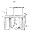
- FIG. 9 For better illustration of the internal structure of the placement head 6 in Figure 2 but without front cover and in the Figures 3 to 5 additionally shown without upper cover plate 10 and structures 11.
- the exemplary embodiment is a so-called matrix placement head 6 with six gripper units 12, which are arranged in two rows of three gripper units 12 each.
- the two rows of three gripper units 12 are arranged mirror-symmetrically and have an identical structure.
- the following description is limited in part to a series of gripper units 12, but applies analogously to the other series.
- the gripper units 12 may for example have suction pads 13, the tip 14 of vacuum generator modules 11, which are shown schematically in Figure 2 as structures 11 on the upper cover plate 10 of the placement head 6, optionally with vacuum or compressed air can be applied.
- the placement head 6 has a mounting surface 15 which can be formed, for example, by a side wall 15 of the housing 9 of the placement head.
- the gripper units 12 are coupled to linear guides 16 and along this in a direction of displacement (arrow Z) perpendicular to the placement plane of the placement machine 1 (see Figure 1) displaceable to receive components 5 and settle on the substrate 2.
- a gripper housing 17 a known trained rotary drive can be provided which rotatably drives the hook tip formed as a hollow shaft to bring recorded components 5 in a desired angular position.
- the placement head 6 further comprises a plurality of linear motors 18, wherein each gripper unit 12 is associated with a respective linear motor 18 to move along the linear guide 16 relative to the mounting surface 15.
- the linear motors 18 include, inter alia, stationary parts 19, which on the mounting plate are fixed, and handsets 20, which are connected to the gripper units 12 and thereby are also mounted relative to the mounting surface 15 movable.
- the stationary parts 19 essentially consist of energizable coil elements, whereas the mobile parts are permanent magnets 20. However, it is also an embodiment conceivable in which the coil elements 19 represent the handsets 20 and the permanent magnets 20, the stationary parts 19 of the linear motors 18.
- the embodiment shown in the embodiment has the advantage that the power supply of the attached to the mounting surface 15 coil elements 19 is much easier to make, as in the case that the coil elements 19 are designed as movable handsets 20. In this case, the requirements for the plug connection and the risk of a defect would be considerably greater.
- the stationary parts 19 of a plurality of linear motors 18 are fixedly connected to the mounting surface 15. More specifically, the coil elements 19 of the linear motors 18 of a row are fixed to the respective side wall 15 of the housing 9 which constitutes the mounting surface.
- the side wall 15 thereby forms a common mounting surface for the coil elements or stationary parts of several linear motors.
- the side wall 15 of the housing 9 of the placement head 6 may have a material with high magnetic flux conductivity, whereby the side wall 15 simultaneously assumes the function of a first common ferromagnetic yoke plate 15 for the three linear motors 18 of a row. Due to the magnetic inference, the efficiency of the linear motors 18 is significantly increased.
- the stationary parts 19 and the coil elements 19 of a plurality of linear motors 18 are therefore arranged on the common mounting surface 15 in the form of a first ferromagnetic yoke plate 15 in a plane next to each other.
- Mutually facing surfaces of the mobile parts 20 (or permanent magnets 20) and the stationary parts 19 (or coil elements 19) of each linear motor 18 are arranged parallel to the mounting surface 15.
- a printed circuit board 21 with integrated power supply lines (not shown) is additionally attached, which connect the coil elements 19 with a common power connection 22 of the circuit board 21.
- This construction ensures a very reliable and easy power supply of the coil elements 19 via the common power connection 22, which brings advantages in particular during installation and lowers the cost of manufacturing.
- the placement head 6 further has a second ferromagnetic yoke plate 23, which is arranged such that the permanent magnets 20 of a plurality of linear motors 18 are movable in a gap formed between the first ferromagnetic yoke plate 15 and the second ferromagnetic yoke plate 23.
- the second ferromagnetic yoke plate 23 is arranged parallel to the first ferromagnetic yoke plate 15.
- the second ferromagnetic return plate 23 is designed in such a way that the resultant magnetic force directed in a direction perpendicular to the displacement direction (in FIGS. 2-4 arrow z) acts on the permanent magnets 20 (or mobile parts 20) of the linear motors 18 is reduced.
- the resulting magnetic force results from the sum of the magnetic force acting between the permanent magnets 20 and the first return plate 15 and the oppositely directed magnetic force acting between the permanent magnets 20 and the second return plate 23.
- the magnetic forces that act on the permanent magnets on the one hand by the distance between the permanent magnet 20 and the first return plate 15 and the second return plate 23 and on the other hand of the size the magnetic active surface between the permanent magnet 20 and the first and the second ferromagnetic yoke plate 23 dependent.
- the magnetic effective area results from the overlapping of the surfaces in a projection of the permanent magnets 20 perpendicular to the respective ferromagnetic yoke plate 15 and 23.
- the magnetic forces between the permanent magnet 20 and the first and second return plate 15 and 23, respectively grow smaller becoming the distance and increasing magnetic effective area.
- the distance between the permanent magnet 20 and the first ferromagnetic yoke plate 15 is significantly larger than the distance between the permanent magnet 20 and the second ferromagnetic yoke plate 23.
- the magnetic active surface between the permanent magnet 20 and the first ferromagnetic yoke plate 15 is significantly larger than the magnetic effective area between the permanent magnet 20 and the second ferromagnetic return plate 23.
- the second ferromagnetic yoke plate 23 therefore formed and arranged so that by the distance and the magnetic effective area between the permanent magnet 20 and the second ferromagnetic yoke plate 23rd certain magnetic force, the oppositely directed magnetic force between the permanent magnet 20 and the first ferromagnetic yoke plate 15 largely compensated. As a result, the bearing load on the linear guides 16 is minimized.
- the coil elements 19 of a plurality of motors may be used together with the common first ferromagnetic yoke plate 15 and the common circuit board 21 are constructed and preassembled with the common power connector 22 as a mounting unit. This not only has cost advantages, but also simplifies the assembly of the placement head considerably.
- a length measuring device (not shown) are mounted, by means of which the displacement length of the linear motors 18 along the linear guide 16 relative to the mounting surface 15 can be detected.
- the linear scale on the mobile part of the linear motor or on the gripper unit 12 and to mount the sensor on the printed circuit board 21.
- the wiring for powering the sensor and for transferring data from the sensor to a computer unit may be provided on the circuit board 21.
Landscapes
- Engineering & Computer Science (AREA)
- Manufacturing & Machinery (AREA)
- Microelectronics & Electronic Packaging (AREA)
- Supply And Installment Of Electrical Components (AREA)
Applications Claiming Priority (1)
| Application Number | Priority Date | Filing Date | Title |
|---|---|---|---|
| DE102005027901A DE102005027901A1 (de) | 2005-06-16 | 2005-06-16 | Bestückkopf für einen Bestückautomaten zum Bestücken von Substraten mit elektrischen Bauteilen |
Publications (2)
| Publication Number | Publication Date |
|---|---|
| EP1734802A2 true EP1734802A2 (fr) | 2006-12-20 |
| EP1734802A3 EP1734802A3 (fr) | 2007-12-05 |
Family
ID=37074249
Family Applications (1)
| Application Number | Title | Priority Date | Filing Date |
|---|---|---|---|
| EP06115056A Withdrawn EP1734802A3 (fr) | 2005-06-16 | 2006-06-07 | Tête d'insertion pour automate d'insertion de composants électriques sur des subtrats. |
Country Status (2)
| Country | Link |
|---|---|
| EP (1) | EP1734802A3 (fr) |
| DE (1) | DE102005027901A1 (fr) |
Cited By (2)
| Publication number | Priority date | Publication date | Assignee | Title |
|---|---|---|---|---|
| EP2389059A3 (fr) * | 2010-05-19 | 2013-08-14 | ASM Assembly Systems GmbH & Co. KG | Tête à implanter pour un automate d'alimentation, automate d'alimentation et procédé d'alimentation |
| CN108029239A (zh) * | 2015-10-01 | 2018-05-11 | 雅马哈发动机株式会社 | 旋转头以及表面安装机 |
Family Cites Families (4)
| Publication number | Priority date | Publication date | Assignee | Title |
|---|---|---|---|---|
| US6343415B1 (en) * | 1996-12-25 | 2002-02-05 | Matsushita Electric Industrial Co., Ltd. | Part holding head, part mounting device and part holding method |
| JP3981478B2 (ja) * | 1998-09-30 | 2007-09-26 | ヤマハ発動機株式会社 | 電子部品装着装置 |
| WO2002026011A2 (fr) * | 2000-09-19 | 2002-03-28 | Matsushita Electric Industrial Co., Ltd. | Dispositif d'aspiration de composants, appareil et procede de montage de composants |
| JP3772808B2 (ja) * | 2002-08-29 | 2006-05-10 | 株式会社村田製作所 | 部品装着装置 |
-
2005
- 2005-06-16 DE DE102005027901A patent/DE102005027901A1/de not_active Ceased
-
2006
- 2006-06-07 EP EP06115056A patent/EP1734802A3/fr not_active Withdrawn
Cited By (5)
| Publication number | Priority date | Publication date | Assignee | Title |
|---|---|---|---|---|
| EP2389059A3 (fr) * | 2010-05-19 | 2013-08-14 | ASM Assembly Systems GmbH & Co. KG | Tête à implanter pour un automate d'alimentation, automate d'alimentation et procédé d'alimentation |
| CN108029239A (zh) * | 2015-10-01 | 2018-05-11 | 雅马哈发动机株式会社 | 旋转头以及表面安装机 |
| JPWO2017056291A1 (ja) * | 2015-10-01 | 2018-08-02 | ヤマハ発動機株式会社 | ロータリーヘッド、及び、表面実装機 |
| CN108029239B (zh) * | 2015-10-01 | 2019-12-20 | 雅马哈发动机株式会社 | 旋转头以及表面安装机 |
| US10874040B2 (en) | 2015-10-01 | 2020-12-22 | Yamaha Hatsudoki Kabushiki Kaisha | Rotary head and surface mounter |
Also Published As
| Publication number | Publication date |
|---|---|
| DE102005027901A1 (de) | 2006-12-28 |
| EP1734802A3 (fr) | 2007-12-05 |
Similar Documents
| Publication | Publication Date | Title |
|---|---|---|
| DE69835697T2 (de) | Bauteile-bestückungsvorrichtung und bauteilezufuhrvorrichtung | |
| DE10129836A1 (de) | Vorrichtung und Verfahren zur Bauteilmontage | |
| DE69606963T2 (de) | Automatische Bestückungseinrichtung für elektronische Teile | |
| EP0962125B1 (fr) | Dispositif permettant de fabriquer des composants electriques | |
| DE102012018203A1 (de) | Linearmotor zum Anheben und Absenken von Saugdüse, und Montagevorrichtung für elektronische Komponente | |
| DE10157225A1 (de) | Verfahren und Vorrichtung zur Flächenmontage | |
| DE102016203560B4 (de) | Aktoranordnung mit einem Sensormodul für einen Aktor mit verschiebbarem Anker | |
| EP2389059B1 (fr) | Tête à implanter pour un automate d'alimentation, automate d'alimentation et procédé d'alimentation | |
| WO2005034602A1 (fr) | Tete d'insertion a unite de prehension pour l'insertion de substrats presentant des composants electriques | |
| EP0153632B1 (fr) | Montage d'un connecteur électrique à un appareil de mesure | |
| EP1734802A2 (fr) | Tête d'insertion pour automate d'insertion de composants électriques sur des subtrats. | |
| EP2848107B1 (fr) | Dispositif de montage de composants electriques sur des substrats | |
| WO2025104033A1 (fr) | Module de stator et système d'entraînement plan | |
| DE69304493T2 (de) | Verfahren und Gerät zum Montieren von Verbindern | |
| EP1284095A1 (fr) | Dispositif pour implanter des composants electriques sur des substrats | |
| EP1284096B1 (fr) | Dispositif pour implanter des composants electriques sur des substrats | |
| WO2004021757A1 (fr) | Dispositif de deplacement selectif de dispositifs de retenue et tete d'insertion pour le transport de composants | |
| DE102013204590B3 (de) | Erkennen eines schwingenden Bauelementeträgers während einer Bestückung mit Bauelementen | |
| DE112022007819T5 (de) | Leiterplattentransportvorrichtung, Bestückungsautomat und Leiterplattentransportverfahren | |
| DE102024111273B3 (de) | Transfer von Shuttle-Bestückmodulen zwischen einer Führungsbahn und einer Aufnahmestruktur in einem Shuttle-Bestückmodul-Bestücksystems | |
| DE102011054105A1 (de) | Verbindungsleiterplatte | |
| DE112021008455T5 (de) | Maschine zur Montage von Komponenten und Verfahren zur Herstellung von Substraten | |
| DE10304970B4 (de) | Positioniereinheit mit einem Kraftsensor | |
| EP1449416B1 (fr) | Dispositif de montage pour composants comprenant une pince aspirante | |
| DE102008049540B3 (de) | Anordnung zum Wechseln eines Bestückkopfs und Bestückautomat |
Legal Events
| Date | Code | Title | Description |
|---|---|---|---|
| PUAI | Public reference made under article 153(3) epc to a published international application that has entered the european phase |
Free format text: ORIGINAL CODE: 0009012 |
|
| AK | Designated contracting states |
Kind code of ref document: A2 Designated state(s): AT BE BG CH CY CZ DE DK EE ES FI FR GB GR HU IE IS IT LI LT LU LV MC NL PL PT RO SE SI SK TR |
|
| AX | Request for extension of the european patent |
Extension state: AL BA HR MK YU |
|
| PUAL | Search report despatched |
Free format text: ORIGINAL CODE: 0009013 |
|
| AK | Designated contracting states |
Kind code of ref document: A3 Designated state(s): AT BE BG CH CY CZ DE DK EE ES FI FR GB GR HU IE IS IT LI LT LU LV MC NL PL PT RO SE SI SK TR |
|
| AX | Request for extension of the european patent |
Extension state: AL BA HR MK YU |
|
| AKX | Designation fees paid | ||
| STAA | Information on the status of an ep patent application or granted ep patent |
Free format text: STATUS: THE APPLICATION IS DEEMED TO BE WITHDRAWN |
|
| 18D | Application deemed to be withdrawn |
Effective date: 20080606 |
|
| REG | Reference to a national code |
Ref country code: DE Ref legal event code: 8566 |