EP1735193B1 - Scheibenwischvorrichtung, insbesondere für ein kraftfahrzeug - Google Patents
Scheibenwischvorrichtung, insbesondere für ein kraftfahrzeug Download PDFInfo
- Publication number
- EP1735193B1 EP1735193B1 EP05716687A EP05716687A EP1735193B1 EP 1735193 B1 EP1735193 B1 EP 1735193B1 EP 05716687 A EP05716687 A EP 05716687A EP 05716687 A EP05716687 A EP 05716687A EP 1735193 B1 EP1735193 B1 EP 1735193B1
- Authority
- EP
- European Patent Office
- Prior art keywords
- slot
- wiper device
- windscreen wiper
- installation direction
- damping element
- Prior art date
- Legal status (The legal status is an assumption and is not a legal conclusion. Google has not performed a legal analysis and makes no representation as to the accuracy of the status listed.)
- Expired - Lifetime
Links
- 238000013016 damping Methods 0.000 claims description 27
- 238000009434 installation Methods 0.000 claims description 9
- 239000002184 metal Substances 0.000 claims description 4
- 239000000853 adhesive Substances 0.000 description 1
- 230000001070 adhesive effect Effects 0.000 description 1
- 238000004512 die casting Methods 0.000 description 1
- 238000001746 injection moulding Methods 0.000 description 1
- 238000004519 manufacturing process Methods 0.000 description 1
- 230000008719 thickening Effects 0.000 description 1
Images

Classifications
-
- B—PERFORMING OPERATIONS; TRANSPORTING
- B60—VEHICLES IN GENERAL
- B60S—SERVICING, CLEANING, REPAIRING, SUPPORTING, LIFTING, OR MANOEUVRING OF VEHICLES, NOT OTHERWISE PROVIDED FOR
- B60S1/00—Cleaning of vehicles
- B60S1/02—Cleaning windscreens, windows or optical devices
- B60S1/04—Wipers or the like, e.g. scrapers
- B60S1/043—Attachment of the wiper assembly to the vehicle
- B60S1/0441—Attachment of the wiper assembly to the vehicle characterised by the attachment means
- B60S1/0447—Attachment of the wiper assembly to the vehicle characterised by the attachment means non-screw fixation, (e.g. snap-in, bayonnet-type..)
-
- B—PERFORMING OPERATIONS; TRANSPORTING
- B60—VEHICLES IN GENERAL
- B60S—SERVICING, CLEANING, REPAIRING, SUPPORTING, LIFTING, OR MANOEUVRING OF VEHICLES, NOT OTHERWISE PROVIDED FOR
- B60S1/00—Cleaning of vehicles
- B60S1/02—Cleaning windscreens, windows or optical devices
- B60S1/04—Wipers or the like, e.g. scrapers
- B60S1/043—Attachment of the wiper assembly to the vehicle
- B60S1/0441—Attachment of the wiper assembly to the vehicle characterised by the attachment means
- B60S1/0444—Attachment of the wiper assembly to the vehicle characterised by the attachment means comprising vibration or noise absorbing means
Definitions
- the invention is based on a windshield wiper device, in particular for a motor vehicle, according to the preamble of claim 1.
- the windscreen wiper system on a support structure for a drive device.
- a number of first fasteners is provided, which protrude in a first direction from the support structure.
- a second direction which extends at an angle between 45 and 135 degrees to the first direction, preferably at an angle of 90 degrees, protrude a number of second fasteners.
- the fastening elements are designed as cylindrical plug-in pins which are connected at one end to the support structure and are inserted with their free end into a receiving opening of a rubber-elastic damping element.
- the mounting opening may be in an angled or deep-drawn tab welded to the vehicle body.
- the free end of the spigot may have a preferably conical thickening in order to fix the same in the damping element by latching can. Since the mounting directions of the first and second fastening elements are at an angle, it is not excluded that the support structure after assembly is under a voltage that is transmitted to the adjacent parts of the vehicle body.
- a windshield wiper device according to the preamble of claim 1 is known from the document WO-A-03/097419 known.
- the damping element is firmly connected to the fastening element. It can be used in a first mounting direction in the receiving opening and engages by a movement in a second mounting direction transverse to the first edge of the receiving opening with a slot. This is arranged in a component which has a relative to the damping element hard surface and is fixedly connected to the damping element. Due to the low coefficient of friction between the hard surface of the slot and the vehicle body resulting low assembly forces in the second mounting direction, so that the windshield wiper device according to the invention can be mounted without great effort. Thus, the edge of the receiving opening can be easily inserted into the slot, this has at its opening an extension.
- the windshield wiper device usually has to be fixed in the end position so that the fastening element with the damping element can not be loosened in the opposite direction.
- a locking element for example in the form of a pin or a screw, can be provided, which is arranged in the first mounting direction and connects the drive element to the vehicle body. It expediently also has vibration-damping measures. However, this means a high production and assembly costs.
- the bracket has two substantially parallel legs which define the slot, and one of which has a latching nose which engages in an opening of the opposite leg.
- the locking lug on the edge of the receiving opening is pushed back by the body panel and engages on reaching the end position in a corresponding latching opening of the body panel.
- the latch In order to push back the latch easily, it has a flatter edge in the second mounting direction, while against the second mounting direction a steeper flank of the detent ensures that the end position is securely locked.
- the bracket has a second latching lug, which lies in the second mounting direction behind the first latching lug and engages with two steep, transverse to the second mounting direction flanks in an opening of the opposite leg.
- the second latch also engages in a detent hole of the vehicle body. While both detents are disengaged by the flat flank of the first detent, and the first detent coarsely positions the windshield wiper device in the final position, the second detent allows more accurate positioning of the windshield wiper relative to the corresponding detent hole in the vehicle body.
- the second detent in the longitudinal section of the bracket advantageously on an M-shaped or w-shaped configuration.
- the bracket which is advantageously made of plastic or sheet metal, can be pressed into a recess of the damping element, glued, cast or vulcanized or held positively.
- the slot of the bracket is matched to the thickness of the body panel or a bracket that the body panel in the assembled state rests under a bias on the inner sides of the bracket.
- a holding element made of plastic is inserted into a recess of the damping element, having a slot for receiving the body panel, wherein one side of the slot has a latching nose which projects into a recess on the opposite side of the slot.
- the holding element may be divided in the second mounting direction in the region of the slot and secured with its outer sides on the damping element. If the slot is pushed over the edge of the receiving opening, the two parts are pressed apart, wherein the damping element yields elastically. Upon reaching the end position, the detent latches into a corresponding detent opening of the vehicle body. Again, it is expedient that expands the slot at its outer end in the second mounting direction.
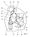
- Fig. 1 is a windshield wiper device 10 of a rear window wiper of a motor vehicle shown in a schematic representation.
- the windshield wiper device 10 comprises an electric motor 12 with a gear 14, which together form a drive element 16.
- the drive element 16 has a housing 18, the attachment arms 20 has. It can be made of plastic by injection molding or made of metal by die casting. At the ends of the fastening arms 20 fasteners 22 are formed with a U-shaped profile.
- a damping element 36 is inserted and fixedly connected to the fastening element 22.
- the damping element 36 after Fig. 1 has approximately centrally a bracket 38 with a slot 40 between two approximately parallel legs 44 and 46th
- the fastening element 22 is in a first mounting direction 30, which is approximately perpendicular to the plane of the Fig. 1 and axially parallel to the output shaft 28, inserted into the receiving opening 24, so that the opening of the slot 40th an edge of the mounting hole 24 is opposite. Thereafter, the fastener 22 in a second mounting direction 32, which in the embodiment according to Fig. 1 corresponds to a rotational movement about the output shaft 28 moves, wherein the slot 40 engages over the edge of the receiving opening, so that the windshield wiper device 10 is held by the slot 40 on the vehicle body 26 and simultaneously decoupled by the damping element 36 from the vibration of the vehicle body 26.
- the bracket 38 which has a harder surface than the damping element 36 slides easily over the body panel of the vehicle body 26. Furthermore, the assembly is facilitated by the fact that the slot 40 has a wedge-shaped extension 42 in the second mounting direction 32 at its opening , through which the edge of the receiving opening even with an inaccurate orientation of the fastener 22 securely enters the slot 40 and is held there with a bias.
- the windshield wiper device 10 can be fixed in the end position in the second mounting direction 32 in any manner, for example by a locking screw or a rivet. Conveniently, however, this is done by a detent 50 which is integrally formed on the one leg 44 of the bracket 38 and through an opening 48 in the opposite leg 46 engages ( Fig. 4 ). If the edge 80 of the receiving opening 24 is pushed through the extension 42 into the slot 40, it pushes back over a flat flank 52, the locking lug, wherein the damping element 36 yields accordingly. Reached the edge of the receiving opening 24 its end position, the detent 50 engages in a detent opening which is arranged offset in the second mounting direction 32 to the receiving opening 24. A steeper flank 54 on the second mounting direction 32 opposite side of the locking lug 50 ensures a secure fixation of the windshield wiper device 10th
- the bracket 38 has a second latching lug 56, which lies in the second mounting direction 32 behind the first latching lug 50. It is bounded by two steep flanks 60, 62 in the second mounting direction 32, which engage in an opening 58 of the opposite leg 46 and allow precise positioning of the windscreen wiper device 10 in a corresponding detent hole, not shown, of the vehicle body 26.
- the first detent 50 causes a rough pre-positioning
- the second detent 56 fixes the windshield wiper device 10 with little play in the second mounting direction 32.
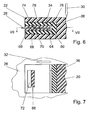
- the execution after 6 and 7 shows a damping element 36 with a recess 76 into which a holding element 64 is inserted from plastic.
- This can be in two parts, wherein the two parts are arranged to one another and firmly connected to the damping element 36, that they form a slot 78 between them, in which the sheet metal of the vehicle body 26 from the edge 80 of the receiving opening 24 can be inserted.
- the slot in the second mounting direction 32 can also expand in a funnel shape toward its opening.
- the component 64 has, on a surface facing the slot 78, a latching nose 66 which engages in the mounted state through a latching opening 72 in the body 26 in a recess 74 on the opposite side of the slot 78.
- the detent 66 has in the second mounting direction 32 has a front, flat edge 68 and in the opposite direction on a steep flank 70. If the edge 80 of the receiving opening 24 is pushed into the slot 78, the latching nose 66 is pushed back, wherein the damping element 36 yields. In the end position, when the latching nose 66 engages in the latching opening 72, it returns to its starting position and blocks the fastening element in the latching opening 72.
Landscapes
- Engineering & Computer Science (AREA)
- Mechanical Engineering (AREA)
- Body Structure For Vehicles (AREA)
- Connection Of Plates (AREA)
- Connection Of Motors, Electrical Generators, Mechanical Devices, And The Like (AREA)
- Vibration Prevention Devices (AREA)
Description
- Die Erfindung geht von einer Scheibenwischvorrichtung, insbesondere für ein Kraftfahrzeug, nach dem Oberbegriff des Anspruchs 1 aus.
- Es sind schon zahlreiche Scheibenwischvorrichtungen für Kraftfahrzeuge bekannt, die ein Antriebselement aufweisen, das an der Fahrzeugkarosserie befestigt ist. Typischerweise werden derartige Antriebselemente an der Fahrzeugkarosserie festgeschraubt, was jedoch sehr aufwändig ist und viele Teile, wie Schrauben, Schraubenmuttern und Unterlegscheiben usw. benötigt. Dies ist logistisch aufwändig und darüber hinaus komplex beim Einbau. Weiterhin ist aus der
DE 100 62 617 A1 eine Scheibenwischvorrichtung bekannt, die in das Kraftfahrzeug eingeklebt ist, wobei der Klebstoff dämpfende Eigenschaften aufweist. - Aus der
DE 198 33 404 A1 ist eine Scheibenwischanlage für Fahrzeuge, insbesondere Kraftfahrzeuge, bekannt, die eine verschraubungsfreie und damit einfach und schnell durchzuführende Montage ermöglicht. Hierzu weist die Scheibenwischanlage eine Tragkonstruktion für eine Antriebsvorrichtung auf. An der Tragkonstruktion ist eine Anzahl erster Befestigungselemente vorgesehen, die in eine erste Richtung von der Tragkonstruktion abragen. In eine zweite Richtung, die in einem Winkel zwischen 45 und 135 Grad zu der ersten Richtung verläuft, vorzugsweise in einem Winkel von 90 Grad, ragen eine Anzahl zweiter Befestigungselemente. Die Befestigungselemente sind als zylindrische Steckzapfen ausgebildet, die mit einem Ende mit der Tragkonstruktion verbunden sind und mit ihrem freien Ende in eine Aufnahmeöffnung eines gummielastischen Dämpfungselements gesteckt werden. Dieses ist in eine Montageöffnung der Fahrzeugkarosserie eingesetzt. Die Montageöffnung kann sich in einer abgewinkelten oder tief gezogenen Lasche befinden, die an der Fahrzeugkarosserie angeschweißt ist. Das freie Ende des Steckzapfens kann eine vorzugsweise konische Verdickung besitzen, um dasselbe in dem Dämpfungselement durch Verrasten festlegen zu können. Da die Montagerichtungen der ersten und zweiten Befestigungselemente unter einem Winkel verlaufen, ist es nicht ausgeschlossen, dass die Tragkonstruktion nach der Montage unter einer Spannung steht, die sich auf die angrenzenden Teile der Fahrzeugkarosserie überträgt. - Eine Scheibenwischvorrichtung gemäß Oberbegriff des Anspruchs 1 ist aus dem Dokument
WO-A-03/097419 - Das Dämpfungselement ist fest mit dem Befestigungselement verbunden. Es ist in einer ersten Montagerichtung in die Aufnahmeöffnung einsetzbar und übergreift durch eine Bewegung in eine zweite Montagerichtung quer zur ersten den Rand der Aufnahmeöffnung mit einem Schlitz. Dieser ist in einem Bauteil angeordnet, das eine relativ zum Dämpfungselement harte Oberfläche aufweist und mit dem Dämpfungselement fest verbunden ist. Auf Grund des geringen Reibwerts zwischen der harten Oberfläche des Schlitzes und der Fahrzeugkarosserie ergeben sich geringe Montagekräfte in der zweiten Montagerichtung, sodass die erfindungsgemäße Scheibenwischvorrichtung ohne großen Kraftaufwand montiert werden kann. Damit der Rand der Aufnahmeöffnung leicht in den Schlitz eingeführt werden kann, besitzt dieser an seiner Öffnung eine Erweiterung.
- Am Ende des zweiten Montagewegs muss die Scheibenwischvorrichtung in der Regel in der Endposition fixiert werden, damit sich das Befestigungselement mit dem Dämpfungselement nicht in entgegengesetzter Richtung wieder lösen kann. Zu diesem Zweck kann ein Arretierungselement, z.B. in Form eines Stifts oder einer Schraube, vorgesehen werden, das in der ersten Montagerichtung angeordnet ist und das Antriebselement mit der Fahrzeugkarosserie verbindet. Zweckmäßig weist es ebenfalls schwingungsdämpfende Maßnahmen auf. Dies bedeutet jedoch einen hohen Fertigungs- und Montageaufwand. Gemäß einer Ausgestaltung der Erfindung wird demgegenüber vorgeschlagen, dass der Bügel zwei im Wesentlichen parallel verlaufende Schenkel hat, die den Schlitz begrenzen, und von denen einer eine Rastnase aufweist, die in eine Öffnung des gegenüberliegenden Schenkels eingreift. Bei der Montage in der zweiten Montagerichtung wird die Rastnase am Rand der Aufnahmeöffnung durch das Karosserieblech zurückgedrückt und rastet bei Erreichen der Endposition in eine entsprechende Rastöffnung des Karosserieblechs ein. Um die Rastnase leicht zurückdrücken zu können, besitzt sie in der zweiten Montagerichtung eine flachere Flanke, während entgegen der zweiten Montagerichtung eine steilere Flanke der Rastnase dafür sorgt, dass die Endposition sicher verriegelt wird. Bei der Demontage kann die Rastnase von der flacheren Flanke aus mittels eines Schraubenziehers zurückgedrückt werden.
- Gemäß einer weiteren Ausgestaltung der Erfindung besitzt der Bügel eine zweite Rastnase, die in der zweiten Montagerichtung hinter der ersten Rastnase liegt und mit zwei steilen, quer zur zweiten Montagerichtung verlaufenden Flanken in eine Öffnung des gegenüberliegenden Schenkels eingreift. Bei der Montage rastet die zweite Rastnase ebenfalls in ein Rastloch der Fahrzeugkarosserie ein. Während durch die flache Flanke der ersten Rastnase beide Rastnasen außer Eingriff gebracht werden, und die erste Rastnase die Scheibenwischvorrichtung in der Endposition grob positioniert, ist durch die zweite Rastnase eine exaktere Positionierung der Scheibenwischvorrichtung relativ zu dem entsprechenden Rastloch in der Fahrzeugkarosserie möglich. Hierbei weist die zweite Rastnase im Längsschnitt des Bügels in vorteilhafter Weise eine m-förmige oder w-förmige Gestalt auf.
- Der Bügel, der zweckmäßigerweise aus Kunststoff oder Blech gefertigt ist, kann in einer Aussparung des Dämpfungselements eingepresst, eingeklebt, eingegossen oder einvulkanisiert oder formschlüssig gehalten sein. In vorteilhafter Weise ist der Schlitz des Bügels so auf die Dicke des Karosserieblechs oder einer Halterung abgestimmt, dass das Karosserieblech im montierten Zustand unter einer Vorspannung an den Innenseiten des Bügels anliegt.
- Bei einer weiteren Ausgestaltung ist in eine Aussparung des Dämpfungselements ein Halteelement aus Kunststoff eingesetzt, das einen Schlitz für die Aufnahme des Karosserieblechs besitzt, wobei eine Seite des Schlitzes eine Rastnase aufweist, die in eine Vertiefung auf der gegenüberliegenden Seite des Schlitzes ragt. Das Halteelement kann in der zweiten Montagerichtung im Bereich des Schlitzes geteilt und mit seinen äußeren Seiten an dem Dämpfungselement befestigt sein. Wird der Schlitz über den Rand der Aufnahmeöffnung geschoben, werden die beiden Teile auseinander gedrückt, wobei das Dämpfungselement elastisch nachgibt. Bei Erreichen der Endlage rastet die Rastnase in eine entsprechende Rastöffnung der Fahrzeugkarosserie ein. Auch hierbei ist es zweckmäßig, dass sich der Schlitz an seinem äußeren Ende in der zweiten Montagerichtung erweitert.
- Weitere Vorteile ergeben sich aus der folgenden Zeichnungsbeschreibung. In der Zeichnung sind Ausführungsbeispiele der Erfindung dargestellt. Die Zeichnung, die Beschreibung und die Ansprüche enthalten zahlreiche Merkmale in Kombination. Der Fachmann wird die Merkmale zweckmäßigerweise auch einzeln betrachten und zu sinnvollen weiteren Kombinationen zusammenfassen.
- Es zeigen:
- Fig. 1
- eine Antriebsvorrichtung einer erfindungsgemäßen Scheibenwischvorrichtung in einer schematischen Dar- stellung,
- Fig. 2
- einen Längsschnitt durch ein Befestigungselement ent- sprechend der Linie II-II in
Fig. 3 , - Fig. 3
- einen Schnitt entsprechend der Linie III-III in
Fig. 1 , - Fig. 4
- und
Fig. 5 eine Variante zuFig. 3 und - Fig. 6
- und
Fig. 7 eine Variante zuFig. 2 und Fig. 3 . - In
Fig. 1 ist eine Scheibenwischvorrichtung 10 eines Heckscheibenwischers eines Kraftfahrzeugs in einer schematischen Darstellung gezeigt. Natürlich ist die Erfindung in keiner Weise auf Heckscheibenwischer beschränkt. Sie kann problemlos auf Frontscheibenwischer angewendet werden. Die Scheibenwischvorrichtung 10 umfasst einen Elektromotor 12 mit einem Getriebe 14, die zusammen ein Antriebselement 16 bilden. Das Antriebselement 16 weist ein Gehäuse 18 auf, das Befestigungsarme 20 besitzt. Es kann aus Kunststoff im Spritzgussverfahren oder aus Metall im Druckgussverfahren hingestellt sein. An den Enden der Befestigungsarme 20 sind Befestigungselemente 22 mit einem u-förmigen Profil angeformt. - In der Aussparung 34 des u-förmigen Profils des Befestigungselements 22 ist ein Dämpfungselement 36 eingesetzt und mit dem Befestigungselement 22 fest verbunden. Das Dämpfungselement 36 nach
Fig. 1 besitzt etwa mittig einen Bügel 38 mit einem Schlitz 40 zwischen zwei annähernd parallel verlaufenden Schenkeln 44 und 46. - Das Befestigungselement 22 wird in einer ersten Montagerichtung 30, die etwa senkrecht zur Zeichenebene der
Fig. 1 und achsparallel zur Abtriebswelle 28 verläuft, in die Aufnahmeöffnung 24 eingesetzt, sodass die Öffnung des Schlitzes 40 einem Rand der Montageöffnung 24 gegenüberliegt. Danach wird das Befestigungselement 22 in einer zweiten Montagerichtung 32, die bei der Ausführung nachFig. 1 einer Drehbewegung um die Abtriebswelle 28 entspricht, bewegt, wobei der Schlitz 40 den Rand der Aufnahmeöffnung übergreift, sodass die Scheibenwischvorrichtung 10 durch den Schlitz 40 an der Fahrzeugkarosserie 26 gehalten wird und gleichzeitig durch das Dämpfungselement 36 schwingungstechnisch von der Fahrzeugkarosserie 26 entkoppelt ist. Bei der Montage gleitet der Bügel 38, der eine härtere Oberfläche hat als das Dämpfungselement 36, leicht über das Karosserieblech der Fahrzeugkarosserie 26. Ferner wird die Montage dadurch erleichtert, dass der Schlitz 40 in der zweiten Montagerichtung 32 an seiner Öffnung eine keilförmige Erweiterung 42 aufweist, durch die der Rand der Aufnahmeöffnung selbst bei einer ungenauen Ausrichtung des Befestigungselements 22 sicher in den Schlitz 40 gelangt und dort mit einer Vorspannung gehalten wird. - Die Scheibenwischvorrichtung 10 kann in der Endposition in der zweiten Montagerichtung 32 in beliebiger Weise fixiert werden, z.B. durch eine Arretierungsschraube oder einen Niet. Zweckmäßigerweise erfolgt dies jedoch durch eine Rastnase 50, die an dem einen Schenkel 44 des Bügels 38 angeformt ist und durch eine Öffnung 48 im gegenüberliegenden Schenkel 46 greift (
Fig. 4 ). Wird der Rand 80 der Aufnahmeöffnung 24 durch die Erweiterung 42 in den Schlitz 40 geschoben, drückt sie über eine flach verlaufende Flanke 52 die Rastnase zurück, wobei das Dämpfungselement 36 entsprechend nachgibt. Erreicht der Rand der Aufnahmeöffnung 24 seine Endposition, rastet die Rastnase 50 in eine Rastöffnung, die in der zweiten Montagerichtung 32 versetzt zur Aufnahmeöffnung 24 angeordnet ist. Eine steilere Flanke 54 auf der der zweiten Montagerichtung 32 entgegengesetzten Seite der Rastnase 50 gewährleistet eine sichere Fixierung der Scheibenwischvorrichtung 10. - Bei der Ausführung nach
Fig. 5 besitzt der Bügel 38 eine zweite Rastnase 56, die in der zweiten Montagerichtung 32 hinter der ersten Rastnase 50 liegt. Sie wird von zwei steilen Flanken 60, 62 in der zweiten Montagerichtung 32 begrenzt, die in eine Öffnung 58 des gegenüberliegenden Schenkels 46 eingreifen und eine präzise Positionierung der Scheibenwischvorrichtung 10 in einem entsprechenden, nicht dargestellten Rastloch der Fahrzeugkarosserie 26 ermöglichen. Dabei bewirkt die erste Rastnase 50 eine grobe Vorpositionierung, während die zweite Rastnase 56 die Scheibenwischvorrichtung 10 mit geringem Spiel in der zweiten Montagerichtung 32 fixiert. - Die Ausführung nach
Fig. 6 und 7 zeigt ein Dämpfungselement 36 mit einer Aussparung 76, in die ein Halteelement 64 aus Kunststoff eingesetzt ist. Dieses kann zweiteilig sein, wobei die beiden Teile so zueinander angeordnet und mit dem Dämpfungselement 36 fest verbunden sind, dass sie zwischen sich einen Schlitz 78 bilden, in den das Blech der Fahrzeugkarosserie 26 vom Rand 80 der Aufnahmeöffnung 24 eingeschoben werden kann. Dabei kann sich der Schlitz in der zweiten Montagerichtung 32 zu seiner Öffnung hin ebenfalls trichterförmig erweitern. Das Bauteil 64 besitzt an einer zum Schlitz 78 hin weisenden Fläche eine Rastnase 66, die im montierten Zustand durch eine Rastöffnung 72 in der Karosserie 26 in eine Vertiefung 74 auf der gegenüberliegenden Seite des Schlitzes 78 eingreift. Die Rastnase 66 weist in der zweiten Montagerichtung 32 eine vordere, flach verlaufende Flanke 68 und in der entgegengesetzten Richtung eine steil verlaufende Flanke 70 auf. Wird der Rand 80 der Aufnahmeöffnung 24 in den Schlitz 78 geschoben, wird die Rastnase 66 zurückgeschoben, wobei das Dämpfungselement 36 nachgibt. In der Endposition, wenn die Rastnase 66 in die Rastöffnung 72 einrastet, nimmt sie wieder ihre Ausgangsposition ein und blockiert das Befestigungselement in der Rastöffung 72.
Claims (9)
- Scheibenwischvorrichtung (10), insbesondere für ein Kraftfahrzeug, mit mindestens einem an der Fahrzeugkarosserie (26) zu befestigenden Antriebselement (16) mit einer Abtriebswelle (28) und mindestens zwei Befestigungselementen (22), die in Aufnahmeöffnungen (24) an der Fahrzeugkarosserie (26) einzugreifen vermögen und jeweils zumindest ein Dämpfungselement (36) zur Dämpfung mechanischer Schwingungen aufweisen, und das Dämpfungselement (36) fest mit dem Befestigungselement (22) verbunden und in einer ersten Montagerichtung (30) in die Aufnahmeöffnungen (24) einsetzbar ist dadurch gekennzeichnet, dass durch eine Bewegung in eine zweite Montagerichtung (32) quer zur ersten den Rand (80) der Aufnahmeöffnung (24) mit einem Schlitz (40) übergreift, wobei der Schlitz (40) in einem Bauteil (38, 64) angeordnet ist, das eine relativ zum Dämpfungselement (36) harte Oberfläche aufweist und mit dem Dämpfungselement (36) fest verbunden ist.
- Scheibenwischvorrichtung nach Anspruch 1, dadurch gekennzeichnet, dass der Schlitz (40) von einem Bügel (38) gebildet wird, in der zweiten Montagerichtung (32) offen ist und an seiner Öffnung eine Erweiterung (42) besitzt.
- Scheibenwischvorrichtung (10) nach Anspruch 2, dadurch gekennzeichnet, dass der Bügel (38) zwei im Wesentlichen parallel verlaufende Schenkel (44, 46) hat, die den Schlitz (40) begrenzen und von denen einer (44) eine Rastnase (50) aufweist, die in eine Öffnung (48) des gegenüberliegenden Schenkels (46) eingreift. (Fig. 4)
- Scheibenwischvorrichtung (10) nach Anspruch 3, dadurch gekennzeichnet, dass die Rastnase (50) in der zweiten Montagerichtung (32) eine flachere Flanke (52) und entgegen der zweiten Montagerichtung (32) eine steilere Flanke (54) besitzt.
- Scheibenwischvorrichtung (10) nach Anspruch 4, dadurch gekennzeichnet, dass der Bügel (38) eine zweite Rastnase (56) besitzt, die in der zweiten Montagerichtung (32) hinter der ersten Rastnase (50) liegt und mit zwei steilen, quer zur zweiten Montagerichtung (32) verlaufenden Flanken (60, 62) in eine Öffnung (58) des gegenüberliegenden Schenkels (46) eingreift. (Fig. 5)
- Scheibenwischvorrichtung (10) nach Anspruch 5, dadurch gekennzeichnet, dass die zweite Rastnase (56) im Längsschnitt des Bügels (38) eine m-förmige oder w-förmige Gestalt hat.
- Scheibenwischvorrichtung (10) nach einem der vorhergehenden Ansprüche, dadurch gekennzeichnet, dass der Bügel (38) aus Kunststoff oder Blech gefertigt ist.
- Scheibenwischvorrichtung (10) nach Anspruch 1, dadurch gekennzeichnet, dass in einer Aussparung (76) des Dämpfungselements (36) ein Halteelement (64) aus Kunststoff eingesetzt ist, das einen Schlitz (78) für die Aufnahme des Karosserieblechs besitzt, wobei eine Seite des Schlitzes (78) eine Rastnase (66) aufweist, die in eine Vertiefung (74) auf der gegenüberliegenden Seite des Schlitzes (78) ragt.
- Scheibenwischvorrichtung (10) nach einem der vorhergehenden Ansprüche, dadurch gekennzeichnet, dass die zweite Montagerichtung (32) eine Drehrichtung um die Antriebswelle (28) oder um eine zur Antriebswelle (28) parallele Achse ist und die Rastnase (50, 56, 66) sich radial zur Antriebswelle (28) bzw. zur parallelen Achse erstreckt.
Applications Claiming Priority (2)
| Application Number | Priority Date | Filing Date | Title |
|---|---|---|---|
| DE102004016914A DE102004016914A1 (de) | 2004-04-06 | 2004-04-06 | Scheibenwischvorrichtung, insbesondere für ein Kraftfahrzeug |
| PCT/EP2005/050635 WO2005097564A1 (de) | 2004-04-06 | 2005-02-14 | Scheibenwischvorrichtung, insbesondere für ein kraftfahrzeug |
Publications (2)
| Publication Number | Publication Date |
|---|---|
| EP1735193A1 EP1735193A1 (de) | 2006-12-27 |
| EP1735193B1 true EP1735193B1 (de) | 2009-06-03 |
Family
ID=34961204
Family Applications (1)
| Application Number | Title | Priority Date | Filing Date |
|---|---|---|---|
| EP05716687A Expired - Lifetime EP1735193B1 (de) | 2004-04-06 | 2005-02-14 | Scheibenwischvorrichtung, insbesondere für ein kraftfahrzeug |
Country Status (10)
| Country | Link |
|---|---|
| US (1) | US7600803B2 (de) |
| EP (1) | EP1735193B1 (de) |
| JP (1) | JP4518509B2 (de) |
| KR (1) | KR101081763B1 (de) |
| CN (1) | CN100537312C (de) |
| BR (1) | BRPI0509619A (de) |
| DE (2) | DE102004016914A1 (de) |
| ES (1) | ES2327246T3 (de) |
| RU (1) | RU2370383C2 (de) |
| WO (1) | WO2005097564A1 (de) |
Families Citing this family (10)
| Publication number | Priority date | Publication date | Assignee | Title |
|---|---|---|---|---|
| DE102007033683A1 (de) * | 2007-07-19 | 2009-01-22 | Robert Bosch Gmbh | Dämpfungselement |
| DE102007040504A1 (de) * | 2007-08-28 | 2009-03-05 | Robert Bosch Gmbh | Wischanlage mit einem Wischantrieb zum Antrieb eines Wischgestänges |
| DE102007043249A1 (de) | 2007-09-11 | 2009-03-12 | Robert Bosch Gmbh | Dämpfungselement |
| KR101405606B1 (ko) * | 2008-09-24 | 2014-06-10 | 기아자동차주식회사 | 차량의 와이퍼모터 마운팅 장치 |
| DE102010063143A1 (de) * | 2010-12-15 | 2012-06-21 | Robert Bosch Gmbh | Scheibenwischvorrichtung für ein Kraftfahrzeug |
| JP5852438B2 (ja) | 2011-03-09 | 2016-02-03 | アスモ株式会社 | アームヘッド |
| US9956999B2 (en) * | 2011-07-22 | 2018-05-01 | Magna International Inc. | Windshield wiper module |
| KR101156740B1 (ko) * | 2012-04-20 | 2012-06-14 | 동양기전 주식회사 | 차량용 와이퍼 장치 |
| WO2014114333A1 (de) * | 2013-01-24 | 2014-07-31 | Robert Bosch Gmbh | Antriebseinrichtung für einen wischerarm |
| DE102014215831B4 (de) * | 2014-08-11 | 2025-01-23 | Robert Bosch Gmbh | Scheibenwischvorrichtung |
Family Cites Families (22)
| Publication number | Priority date | Publication date | Assignee | Title |
|---|---|---|---|---|
| DE2431110A1 (de) * | 1974-06-28 | 1976-01-15 | Gerd Homola | Begrenzungssimmering |
| US5274875A (en) * | 1993-01-25 | 1994-01-04 | Chou Liao Ter | Displaceable rear windshield wiper incorporating trunk lid interaction and a rear brake light |
| US5949206A (en) * | 1995-04-28 | 1999-09-07 | Ut Automotive Dearborn, Inc. | Multi-functional apparatus employing an intermittent motion mechanism |
| DE19735818C2 (de) * | 1997-08-18 | 1999-10-21 | Daimler Chrysler Ag | Befestigungsvorrichtung für eine Scheibenwischeranlage eines Kraftfahrzeuges |
| FR2770880B1 (fr) * | 1997-11-10 | 2000-01-07 | Peugeot | Ensemble pour le positionnement, le centrage et le maintien en service d'une piece mecanique |
| FR2775456B1 (fr) * | 1998-02-27 | 2000-05-12 | Valeo Systemes Dessuyage | Dispositif d'essuyage pour vehicule automobile comportant une platine de fixation susceptible de s'effacer en cas de choc, et platine appartenant a un tel dispositif |
| DE19833404A1 (de) * | 1998-07-24 | 2000-01-27 | Itt Mfg Enterprises Inc | Scheibenwischeranlage für Fahrzeuge |
| CZ20022071A3 (cs) * | 2000-10-23 | 2003-01-15 | Robert Bosch Gmbh | Upevnění stěracího zařízení na karosérii vozidla |
| DE10062617A1 (de) | 2000-10-23 | 2002-05-02 | Bosch Gmbh Robert | Befestigung für eine Scheibenwischeranlage |
| DE10143610A1 (de) * | 2001-09-06 | 2003-04-10 | Bosch Gmbh Robert | Scheibenwischeranlage |
| DE10155269A1 (de) * | 2001-11-09 | 2003-05-22 | Valeo Auto Electric Gmbh | Wischanlage für eine Scheibe eines Kraftfahrzeugs |
| DE10205019A1 (de) * | 2002-02-07 | 2003-08-21 | Bosch Gmbh Robert | Scheibenwischvorrichtung |
| FR2839691B1 (fr) | 2002-05-17 | 2006-04-28 | Valeo Systemes Dessuyage | Agencement pour le positionnement et la fixation des moyens d'entrainement d'un mecanisme d'essuie-glace |
| FR2842154B1 (fr) * | 2002-07-11 | 2004-09-10 | Valeo Systemes Dessuyage | "agencement pour le montage d'un mecanisme d'essuie-glace sur un panneau vitre" |
| US7144065B2 (en) * | 2002-12-30 | 2006-12-05 | Valeo Electrical Systems, Inc. | Vehicle liftgate with accessory component module |
| DE10301900A1 (de) * | 2003-01-17 | 2004-07-29 | Robert Bosch Gmbh | Scheibenwischvorrichtung, insbesondere für ein Kraftfahrzeug |
| FR2853606B1 (fr) * | 2003-04-11 | 2006-04-21 | Valeo Systemes Dessuyage | Procede et agencement pour l'assemblage par succession de deux mouvements selon une direction longitudinale |
| DE102004005067A1 (de) * | 2004-02-02 | 2005-08-18 | Robert Bosch Gmbh | Scheibenwischvorrichtung, insbesondere für ein Kraftfahrzeug |
| FR2865981B1 (fr) * | 2004-02-06 | 2006-04-21 | Valeo Systemes Dessuyage | Moto-reducteur notamment pour mecanisme d'essuie-glace de vehicule automobile |
| FR2868375B1 (fr) * | 2004-04-01 | 2006-06-02 | Valeo Systemes Dessuyage | Agencement pour la fixation d'un mecanisme d'essuyage |
| DE102005048341A1 (de) * | 2005-06-10 | 2006-12-14 | Robert Bosch Gmbh | Scheibenwischvorrichtung |
| CA2591356A1 (en) * | 2006-07-19 | 2008-01-19 | Inventio Ag | Mounting slide insert for use in a guide shoe of a lift installation, method for placing a lift installation in operation, and corresponding mounting set and an associated lift installation |
-
2004
- 2004-04-06 DE DE102004016914A patent/DE102004016914A1/de not_active Withdrawn
-
2005
- 2005-02-14 EP EP05716687A patent/EP1735193B1/de not_active Expired - Lifetime
- 2005-02-14 DE DE502005007410T patent/DE502005007410D1/de not_active Expired - Lifetime
- 2005-02-14 CN CNB2005800120905A patent/CN100537312C/zh not_active Expired - Fee Related
- 2005-02-14 WO PCT/EP2005/050635 patent/WO2005097564A1/de not_active Ceased
- 2005-02-14 JP JP2007506750A patent/JP4518509B2/ja not_active Expired - Fee Related
- 2005-02-14 BR BRPI0509619-7A patent/BRPI0509619A/pt not_active Application Discontinuation
- 2005-02-14 ES ES05716687T patent/ES2327246T3/es not_active Expired - Lifetime
- 2005-02-14 RU RU2006139008/11A patent/RU2370383C2/ru not_active IP Right Cessation
- 2005-02-14 KR KR1020067020856A patent/KR101081763B1/ko not_active Expired - Fee Related
- 2005-02-14 US US11/547,618 patent/US7600803B2/en not_active Expired - Fee Related
Also Published As
| Publication number | Publication date |
|---|---|
| DE102004016914A1 (de) | 2005-10-20 |
| RU2370383C2 (ru) | 2009-10-20 |
| KR20070020437A (ko) | 2007-02-21 |
| CN1942351A (zh) | 2007-04-04 |
| JP4518509B2 (ja) | 2010-08-04 |
| DE502005007410D1 (de) | 2009-07-16 |
| ES2327246T3 (es) | 2009-10-27 |
| CN100537312C (zh) | 2009-09-09 |
| WO2005097564A1 (de) | 2005-10-20 |
| EP1735193A1 (de) | 2006-12-27 |
| BRPI0509619A (pt) | 2007-09-18 |
| US7600803B2 (en) | 2009-10-13 |
| JP2007531664A (ja) | 2007-11-08 |
| US20070209137A1 (en) | 2007-09-13 |
| RU2006139008A (ru) | 2008-09-20 |
| KR101081763B1 (ko) | 2011-11-10 |
Similar Documents
| Publication | Publication Date | Title |
|---|---|---|
| EP1735194B1 (de) | Scheibenwischvorrichtung, insbesondere für ein kraftfahrzeug | |
| EP1713669B1 (de) | Scheibenwischvorrichtung, insbesondere für ein kraftfahrzeug | |
| DE10327858A1 (de) | Scheibenwischvorrichtung, insbesondere für ein Kraftfahrzeug | |
| EP2459425B1 (de) | Baugruppe bestehend aus einem ausgleichsbehälter und einem hauptzylinder für eine hydraulische kraftfahrzeugbremsanlage | |
| EP1735193B1 (de) | Scheibenwischvorrichtung, insbesondere für ein kraftfahrzeug | |
| WO2007144221A1 (de) | Scheibenwischvorrichtung, insbesondere für ein kraftfahrzeug | |
| DE102009013988A1 (de) | Spritzwand mit Kupplungsgeberzylinder | |
| EP1144231A2 (de) | Scheibenwischeranlage | |
| DE102006013696A1 (de) | Scheibenwischerantriebsanordnung | |
| DE10325736A1 (de) | Scheibenwischervorrichtung, insbesondere für ein Kraftfahrzeug | |
| EP1587721B1 (de) | Scheibenwischvorrichtung, insbesondere für ein kraftfahrzeug | |
| DE102015205061A1 (de) | Motorpumpenaggregat mit einer Membraneinheit | |
| EP2006171A2 (de) | Scheibenwischerantriebsanordnung | |
| EP1375270B1 (de) | Scheibenwischvorrichtung, insbesondere für ein Kraftfahrzeug | |
| DE102009045338B4 (de) | Scheibenwischvorrichtung | |
| DE102008033831B4 (de) | Befestigungsanordnung für eine Scheibenwischvorrichtung an einem Fahrzeug | |
| EP2072356B1 (de) | Wischanlage für ein Kraftfahrzeug | |
| DE102008016390B4 (de) | Filtereinrichtung | |
| DE102014103541A1 (de) | Baugruppe für ein Kraftfahrzeug und Verfahren zum Verbinden eines Karosserieteils mit einem Spoiler | |
| DE102019206665A1 (de) | Scheibenwischantrieb | |
| EP2429868B1 (de) | Befestigungsanordnung | |
| EP2744689A1 (de) | Scheibenwischerlager-rohrverbindung | |
| DE102008059325B4 (de) | Stoßfängeranordnung | |
| EP1676761A1 (de) | Scheibenwischvorrichtung | |
| DE102006009687B4 (de) | Halterung einer Wischeranlage eines Kraftfahrzeuges |
Legal Events
| Date | Code | Title | Description |
|---|---|---|---|
| PUAI | Public reference made under article 153(3) epc to a published international application that has entered the european phase |
Free format text: ORIGINAL CODE: 0009012 |
|
| 17P | Request for examination filed |
Effective date: 20061106 |
|
| AK | Designated contracting states |
Kind code of ref document: A1 Designated state(s): CZ DE ES FR IT |
|
| DAX | Request for extension of the european patent (deleted) | ||
| RBV | Designated contracting states (corrected) |
Designated state(s): CZ DE ES FR IT |
|
| GRAP | Despatch of communication of intention to grant a patent |
Free format text: ORIGINAL CODE: EPIDOSNIGR1 |
|
| RIN1 | Information on inventor provided before grant (corrected) |
Inventor name: GEUBEL, PAUL Inventor name: LIPPS, VERENA |
|
| GRAS | Grant fee paid |
Free format text: ORIGINAL CODE: EPIDOSNIGR3 |
|
| GRAA | (expected) grant |
Free format text: ORIGINAL CODE: 0009210 |
|
| AK | Designated contracting states |
Kind code of ref document: B1 Designated state(s): CZ DE ES FR IT |
|
| REF | Corresponds to: |
Ref document number: 502005007410 Country of ref document: DE Date of ref document: 20090716 Kind code of ref document: P |
|
| REG | Reference to a national code |
Ref country code: ES Ref legal event code: FG2A Ref document number: 2327246 Country of ref document: ES Kind code of ref document: T3 |
|
| PLBE | No opposition filed within time limit |
Free format text: ORIGINAL CODE: 0009261 |
|
| STAA | Information on the status of an ep patent application or granted ep patent |
Free format text: STATUS: NO OPPOSITION FILED WITHIN TIME LIMIT |
|
| 26N | No opposition filed |
Effective date: 20100304 |
|
| REG | Reference to a national code |
Ref country code: FR Ref legal event code: PLFP Year of fee payment: 12 |
|
| REG | Reference to a national code |
Ref country code: FR Ref legal event code: PLFP Year of fee payment: 13 |
|
| PGFP | Annual fee paid to national office [announced via postgrant information from national office to epo] |
Ref country code: FR Payment date: 20170220 Year of fee payment: 13 |
|
| PGFP | Annual fee paid to national office [announced via postgrant information from national office to epo] |
Ref country code: CZ Payment date: 20170207 Year of fee payment: 13 |
|
| PGFP | Annual fee paid to national office [announced via postgrant information from national office to epo] |
Ref country code: IT Payment date: 20170217 Year of fee payment: 13 Ref country code: ES Payment date: 20170220 Year of fee payment: 13 |
|
| PGFP | Annual fee paid to national office [announced via postgrant information from national office to epo] |
Ref country code: DE Payment date: 20170427 Year of fee payment: 13 |
|
| REG | Reference to a national code |
Ref country code: DE Ref legal event code: R119 Ref document number: 502005007410 Country of ref document: DE |
|
| PG25 | Lapsed in a contracting state [announced via postgrant information from national office to epo] |
Ref country code: CZ Free format text: LAPSE BECAUSE OF NON-PAYMENT OF DUE FEES Effective date: 20180214 |
|
| REG | Reference to a national code |
Ref country code: FR Ref legal event code: ST Effective date: 20181031 |
|
| PG25 | Lapsed in a contracting state [announced via postgrant information from national office to epo] |
Ref country code: DE Free format text: LAPSE BECAUSE OF NON-PAYMENT OF DUE FEES Effective date: 20180901 |
|
| PG25 | Lapsed in a contracting state [announced via postgrant information from national office to epo] |
Ref country code: IT Free format text: LAPSE BECAUSE OF NON-PAYMENT OF DUE FEES Effective date: 20180214 Ref country code: FR Free format text: LAPSE BECAUSE OF NON-PAYMENT OF DUE FEES Effective date: 20180228 |
|
| REG | Reference to a national code |
Ref country code: ES Ref legal event code: FD2A Effective date: 20190801 |
|
| PG25 | Lapsed in a contracting state [announced via postgrant information from national office to epo] |
Ref country code: ES Free format text: LAPSE BECAUSE OF NON-PAYMENT OF DUE FEES Effective date: 20180215 |