EP1735487B1 - Vorrichtung und ein verfahren zum präparationsauftrag auf fäden - Google Patents
Vorrichtung und ein verfahren zum präparationsauftrag auf fäden Download PDFInfo
- Publication number
- EP1735487B1 EP1735487B1 EP05731712A EP05731712A EP1735487B1 EP 1735487 B1 EP1735487 B1 EP 1735487B1 EP 05731712 A EP05731712 A EP 05731712A EP 05731712 A EP05731712 A EP 05731712A EP 1735487 B1 EP1735487 B1 EP 1735487B1
- Authority
- EP
- European Patent Office
- Prior art keywords
- housing
- preparation
- thread
- foregoing
- oil
- Prior art date
- Legal status (The legal status is an assumption and is not a legal conclusion. Google has not performed a legal analysis and makes no representation as to the accuracy of the status listed.)
- Expired - Lifetime
Links
- 238000002360 preparation method Methods 0.000 title claims abstract description 110
- 238000000034 method Methods 0.000 title claims abstract description 15
- 239000012530 fluid Substances 0.000 claims abstract description 14
- 238000009987 spinning Methods 0.000 claims description 3
- 239000000919 ceramic Substances 0.000 claims description 2
- 239000000463 material Substances 0.000 claims description 2
- 230000001105 regulatory effect Effects 0.000 claims description 2
- 238000004064 recycling Methods 0.000 claims 1
- 239000003595 mist Substances 0.000 description 6
- 239000007921 spray Substances 0.000 description 6
- 238000007789 sealing Methods 0.000 description 5
- 239000007788 liquid Substances 0.000 description 4
- 239000003795 chemical substances by application Substances 0.000 description 3
- 238000003780 insertion Methods 0.000 description 3
- 230000037431 insertion Effects 0.000 description 3
- 238000011109 contamination Methods 0.000 description 2
- 241001589086 Bellapiscis medius Species 0.000 description 1
- 230000000694 effects Effects 0.000 description 1
- 238000005516 engineering process Methods 0.000 description 1
- 238000004519 manufacturing process Methods 0.000 description 1
- 239000000203 mixture Substances 0.000 description 1
- 238000002663 nebulization Methods 0.000 description 1
- 238000000926 separation method Methods 0.000 description 1
- 239000010913 used oil Substances 0.000 description 1
- 238000009736 wetting Methods 0.000 description 1
Images



Classifications
-
- D—TEXTILES; PAPER
- D02—YARNS; MECHANICAL FINISHING OF YARNS OR ROPES; WARPING OR BEAMING
- D02G—CRIMPING OR CURLING FIBRES, FILAMENTS, THREADS, OR YARNS; YARNS OR THREADS
- D02G1/00—Producing crimped or curled fibres, filaments, yarns, or threads, giving them latent characteristics
- D02G1/16—Producing crimped or curled fibres, filaments, yarns, or threads, giving them latent characteristics using jets or streams of turbulent gases, e.g. air, steam
- D02G1/164—Producing crimped or curled fibres, filaments, yarns, or threads, giving them latent characteristics using jets or streams of turbulent gases, e.g. air, steam in the presence of a liquid, e.g. a crimp finish
-
- D—TEXTILES; PAPER
- D01—NATURAL OR MAN-MADE THREADS OR FIBRES; SPINNING
- D01D—MECHANICAL METHODS OR APPARATUS IN THE MANUFACTURE OF ARTIFICIAL FILAMENTS, THREADS, FIBRES, BRISTLES OR RIBBONS
- D01D5/00—Formation of filaments, threads, or the like
- D01D5/08—Melt spinning methods
- D01D5/096—Humidity control, or oiling, of filaments, threads or the like, leaving the spinnerettes
-
- D—TEXTILES; PAPER
- D02—YARNS; MECHANICAL FINISHING OF YARNS OR ROPES; WARPING OR BEAMING
- D02G—CRIMPING OR CURLING FIBRES, FILAMENTS, THREADS, OR YARNS; YARNS OR THREADS
- D02G1/00—Producing crimped or curled fibres, filaments, yarns, or threads, giving them latent characteristics
- D02G1/16—Producing crimped or curled fibres, filaments, yarns, or threads, giving them latent characteristics using jets or streams of turbulent gases, e.g. air, steam
- D02G1/161—Producing crimped or curled fibres, filaments, yarns, or threads, giving them latent characteristics using jets or streams of turbulent gases, e.g. air, steam yarn crimping air jets
-
- D—TEXTILES; PAPER
- D06—TREATMENT OF TEXTILES OR THE LIKE; LAUNDERING; FLEXIBLE MATERIALS NOT OTHERWISE PROVIDED FOR
- D06B—TREATING TEXTILE MATERIALS USING LIQUIDS, GASES OR VAPOURS
- D06B1/00—Applying liquids, gases or vapours onto textile materials to effect treatment, e.g. washing, dyeing, bleaching, sizing or impregnating
- D06B1/08—Applying liquids, gases or vapours onto textile materials to effect treatment, e.g. washing, dyeing, bleaching, sizing or impregnating from outlets being in, or almost in, contact with the textile material
-
- D—TEXTILES; PAPER
- D06—TREATMENT OF TEXTILES OR THE LIKE; LAUNDERING; FLEXIBLE MATERIALS NOT OTHERWISE PROVIDED FOR
- D06B—TREATING TEXTILE MATERIALS USING LIQUIDS, GASES OR VAPOURS
- D06B23/00—Component parts, details, or accessories of apparatus or machines, specially adapted for the treating of textile materials, not restricted to a particular kind of apparatus, provided for in groups D06B1/00 - D06B21/00
- D06B23/14—Containers, e.g. vats
- D06B23/18—Sealing arrangements
Definitions
- the invention relates to a device and a method for preparation of a preparation on threads with a housing which has an inlet opening and an outlet opening for a thread and a preparation device arranged in the housing.
- preparations there are several known methods and ways to apply preparations to a thread or yarn.
- the order is made e.g. by passing the yarn over rollers rotating through an oil bath and moistening with oil.
- Another possibility is that the yarn passes over a preparation pin.
- the pin has a bore over which preparation oil is fed and the yarn receives the oil application via contact with the pin. Then there are procedures in which the preparation is applied by oil spray or a combination of swirling with oil supply.
- the DE 102 05 005 A1 describes a preparation device in which the preparation is applied by a spray mist.
- the metered dosage of the yarn is achieved by means of a screen which shields part of the spray jet from the yarn.
- the excess preparation is collected via a catch plate in the spray box and returned via a drain in the oil circuit.
- the disadvantage of this design is that more oil is needed than is circulated and not all of the excess oil mist is collected through the catch plate and thus escapes a portion of the oil mist through the inlet and outlet ports of the spray box.
- Another disadvantage is that the oil application with the help of the spray is only superficial and the oil is not completely mixed with the yarn filaments.
- the yarn can not absorb enough preparation by means of a superficial preparation application and disturbances occur in the process or in the subsequent further processing process.
- the object of the invention is to provide a preparation device in which the yarn precisely metered the yarn preparation is fed and mixed with the yarn and to perform the device so that the excess preparation or the oil mist can not escape from the device, but dissipated for reuse becomes.
- the invention relates to a device for preparation application to threads. It has a housing which has an inlet opening and an outlet opening for the thread.
- a preparation device is arranged in the housing.
- the housing is divided at the inlet and outlet opening, so that the thread can be easily inserted into the housing. Due to the division of the housing, it is avoided that the thread is threaded through a small opening of the housing, guided through the housing and has to be led out of the housing again at the end of the housing. This considerable work is no longer required with the present invention, since the housing is divided in the region of the inlet and outlet and can be opened here. In the open state of the housing, the thread is inserted transversely to the passage direction in the housing and the housing then closed again. The thread is thus ready for a preparation, in particular with preparation oil. Due to the division of the housing at the inlet and outlet opening, the housing can be opened by a pivoting movement or a linear movement in the thread passage direction.
- the housing division and / or the inlet and outlet openings are sealed or act.
- the seal ensures that the spin finish remains within the housing.
- the fluid can also be collected within the housing and fed to the preparation device or to a collecting container.
- the preparation device is a swirling device and an oil device.
- a uniform application of the preparation, in particular oil causes the thread.
- the swirling device the oil is atomized evenly and thereby can evenly wet the thread.
- the preparation device for inserting the thread has a divided yarn channel, it is very easy to insert the thread into the preparation device by opening the yarn channel in the preparation device. After the thread is in the divided yarn channel, the preparation device is closed again and is ready for the preparation of the thread.
- a labyrinth seal for the sealing of the inlet and outlet device, inter alia, a labyrinth seal, an opening closely surrounding the thread, negative pressure in the housing and / or a seal pressurized with compressed air at the inlet and outlet openings are advantageous.
- the labyrinth seal is as well as the thread closely enclosing opening of the inlet or outlet opening purely constructive to solve. Often, however, it is sufficient if the negative pressure in the housing, which arises, for example, by the suction of the reusable preparation liquid, already achieved a sufficient seal.
- a compressed air-loaded seal is arranged at the respective opening. If in each case compressed air is injected at the inlet and outlet opening, a kind of air curtain arises here, which largely prevents the passage of the preparation preparation.
- pin oiler It is particularly simple and inexpensive if a pin oiler is used as an oil device.
- the known per se pin lubricator is disposed within the housing and causes the passing past the pen oiler thread is uniformly and sufficiently prepared.
- the reusable preparation liquid can be collected in a particularly advantageous manner and fed to an oil container assigned to the housing or else to a used oil container.
- the housing is assigned a regulator.
- the amount of oil supplied to the yarn or the preparation device can be adjusted via the rule.
- the preparation application can be adjusted to the specific thread or the desired amount of the preparation application.
- the yarn channel is radially closed with a spring-loaded baffle plate.
- the spring ensures that the baffle plate is always pressed against a bearing surface and only the yarn channel for the passage of the thread remains open. In particular, a lateral deflection of the thread out of the yarn channel is thereby avoided.
- the thread is specifically exposed to the thread acting in the yarn channel Reparationsmit tel A consistent preparation without the use of an unnecessary amount of preparation agent is thereby ensured.
- parts of the housing and of the preparation device which come into contact with the thread are made of wear-resistant material, in particular ceramic.
- the preparation device and, for example, the inlet and outlet openings of the housing are thus protected against wear and ensure a long use of the housing.
- the device according to the invention can be used not only for the treatment of a single thread, but also for the treatment of a group of threads.
- the housing is equipped with several preparation devices.
- the simultaneous insertion of a plurality of threads in a single open housing is thereby particularly facilitated
- the production of a single housing for a plurality of threads is less expensive than if individual threads would be prepared separately.
- the housing is opened to insert a thread in the direction of yarn passage and the housing division and / or the Inlet and outlet ports sealed when closing the housing.
- the thread is prepared very quickly for preparation Due to the tight closing of the housing after inserting the thread, the housing is largely completed, so that no spin finish emerges from the housing.
- a preparation of the thread is thereby made both very reliable and without loss of spin finish very cost
- the housing is divided at the inlet and outlet opening, it is particularly easy to insert the thread. Threading in eyelets is thereby avoided.
- the air and / or preparation fluid feed into the housing is interrupted, it is ensured that the preparation fluid does not escape from the housing. Pollution of the surroundings of the housing is avoided.
- a control of the supply of air and / or preparation fluid can be used to advantageously bring the air and / or preparation fluid supply into operation automatically when the housing is closed.
- the restart after a yarn breakage can be done very easily by the housing is opened, wherein automatically switches off the air and / or preparation liquid supply, then the thread is inserted into the housing and in the preparation device and finally the housing closed again and the air and / or preparation liquid supply is put into operation again.
- the re-threading of the thread is particularly easy and fast if, together with the opening of the housing, the preparation device is also opened. Only one handgrip is required to open and close the housing and the preparation device.
- inlet and outlet ports are sealed with compressed air, then a very dense housing with respect to the preparation medium is obtained, in which the inlet and outlet openings can be made relatively large, so that the thread can be moved through the housing without obstruction.
- FIG. 1 shows a complete inventive device for preparation application.
- a thread 1 passes through a thread inlet opening 3 of a housing 2, is wetted in the preparation device 4, here a S directedöler, with oil as a spin finish and then vortexed in a swirling device 5.
- the turbulence is a uniform mixing and wetting of the individual filaments of the thread 1 with the oil.
- the thread 1 emerges from the housing 2 at the other end through an outlet opening 6.
- the oil supply from an oil reservoir 7 is controlled by an oil regulator 8.
- the yarn 1 is tangent to the preparation device 4 and is supplied with oil flowing from a supply bore of the preparation device 4.
- the execution of the preparation device 4 can according to the current state technology, as is well known.
- In the thread passage direction after the preparation device 4 is the swirling device 5.
- the thread 1 passes through a closed yarn channel 9 of the swirling device 5 and is acted upon via a compressed air channel 10 with compressed air.
- the compressed air supply is regulated by a pressure regulator 11.
- the amount of air is determined by the Verwirbelungstik and the shape of the compressed air channel 10.
- the thread inlet opening 3 and the thread outlet opening 6 are designed as a seal 12.
- the sealing takes place by means of an air flow, which is supplied laterally by compressed air holes 13 of the seal 12. Due to the pressure build-up in the thread inlet opening 3 and the thread outlet 6 no oil or oil mist can escape.
- the housing 2 is provided in the lower region with a recess 20 in which the oil not absorbed by the thread 1 is collected and passed through an oil return 14 and an oil return regulator 15 back into the oil tank 7 and fed to its reuse.
- a part of the yarn channel 9 is designed as a biased with a spring 16 baffle plate 17.
- the baffle plate 17 presses against the main body of the swirling device 5 and seals the yarn channel 9 radially.
- FIG. 2 shows a further embodiment of the device.
- the preparation device 4 and the swirling device 5 are combined in one unit.
- the thread 1 passes through the common yarn channel 9 of the preparation device 4 and the swirling device 5 and is first wetted with oil and then subjected to compressed air
- the seals 12 at the thread inlet opening 3 and the thread outlet 6 are without additional air holes.
- the sealing to the outside is carried out by tight yarn passages and / or negative pressure in the housing 2, which is generated via the oil return line 14.
- the excess oil is returned via the oil return line 14 in the oil tank 7 back.
- fresh oil is supplied to the oil tank 7 via an oil supply 18.
- FIG. 3 shows a combined oil swirling device.
- the oil supply line 22 and the compressed air channel 10 meet in a common channel.
- the resulting oil-air mixture meets together in the yarn channel 9 and acts on the thread 1. This takes place a more intense oil application and the amount of oil can be reduced.
- the yarn channel 9 is in turn closed with the baffle plate 17.
- FIG. 4 shows the housing 2 in the open position in cross section.
- One half 2 'of the housing 2 with baffle plate 17 and spring 16 is pivoted radially by a hinge 23 from the half 2 "Thus, the yarn channels of the seals 12 (not shown) at the thread inlet opening 3 and the thread outlet 6 and the preparation device 4 and
- the twister 2 ' closes the yarn duct 9 with the spring-loaded baffle plate 17.
- the housing 2 is sealed at separation points of the two halves 2' and 2 "with a seal 24.
- the operation of the open / close mechanism may be manual or automatically coupled to the machine control. It when together with the opening of the housing 2, the compressed air supply and the oil supply is stopped is particularly advantageous. After closing the housing 2, it can be put back into operation either manually or automatically.
- FIG. 5 shows a housing 2, which is similar to the FIG. 4 However, the halves 2 'and 2 "are designed to be linearly movable for opening and closing, provided with a sliding device 25.
- the half 2' with the baffle plate 17 and spring 16 is opened in a straight line in order to insert the thread 1.
- the actuation can again be manual or automatically with the machine control.
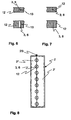
- FIG. 6 shows an embodiment of a seal 12 with air support.
- compressed air is introduced via the compressed air bore. Due to the overpressure in the thread inlet opening 3 and the thread outlet opening 6, the oil or the oil mist remains in the housing 2 and can not escape through the thread inlet opening 3 and the thread outlet opening 6.
- FIG. 7 shows an embodiment of a seal 12 without air support.
- the thread inlet opening 3 and the thread outlet 6 is made very tight.
- the thread 1 contacts respective opening 3 or 6 and takes the excess oil, which runs into the opening 3 and 6 with. Thus, the oil does not drip from the housing 2, but additionally wets the thread. 1
- FIG. 8 shows a multi-filament housing 2.
- a housing 2 a plurality of thread inlet openings 3 and the yarn outlet openings 6 are arranged. All threads 1 can be placed in the housing 2 at the same time.
- the distances of the yarn passages are dimensioned according to the machine-related distances from this representation is beyond the division not only of the housing 2, but also the seals 12 can be seen, which facilitates the insertion of the threads.
- FIG. 9 shows the housing 2 FIG. 4 in closed position in cross section.
- the divisible housing 2 is sealed with the seal 24.
- the seal 24 surrounds the entire housing 2.
- the baffle plate 17 is pressed against the main body of the swirler 5, whereby the yarn channel of the oil swirling device is closed.
- the baffle plate 17 is made with the spring 16 to ensure a secure closing of the yarn channel.
- the yarn channel is semicircular.
- FIGS. 10 and 11 Different variants of the yarn channel of the preparation device 4 and the swirling device 5 are in the FIGS. 10 and 11 shown.
- the yarn channel has a 3/4 circular cross-section
- the yarn channel is formed with a V-shaped channel cross-section.
- different channel cross sections may be particularly well suited for a preparation of the thread.
Landscapes
- Engineering & Computer Science (AREA)
- Textile Engineering (AREA)
- Mechanical Engineering (AREA)
- Physics & Mathematics (AREA)
- Fluid Mechanics (AREA)
- Yarns And Mechanical Finishing Of Yarns Or Ropes (AREA)
- Treatment Of Fiber Materials (AREA)
- Spinning Methods And Devices For Manufacturing Artificial Fibers (AREA)
- External Artificial Organs (AREA)
Description
- Die Erfindung betrifft eine Vorrichtung und ein Verfahren zum Präparationsauftrag auf Fäden mit einem Gehäuse, welches eine Einlassöffnung und eine Auslassöffnung für einen Faden und eine in dem Gehäuse angeordnete Präparationseinrichtung aufweist.
- Es gibt unterschiedliche bekannte Verfahren und Möglichkeiten zum Auftragen von Präparationen auf einen Faden bzw. ein Garn. Der Auftrag erfolgt z.B. indem das Garn über Walzen, die durch ein Ölbad rotieren, geführt und mit Öl benetzt wird. Eine weitere Möglichkeit besteht darin, dass das Garn über einen Präparationsstift läuft. Der Stift hat eine Bohrung über die Präparationsöl zugeführt wird und das Garn erhält den Ölauftrag über den Kontakt mit dem Stift. Dann gibt es Verfahren, bei denen die Präparation durch Ölsprühnebel oder eine Kombination von Verwirbelung mit Ölzufuhr aufgebracht wird.
- Aus der
DE 102 26 291 A1 sind ein Verfahren und eine Vorrichtung zum Präparieren eines synthetischen Filamentbündels bekannt. Dabei werden das Verwirbelungsmedium und das Präparationsmittel gemeinsam zugeführt. - In der
DE 102 20 508 A1 ist eine solche Vorrichtung beschrieben. Die Verwirbelungsölvorrichtung sitzt in einem Gehäuse, das zum Fadenanlegen geöffnet werden kann. Unter dem Gehäuse sitzt ein gekrümmtes Rohr, das zum Fadenanlegen einen Einfädelschlitz aufweist. Das Rohr dient zur Rückführung der überschüssigen Präparation. Die Verwirbelungsdüse hat einen Einfädelschlitz, in den der Faden eingelegt werden kann. Die Düse bleibt auch im Betriebszustand geöffnet. Positiv an dieser Vorrichtung ist, dass durch die Verwirbelung mit Ölauftrag eine gute Durchmischung der Garnfilamente mit dem Präparationsöl erfolgt. Nachteilig an dieser Ausführung ist, dass die Verwirbelungsdüse einen offenen Garnkanal aufweist und nicht gewährleistet werden kann, dass der Faden immer vom Luft/Ölstrahl gleichmäßig erfasst wird. Weiterhin nachteilig an dieser Ausführung ist, dass durch die Öffnungsschlitze des Gehäuses und Rohres überschüssiger Präparationsnebel oder auch Präparation geblasen wird. - Die
DE 102 05 005 A1 beschreibt eine Präparationsvorrichtung, bei der die Präparation durch einen Sprühnebel aufgetragen wird. Die auf das Garn abgestimmte Dosierung erfolgt mit Hilfe einer Blende, die einen Teil des Sprühstrahls vor dem Garn abschirmt. Die überschüssige Präparation wird über ein Fangblech in dem Sprühkasten aufgefangen und über einen Ablass in den Ölkreislauf zurückgeführt. Der Nachteil dieser Ausführung ist, dass mehr Öl als benötigt wird in Umlauf gebracht wird und nicht der ganze überschüssige Ölnebel über das Fangblech aufgefangen wird und somit ein Teil des Ölnebels durch die Ein- und Auslassöffnungen des Sprühkastens entweicht. Ein weiterer Nachteil ist, dass der Ölauftrag mit Hilfe des Sprühnebels nur oberflächlich erfolgt und das Öl nicht komplett mit den Garnfilamenten vermischt wird. - Besonders bei hohen Spinngeschwindigkeiten kann das Garn durch einen oberflächlichen Präparationsauftrag nicht genügend Präparation aufnehmen und es kommt im Prozess oder auch im nachfolgenden weiterverarbeitenden Prozess zu Störungen.
- Aufgabe der Erfindung ist es, eine Präparationsvorrichtung zu schaffen, bei der dem Garn genau dosiert die Garnpräparation zugeführt und mit dem Garn vermischt wird und die Vorrichtung so auszuführen, dass die überschüssige Präparation oder der Ölnebel nicht aus der Vorrichtung heraustreten kann, sondern zur Wiederverwendung abgeführt wird.
- Die Aufgabe wird gelöst mit einer Vorrichtung und einem Verfahren mit den Merkmalen der unabhängigen Ansprüche.
- Die Erfindung betrifft eine Vorrichtung zum Präparationsauftrag auf Fäden. Sie weist ein Gehäuse auf, welche eine Einlassöffnung und eine Auslassöffnung für den Faden hat. In dem Gehäuse ist eine Präparationseinrichtung angeordnet. Erfindungsgemäß ist das Gehäuse an der Einlass- und Auslassöffnung geteilt, so dass der Faden problemlos in das Gehäuse eingelegt werden kann. Durch die Teilung des Gehäuses wird vermieden, dass der Faden durch eine kleine Öffnung des Gehäuses eingefädelt, durch das Gehäuse geführt und am Ende des Gehäuses wieder aus dem Gehäuse herausgeführt werden muß. Dieser beträchtliche Arbeitsaufwand ist mit der vorliegenden Erfindung nicht mehr erforderlich, da das Gehäuse im Bereich der Einlass- und Auslassöffnung geteilt ist und hier geöffnet werden kann. Im geöffneten Zustand des Gehäuses wird der Faden quer zur Durchlaufrichtung in das Gehäuse eingelegt und das Gehäuse anschließend wieder geschlossen. Der Faden Ist somit bereit für eine Präparation, insbesondere mit Präparationsöl. Durch die Teilung des Gehäuses an der Einlass- und Auslassöffnung kann das Gehäuse durch eine Schwenkbewegung oder eine lineare Bewegung in Fadendurchlaufrichtung geöffnet werden.
- Neben dem leichteren Einfädeln des Fadens in das Gehäuse besteht gegenüber dem Stand der Technik der weitere Vorteil, dass das Gehäuse während des Präparierens des Fadens weitgehend geschlossen ist. Lediglich an den Ein- und Auslassöffnungen ist einerseits ausreichend Platz vorhanden um den Faden hindurchtreten zu lassen, andererseits sind sie aber so eng, dass sie abdichtend wirken. Präparationsmittel tritt aus diesen Öffnungen kaum aus. Anders als im Stand der Technik wird hierdurch Präparationsmittel gespart und darüber hinaus die Umgebung der Vorrichtung nicht verschmutzt.
- Um eine Verschmutzung der Umgebung der Vorrichtung zu vermeiden, ist es daher besonders vorteilhaft, wenn die Gehäuseteilung und/oder die Einlass- und Auslassöffnung abgedichtet sind oder wirken. Die Abdichtung sorgt dafür, dass das Präparationsmittel innerhalb des Gehäuses verbleibt Obwohl das Gehäuse für das einfache Einführen des Fadens in das Gehäuse geteilt ist, wird hierdurch eine Verschmutzung der Umgebung des Gehäuses vermieden.
- Ist dem Gehäuse eine Sammeleinrichtung für wiederverwendbare Präparationsflüssigkeit zugeordnet, so kann die Flüssigkeit auch innerhalb des Gehäuses gesammelt und der Präparationseinrichtung oder einem Sammelbehälter zugeführt werden.
- Besonders vorteilhaft ist es, wenn die Präparationseinrichtung eine Verwirbelungsvorrichtung und eine Ölvorrichtung ist. Hierdurch wird ein gleichmäßiger Auftrag des Präparationsmittels, insbesondere Öl, auf den Faden bewirkt. Durch die Verwirbelungsvorrichtung wird das Öl gleichmäßig zerstäubt und kann hierdurch den Faden gleichmäßig benetzen.
- Weist die Präparationsvorrichtung zum Einlegen des Fadens einen geteilten Garnkanal auf, so ist das Einlegen des Fadens in die Präparationsvorrichtung sehr einfach möglich, indem der Garnkanal in der Präparationsvorrichtung geöffnet wird. Nachdem sich der Faden in dem geteilten Garnkanal befindet, wird die Präparationsvorrichtung wieder geschlossen und ist bereit für die Präparation des Fadens.
- Für die Abdichtung der Einlass- und Auslassvorrichtung sind unter anderem eine Labyrinthdichtung, eine den Faden eng umschließende Öffnung, Unterdruck in dem Gehäuse und/oder eine druckluftbeaufschtagte Dichtung an der Einlass- und Auslassöffnung vorteilhaft. Die Labyrinthdichtung ist ebenso wie die den Faden eng umschließende Öffnung der Einlass- oder Auslassöffnung rein konstruktiv zu lösen. Häufig ist es allerdings ausreichend, wenn der Unterdruck in dem Gehäuse, welche beispielsweise durch die Absaugung der wiederverwendbaren Präparationsflüssigkeit entsteht, bereits eine ausreichende Abdichtung erzielt. Um eine besonders zuverlässige Abdichtung der Einlass- und Auslassöffnung zu erhalten, kann vorteilhafterweise vorgesehen werden, dass eine druckluftbeaufschlagte Dichtung an der jeweiligen Öffnung angeordnet ist. Wird an der Einlass- und Auslassöffnung jeweils Druckluft eingeblasen, so entsteht hier eine Art Luftvorhang, welcher das Hindurchtreten des Präparationsmittels weitgehend verhindert.
- Besonders einfach und kostengünstig ist es, wenn als eine Ölvorrichtung ein Stiftöler verwendet wird. Der an sich bekannte Stiftöler ist innerhalb des Gehäuses angeordnet und bewirkt, dass der an dem Stiftöler vorbeistreichende Faden gleichmäßig und ausreichend präpariert wird.
- Ist in dem Gehäuse ein Ölrücklauf angeordnet, so kann in besonders vorteilhafter Weise die wiederverwendbare Präparationsflüssigkeit gesammelt und einem dem Gehäuse zugeordneten Ölbehälter oder auch einem Gebrauchtölbehälter zugeführt werden.
- Um die Ölzufuhr, den Ölrücklauf und/oder die Druckluftzufuhr der Verwirbelungsvorrichtung je nach Bedarf einstellen zu können, um optimale Präparationsergebnisse des Fadens zu erhalten, ist es besonders vorteilhaft, wenn dem Gehäuse ein Regler zugeordnet ist. Über den Regel kann insbesondere die den Faden bzw. der Präparationseinrichtung zugeführte Ölmenge eingestellt werden. Über die Regelung der Druckluftzufuhr der Verwirbelungsvorrichtung kann darüber hinaus der Präparationsauftrag auf den speziellen Faden bzw. die gewünschte Menge des Präparationsauftrages eingestellt werden.
- Um eine exakte Führung des Fadens und einen optimalen Kontakt des Fadens mit dem Präparationsmittel zu erreichen, ist es vorteilhaft, wenn der Garnkanal mit einer federbeaufschlagten Prallplatte radial verschlossen ist. Über die Feder wird sichergestellt, dass die Prallplatte stets gegen eine Lagerfläche gedrückt wird und lediglich der Garnkanal für den Durchtritt des Fadens geöffnet bleibt. Insbesondere ein seitliches Ausweichen des Fadens aus dem Garnkanal heraus wird hierdurch vermieden. Der Faden wird ganz gezielt dem in dem Garnkanal auf den Faden einwirkenden Präparationsmit tel ausgesetzt Eine gleichbleibende Präparation ohne Verwendung einer unnötigen Menge von Präparationsmittel ist hierdurch gewährleistet.
- Besonders vorteilhaft ist es, wenn Teile des Gehäuses und der Präparationseinrichtung, welche mit dem Faden in Berührung kommen, aus verschleißfestem Material, insbesondere Keramik, hergestellt sind. Die Präparationseinrichtung und beispielsweise die Einlass- und Auslassöffnung des Gehäuses sind hierdurch verschleißgeschützt und gewährleisten einen langen Einsatz des Gehäuses.
- Die erfindungsgemäße Vorrichtung ist nicht nur für die Behandlung eines einzelnen Fadens, sondern auch für die Behandlung einer Fadenschar einsetzbar. Hierfür ist das Gehäuse mit mehreren Präparationseinrichtungen ausgestattet Insbesondere sind so viele Präparationseinrichtungen wie Fäden pro Spinnstelle vorhanden. Das gleichzeitige Einlegen einer Vielzahl von Fäden in ein einziges geöffnetes Gehäuse wird hierdurch besonders erleichtert Außerdem ist die Herstellung eines einzigen Gehäuses für eine Vielzahl von Fäden kostengünstiger als wenn einzelne Fäden separat präpariert werden würden.
- Öffnet sich die Präparationseinrichtung zusammen mit dem Öffnen des Gehäuses, so ist eine sehr einfache Handhabung gewährleistet. Der Faden wird dabei sowohl in die Einlass- und Auslassöffnung als auch in die Präparationseinrichtung selbst eingelegt. Anschließend wird das Gehäuse zusammen mit der Präparationseinrichtung wiederum geschlossen und der Faden steht für eine Präparation mit Präparationsmittel zur Verfügung.
- Bei einem erfindungsgemäßen Verfahren zum Präparationsauftrag auf Fäden in einem Gehäuse, welches eine Einlass- und eine Auslassöffnung für den Faden und eine Präparationseinrichtung zum Präparieren des Fadens mit Präparationsmittel aufweist, wird das Gehäuse zum Einlegen eines Fadens in Fadendurchlaufrichtung geöffnet und die Gehäuseteilung und/oder die Einlass- und Auslassöffnung beim Schließen des Gehäuses abgedichtet. Hierdurch wird der Faden sehr schnell zur Präparation vorbereitet Durch das dichte Schließen des Gehäuses nach dem Einlegen des Fadens wird das Gehäuse weitgehend abgeschlossen, so dass kein Präparationsmittel aus dem Gehäuse austritt. Eine Präparation des Fadens wird hierdurch sowohl sehr zuverlässig als auch ohne Verlust von Präparationsmittel sehr kostengünstig ermöglicht
- Wird das Gehäuse an der Einlass- und Auslassöffnung geteilt, so ist das Einlegen des Fadens besonders einfach möglich. Ein Einfädeln in Ösen wird hierdurch vermieden.
- Wird beim Öffnen des Gehäuses die Luft- und/oder Präparationsflüssigkeitszufuhr in das Gehäuse unterbrochen, so wird sichergestellt, dass Präparationsflüssigkeit nicht aus dem Gehäuse gelangt Eine Verschmutzung der Umgebung des Gehäuses wird vermieden.
- Ober eine Steuerung der Luft- und/oder Präparationsflüssigkeitszufuhr kann bewirkt werden, dass in vorteilhafter Weise beim Schließen des Gehäuses die Luft- und/oder Präparationsflüssigkeitszufuhr selbständig in Betrieb genommen wird. Das Wiederingangsetzen nach einem Fadenbruch kann hierdurch sehr einfach durchgeführt werden indem das Gehäuse geöffnet wird, wobei sich automatisch die Luft- und/oder Präparationsflüssigkeitszufuhr abstellt, anschließend der Faden in das Gehäuse und in die Präparationseinrichtung eingelegt wird und schließlich das Gehäuse wieder geschlossen und die Luft und/oder Präparationsflüssigkeitszufuhr wieder In Betrieb genommen wird.
- Besonders einfach und schnell ist die Neueinfädelung des Fadens möglich, wenn zusammen mit dem Öffnen des Gehäuses die Präparationseinrichtung ebenfalls geöffnet wird. Es ist lediglich ein Handgriff erforderlich, um das Gehäuse und die Präparationseinrichtung zu öffnen und wiederum zu schließen.
- Wird die Einlass- und Auslassöffnung mit Druckluft abgedichtet, so wird ein bzgl. des Präparationsmittels sehr dichtes Gehäuse erhalten, bei welchem die Einlass- und Auslassöffnungen relativ groß ausgeführt werden können, so dass der Faden ohne Behinderung durch das Gehäuse hindurchbewegt werden kann.
- Weitere Vorteile der Erfindung sind in den nachfolgenden Ausführungsbeispielen beschrieben. Es zeigt:
- Figur 1
- eine erfindungsgemäße Vorrichtung zum Präparationsauftrag,
- Figur 2
- eine weitere erfindungsgemäße Vorrichtung,
- Figur 3
- eine Präparationseinrichtung,
- Figur 4
- eine erfindungsgemäße Vorrichtung in geöffneter Stellung im Querschnitt,
- Figur 5
- eine weitere erfindungsgemäße Vorrichtung in geöffneter Stellung,
- Figur 6
- eine Dichtungsausführung mit Luftunterstützung in Quer- und Längsschnitt,
- Figur 7
- eine Dichtungsausführung ohne Luftunterstützung in Quer- und Längsschnitt,
- Figur 8
- eine erfindungsgemäße Vorrichtung für mehrere Fäden,
- Figur 9
- eine Vorrichtung gemäß
Figur 4 in geschlossener Stellung, - Figur 10
- einen Querschnitt aus einer Präparationseinrichtung und
- Figur 11
- einen Querschnitt einer weiteren Präparationseinrichtung.
-
Figur 1 zeigt eine komplette erfindungsgemäße Vorrichtung zum Präparationsauftrag. Ein Faden 1 läuft durch eine Fadeneinlassöffnung 3 eines Gehäuses 2, wird in der Präparationseinrichtung 4, hier einem Süftöler, mit Öl als Präparationsmittel benetzt und anschließend in einer Verwirbelungsvorrichtung 5 verwirbelt. Durch die Verwirbelung erfolgt ein gleichmäßiges Vermischen und Benetzen der einzelnen Filamente des Fadens 1 mit dem Öl. Nach der Verwirbelung tritt der Faden 1 am anderen Ende durch eine Auslassöffnung 6 aus dem Gehäuse 2. - Die Ölzufuhr aus einem Ölbehälter 7 wird mit einem Ölregler 8 gesteuert Der Faden 1 tangiert die Präparationseinrichtung 4 und wird mit Öl, das aus einer Zufuhrbohrung der Präparationseinrichtung 4 fließt, beaufschlagt. Die Ausführung der Präparationseinrichtung 4 kann nach dem derzeitigen Stand der Technik, wie allgemein bekannt, sein. In Fadendurchlaufrichtung nach der Präparationseinrichtung 4 befindet sich die Verwirbelungsvorrichtung 5. Der Faden 1 durchläuft einen geschlossenen Garnkanal 9 der Verwirbelungsvorrichtung 5 und wird über einen Druckluftkanal 10 mit Druckluft beaufschlagt. Die Druckluftzufuhr wird über einen Druckregler 11 reguliert. Die Luftmenge wird über den Verwirbelungsdruck und die Form des Druckluftkanals 10 bestimmt.
- Die Fadeneinlassöffnung 3 und die Fadenauslassöffnung 6 sind als Dichtung 12 ausgeführt. Die Abdichtung erfolgt mittels eines Luftstroms, der seitlich durch Druckluftbohrungen 13 der Dichtung 12 zugeführt wird. Durch den Druckaufbau in der Fadeneinlassöffnung 3 und der Fadenauslassöffnung 6 kann kein Öl oder Ölnebel austreten.
- Das Gehäuse 2 ist im unteren Bereich mit einer Vertiefung 20 versehen, in welcher sich das nicht von dem Faden 1 aufgenommene Öl sammelt und über einen Ölrücklauf 14 und einen Ölrücklaufregler 15 zurück in den Ölbehälter 7 geleitet und seiner erneuten Verwendung zugeführt wird.
- Um den Garnkanal 9 radial geschlossen zu halten und damit den Faden 1 mit dem Öl ordnungsgemäß und gleichmäßig verwirbeln zu können, ist ein Teil des Garnkanals 9 als eine mit einer Feder 16 vorgespannte Prallplatte 17 ausgeführt. Die Prallplatte 17 drückt dabei gegen den Grundkörper der Verwirbelungsvorrichtung 5 und dichtet den Garnkanal 9 radial ab.
-
Figur 2 zeigt eine weitere Ausführung der Vorrichtung. Die Präparationseinrichtung 4 und die Verwirbelungsvorrichtung 5 sind in einer Einheit zusammengefasst Der Faden 1 durchläuft den gemeinsamen Garnkanal 9 der Präparationseinrichtung 4 und der Verwirbelungsvorrichtung 5 und wird hier zunächst mit Öl benetzt und anschließend mit Druckluft beaufschlagt - Die Dichtungen 12 an der Fadeneinlassöffnung 3 und der Fadenauslassöffnung 6 sind ohne zusätzliche Luftbohrungen. Die Abdichtung nach außen erfolgt durch enge Garndurchlässe und/oder Unterdruck in dem Gehäuse 2, der über die Ölrücklaufleitung 14 erzeugt wird. Das überschüssige Öl wird über die Ölrücklaufleitung 14 in den Ölbehälter 7 zurück geführt. Neben dem rückgeführten Öl wird dem Ölbehälter 7 frisches Öl über eine Ölversorgung 18 zugeführt.
-
Figur 3 zeigt eine kombinierte Öl-Verwirbelungsvorrichtung. Die Ölzufuhrleitung 22 und der Druckluftkanal 10 treffen sich in einem gemeinsamen Kanal. Das sich dadurch ergebende Öl-Luftgemisch trifft gemeinsam in den Garnkanal 9 und beaufschlagt den Faden 1. Damit erfolgt ein intensiverer Ölauftrag und die Ölmenge kann reduziert werden. Der Garnkanal 9 wird wiederum mit der Prallplatte 17 verschlossen. -
Figur 4 zeigt das Gehäuse 2 in geöffneter Stellung im Querschnitt. Eine Hälfte 2' des Gehäuses 2 mit Prallplatte 17 und Feder 16 ist über ein Gelenk 23 radial von der Hälfte 2" aufgeschwenkt. Somit werden die Garnkanäle der Dichtungen 12 (nicht dargestellt) an der Fadeneinlassöffnung 3 und der Fadenauslassöffnung 6 sowie der Präparationseinrichtung 4 und der Verwirbelungsvorrichtung 5 geöffnet und der Faden 1 kann eingelegt werden. Nach dem Schließen der Hälfte 2' wird der Garnkanal 9 mit der federbeaufschlagten Prallplatte 17 verschlossen. Das Gehäuse 2 wird an Trennstellen der beiden Hälften 2' und 2" mit einer Dichtung 24 abgedichtet. Die Betätigung des Öffnen/Schließmechanismus kann manuell erfolgen oder mit der Maschinensteuerung automatisch gekoppelt sein. Besonders vorteilhaft ist es, wenn zusammen mit dem Öffnen des Gehäuses 2 die Druckluftzufuhr und die Ölzufuhr gestoppt wird. Nach dem Schließen des Gehäuses 2 kann sie entweder manuell oder automatisch wieder in Betrieb genommen werden. -
Figur 5 zeigt ein Gehäuse 2, welches ähnlich derFigur 4 aufgebaut ist Die Hälften 2' und 2" sind zum Öffnen und Schließen allerdings linearbeweglich ausgeführt. Hierfür ist eine Schiebevorrichtung 25 vorgesehen. Die Hälfte 2' mit Prallplatte 17 und Feder 16 wird geradlinig geöffnet, um den Faden 1 einzulegen. Die Betätigung kann wiederum manuell oder mit der Maschinensteuerung automatisch erfolgen. -
Figur 6 zeigt eine Ausführung einer Dichtung 12 mit Luftunterstützung. In den Garnkanal der Fadeneinlassöffnung 3 und der Fadenauslassöffnung 6 wird über die Druckluftbohrung 13 Druckluft eingebracht. Durch den Überdruck in der Fadeneinlassöffnung 3 und der Fadenauslassöffnung 6 bleibt das Öl oder der Ölnebel in dem Gehäuse 2 und kann nicht durch die Fadeneinlassöffnung 3 und die Fadenauslassöffnung 6 entweichen. -
Figur 7 zeigt eine Ausführung einer Dichtung 12 ohne Luftunterstützung. Die Fadeneinlassöffnung 3 und die Fadenauslassöffnung 6 ist sehr eng ausgeführt. Der Faden 1 kontaktiert jeweilige Öffnung 3 bzw. 6 und nimmt das überschüssige Öl, das in die Öffnung 3 bzw. 6 hineinläuft mit. Somit tropft das Öl nicht aus dem Gehäuse 2, sondern benetzt zusätzlich den Faden 1. -
Figur 8 zeigt ein mehrfädiges Gehäuse 2. In einem Gehäuse 2 sind mehrere Fadeneinlassöffnungen 3 bzw. die Fadenauslassöffnungen 6 angeordnet. Es können alle Fäden 1 gleichzeitig in das Gehäuse 2 eingelegt werden. Die Abstände der Garndurchlässe werden nach den maschinenbedingten Abständen dimensioniert Aus dieser Darstellung ist darüber hinaus die Teilung nicht nur des Gehäuses 2, sondern auch der Dichtungen 12 ersichtlich, welche das Einlegen der Fäden erleichtert. -
Figur 9 zeigt das Gehäuse 2 ausFigur 4 in geschlossener Stellung im Querschnitt. Das teilbare Gehäuse 2 ist mit der Dichtung 24 abgedichtet Die Dichtung 24 umgibt das gesamte Gehäuse 2. - Die Prallplatte 17 wird gegen den Grundkörper der Verwirbelungsvorrichtung 5 gedrückt, wodurch der Garnkanal der Öl-Verwirbelungsvorrichtung geschlossen wird. Die Prallplatte 17 wird mit der Feder 16 angestellt um eine gesichertes Schließen des Garnkanals zu gewährleisten. Der Garnkanal ist halbkreisförmig ausgeführt.
- Verschiedene Varianten des Garnkanals der Präparationseinrichtung 4 und der Verwirbelungsvorrichtung 5 sind in den
Figuren 10 und 11 gezeigt. InFigur 10 weist der Garnkanal einen 3/4-Kreisquerschnitt auf, während in Figur 11 der Garnkanal mit einem V-förmigen Kanalquerschnitt ausgebildet ist. Je nach Art des Fadens 1 können sich unterschiedliche Kanalquerschnitte besonders gut für eine Präparation des Fadens eignen.
Claims (19)
- Vorrichtung zum Präparationsauftrag auf Fäden mit einem Gehäuse (2), welches eine Einlassöffnung (3) und eine Auslassöffnung (6) für einen Faden (1) und eine in dem Gehäuse (2) angeordnete Präparationseinrichtung (4) aufweist, dadurch gekennzeichnet, dass das Gehäuse (2) an der Einlass- und Auslassöffnung (3, 6) geteilt ist zum Einlegen des Fadens (1) in das Gehäuse (2), und dass die Gehäuseteilung und/oder die Einlass- und Auslassöffnung (3, 6) abgedichtet sind, wobei sich in Fadendurchlaufrichtung nach der Präparationseinrichtung (4) eine Verwirbelungsvorrichtung (5) befindet.
- Vorrichtung nach dem vorherigen Anspruch, dadurch gekennzeichnet, dass dem Gehäuse (2) eine Sammeleinrichtung für wiederverwendbare Präparationsflüssigkeit zugeordnet ist.
- Vorrichtung nach einem der vorherigen Ansprüche, dadurch gekennzeichnet, dass die Präparationseinrichtung (4) eine Ölvorrichtung ist.
- Vorrichtung nach einem der vorherigen Ansprüche, dadurch gekennzeichnet, dass die Präparationseinrichtung (4) zum Einlegen des Fadens (1) einen geteilten Garnkanal (9) aufweist.
- Vorrichtung nach einem der vorherigen Ansprüche, dadurch gekennzeichnet, dass die Abdichtung der Einlass- und Auslassöffnung (3, 6) eine Labyrinthdichtung, eine den Faden (1) eng umschließende Öffnung, Unterdruck in dem Gehäuse (2) und/oder eine druckluftbeaufschlagte Dichtung ist.
- Vorrichtung nach einem der vorherigen Ansprüche, dadurch gekennzeichnet, dass die Präparationseinrichtung (4) ein Stiftöler ist.
- Vorrichtung nach einem der vorherigen Ansprüche, dadurch gekennzeichnet, dass an dem Gehäuse (2) ein Ölrücklauf (14) angeordnet ist.
- Vorrichtung nach einem der vorherigen Ansprüche, dadurch gekennzeichnet, dass dem Gehäuse (2) ein Ölbehälter (7) zugeordnet ist.
- Vorrichtung nach einem der vorherigen Ansprüche, dadurch gekennzeichnet, dass dem Gehäuse (2) Regler (8, 11,15) für die Ölzufuhr, den Ölrücklauf und/oder die Druckluftzufuhr der Verwirbelungsvorrichtung (5) zugeordnet sind.
- Vorrichtung nach einem der vorherigen Ansprüche, dadurch gekennzeichnet, dass der Garnkanal (9) mit einer federbeaufschlagten Prallplatte (16, 17) radial verschlossen ist.
- Vorrichtung nach einem der vorherigen Ansprüche, dadurch gekennzeichnet, dass Teile des Gehäuses (2) und der Präparationseinrichtung (4), welche mit dem Faden (1) in Berührung kommen, aus verschleißfestem Material, insbesondere Keramik hergestellt sind.
- Vorrichtung nach einem der vorherigen Ansprüche, dadurch gekennzeichnet, dass in einem Gehäuse (2) mehrere Präparationseinrichtungen (4), insbesondere so viele Präparationseinrichtungen (4) wie Fäden (1) pro Spinnstelle vorhanden sind, angeordnet sind.
- Vorrichtung nach einem der vorherigen Ansprüche, dadurch gekennzeichnet, dass sich zusammen mit dem Öffnen des Gehäuses (2) die Präparationseinrichtung (4) öffnet.
- Verfahren zum Präparationsauftrag von Fäden in einem Gehäuse (2), welches eine Einlassöffnung (3) und eine Auslassöffnung (6) für den Faden (1) und eine in dem Gehäuse (2) angeordnete Präparationseinrichtung (4) sowie eine Verwirbelungseinrichtung (5) aufweist, dadurch gekennzeichnet, dass das Gehäuse (2) zum Einlegen eines Fadens (1) in Fadendurchlaufrichtung geöffnet, und dass die Gehäuseteilung und/oder die Einlass- und Auslassöffnung (3, 6) beim Schließen des Gehäuses (2) abgedichtet wird, wobei in Fadendurchlaufrichtung nach einer Präparation mit einer Präparationsflüssigkeit eine Verwirbelung erfolgt.
- Verfahren nach dem vorherigen Anspruch, dadurch gekennzeichnet, dass das Gehäuse (2) an der Einlass- und Auslassöffnung (3, 6) geteilt wird.
- Verfahren nach einem der vorherigen Ansprüche, dadurch gekennzeichnet, dass beim Öffnen des Gehäuses (2) die Luft- und/oder Präparationsflüssigkeitszufuhr unterbrochen wird.
- Verfahren nach einem der vorherigen Ansprüche, dadurch gekennzeichnet, dass beim Schließen des Gehäuses (2) die Luft- und/oder Präparationsflüssigkeitszufuhr in Betrieb genommen wird.
- Verfahren nach einem der vorherigen Ansprüche, dadurch gekennzeichnet, dass zusammen mit dem Öffnen des Gehäuses (2) die Präparationseinrichtung (4) geöffnet wird.
- Verfahren nach einem der vorherigen Ansprüche, dadurch gekennzeichnet, dass die Einlass- und Auslassöffnung (3, 6) mit Druckluft abgedichtet wird.
Applications Claiming Priority (2)
| Application Number | Priority Date | Filing Date | Title |
|---|---|---|---|
| DE102004017210A DE102004017210A1 (de) | 2004-04-10 | 2004-04-10 | Vorrichtung und ein Verfahren zum Präparationsauftrag auf Fäden |
| PCT/EP2005/051573 WO2005098104A1 (de) | 2004-04-10 | 2005-04-08 | Vorrichtung und ein verfahren zum präparationsauftrag auf fäden |
Publications (2)
| Publication Number | Publication Date |
|---|---|
| EP1735487A1 EP1735487A1 (de) | 2006-12-27 |
| EP1735487B1 true EP1735487B1 (de) | 2011-03-30 |
Family
ID=34964134
Family Applications (1)
| Application Number | Title | Priority Date | Filing Date |
|---|---|---|---|
| EP05731712A Expired - Lifetime EP1735487B1 (de) | 2004-04-10 | 2005-04-08 | Vorrichtung und ein verfahren zum präparationsauftrag auf fäden |
Country Status (7)
| Country | Link |
|---|---|
| US (1) | US20070158485A1 (de) |
| EP (1) | EP1735487B1 (de) |
| JP (1) | JP4904257B2 (de) |
| CN (1) | CN1969069B (de) |
| AT (1) | ATE503871T1 (de) |
| DE (2) | DE102004017210A1 (de) |
| WO (1) | WO2005098104A1 (de) |
Families Citing this family (17)
| Publication number | Priority date | Publication date | Assignee | Title |
|---|---|---|---|---|
| CN101765683B (zh) * | 2007-07-25 | 2011-05-25 | 欧瑞康·赫伯利·泰姆考有限公司 | 用于处理多纤维长丝的装置 |
| DE102008018395A1 (de) | 2008-04-10 | 2009-10-15 | Rpe Technologies Gmbh | Präparationsvorrichtung |
| JP5509559B2 (ja) * | 2008-09-10 | 2014-06-04 | 東レ株式会社 | カーボンナノチューブ連続繊維の製造方法および製造装置 |
| DE102008052036A1 (de) | 2008-10-16 | 2010-04-22 | Oerlikon Textile Gmbh & Co. Kg | Präparationsvorrichtung zum Präparieren eines Fadens |
| CN101407943B (zh) * | 2008-11-11 | 2010-12-08 | 江苏恒力化纤有限公司 | 一种油剂防腐方法 |
| CN101649498B (zh) * | 2009-08-27 | 2011-04-27 | 江苏宏源纺机股份有限公司 | 上油装置 |
| JP5448901B2 (ja) * | 2010-02-15 | 2014-03-19 | Tmtマシナリー株式会社 | 油剤拡散装置及び紡糸巻取機 |
| CN102249122B (zh) * | 2011-07-20 | 2012-12-12 | 海宁市建利纺织有限公司 | 化纤丝的退绕上油装置 |
| WO2015144440A1 (de) * | 2014-03-27 | 2015-10-01 | Oerlikon Textile Gmbh & Co. Kg | Vorrichtung zum abziehen und behandeln einer fadenschar |
| CN105803544B (zh) * | 2016-05-27 | 2017-12-19 | 浙江显昱纤维织染制衣有限公司 | 一种纺丝机的上油结构 |
| CN106521644A (zh) * | 2016-12-05 | 2017-03-22 | 江苏吉星光通讯科技有限公司 | 空变纱前纺工艺中的喷丝板 |
| CN107904813B (zh) * | 2017-10-19 | 2021-06-15 | 安徽工程大学 | 一种用于纺织机的自动润滑装置 |
| CN108796886A (zh) * | 2018-08-30 | 2018-11-13 | 张家港市利佳纺织有限公司 | 一种包覆氨纶添加剂处理系统 |
| CN111394853B (zh) * | 2020-04-30 | 2021-07-23 | 浙江佳人新材料有限公司 | 一种再生多丽竹节丝生产工艺 |
| CN111534872B (zh) * | 2020-04-30 | 2021-08-10 | 浙江佳宝聚酯有限公司 | 一种新型复合仿毛纤维的制备方法 |
| CN111977989A (zh) * | 2020-09-08 | 2020-11-24 | 重庆国际复合材料股份有限公司 | 一种用于玻璃纤维的涂油装置 |
| CN112981569B (zh) * | 2021-02-03 | 2022-04-12 | 新疆金大禹环境科技有限公司 | 一种化纤生产加工用导流全包式上油辊 |
Family Cites Families (48)
| Publication number | Priority date | Publication date | Assignee | Title |
|---|---|---|---|---|
| US2120110A (en) * | 1937-03-04 | 1938-06-07 | Benjamin Brenner | Yarn oiler for coning machines |
| US2182573A (en) * | 1939-05-04 | 1939-12-05 | Amon Joseph | Yarn moistening apparatus |
| US2536208A (en) * | 1942-12-22 | 1951-01-02 | Western Electric Co | Method of treating strands |
| US2428284A (en) * | 1943-08-18 | 1947-09-30 | Western Electric Co | Strand marking apparatus |
| US2708843A (en) * | 1950-08-10 | 1955-05-24 | Chemstrand Corp | Fluid treating apparatus for strands |
| US2674112A (en) * | 1951-12-13 | 1954-04-06 | Celanese Corp | Textile apparatus |
| US2871090A (en) * | 1953-06-29 | 1959-01-27 | Ind Rayon Corp | Method for the manufacture and treatment of polyamide fibers |
| US2947595A (en) * | 1955-01-24 | 1960-08-02 | Celanese Corp | Treatment of filamentary materials |
| US3004865A (en) * | 1959-10-16 | 1961-10-17 | Henry J Schmitz | Apparatus and method for moistening yarn or other thread |
| US3067600A (en) * | 1960-02-10 | 1962-12-11 | Morpul Inc | Apparatus for knitting undistorted looser stitches in selected portions of knitted articles |
| US3103731A (en) * | 1961-09-18 | 1963-09-17 | Eastman Kodak Co | Textile apparatus for bulking yarns and process |
| US3189506A (en) * | 1962-04-12 | 1965-06-15 | Eastman Kodak Co | Method and apparatus for forming continuous filament filter rods |
| US3166441A (en) * | 1962-05-08 | 1965-01-19 | Triangle Conduit & Cable Co In | Machine for color coating strands |
| US3162544A (en) * | 1962-10-08 | 1964-12-22 | Arthur J Cobert | Thread lubricating device |
| US3230745A (en) * | 1963-10-03 | 1966-01-25 | Monsanto Co | Continuous annealer |
| US3349580A (en) * | 1964-07-01 | 1967-10-31 | Valls Conrado | Device for the continuous treatment of textile materials |
| US3353344A (en) * | 1964-10-13 | 1967-11-21 | Du Pont | Fluid jet twister |
| US3403501A (en) * | 1966-07-15 | 1968-10-01 | Nuval Co | Yarn-treatment, method and apparatus |
| US3706192A (en) * | 1969-10-14 | 1972-12-19 | Akzona Inc | Process and apparatus for false twisting synthetic yarns |
| FR2094341A5 (de) * | 1970-06-18 | 1972-02-04 | Rhodiaceta | |
| US3739746A (en) * | 1971-06-03 | 1973-06-19 | Phillips Petroleum Co | Yarn coating device |
| US3725523A (en) * | 1971-08-03 | 1973-04-03 | Du Pont | Process for extracting and drawing a tow |
| JPS503831B2 (de) * | 1971-10-07 | 1975-02-10 | ||
| US3842680A (en) * | 1972-08-09 | 1974-10-22 | Bach Simpson Ltd | Gas blast wiping collar for cleaning pipettes |
| US3812665A (en) * | 1972-12-22 | 1974-05-28 | Eastman Kodak Co | Method and apparatus for forming random slubs in yarn |
| US3893411A (en) * | 1973-03-29 | 1975-07-08 | Josef Krausz | Yarn lubricator |
| DE2356220A1 (de) * | 1973-11-10 | 1975-05-15 | Bayer Ag | Vorrichtung zum falschzwirnen von synthetischen filament-garnen |
| DE2554132C2 (de) * | 1975-12-02 | 1982-06-16 | Karl 5600 Wuppertal Bous | Vorrichtung zum abschnittweise unterschiedlichen Färben von textilem Fadenmaterial, insbesondere von Garnen o.dgl. |
| JPS544816A (en) * | 1977-06-15 | 1979-01-13 | Nippon Oil Co Ltd | Mercury recovering method |
| CS199077B1 (en) * | 1977-08-17 | 1980-07-31 | Eduard Pallay | Method of and apparatus for manufacturing yarn from staple fibres in air vortex in a spinning tube |
| DE3033409A1 (de) * | 1980-09-05 | 1982-04-22 | Honeywell Gmbh, 6000 Frankfurt | Vorrichtung zur waermebehandlung von synthetischen faeden und garnen |
| US4414917A (en) * | 1983-01-03 | 1983-11-15 | Industrial Cleaning And Coating, Inc. | System for selectively treating cables and the like |
| DE3422031A1 (de) * | 1983-06-11 | 1985-04-18 | Barmag Barmer Maschinenfabrik Ag, 5630 Remscheid | Heizkammer fuer laufende faeden |
| IT1194553B (it) * | 1983-12-30 | 1988-09-22 | Snia Fibre | Procedimento monostadio per la produzione ad alta velocita' di fili continui sintetici a base poliammidica e relativi prodotti |
| US4811748A (en) * | 1986-04-04 | 1989-03-14 | Naniwa Seitei Kabushiki Kaisha | Method and apparatus for continuously applying surface treatment onto an article being fed along a pass line |
| GB2193232A (en) * | 1986-06-17 | 1988-02-03 | Rieter Ag Maschf | Thread treating nozzles |
| US5056185A (en) * | 1989-09-08 | 1991-10-15 | Hughes Aircraft Company | Optical fiber cleaner |
| CH681633A5 (de) * | 1990-07-02 | 1993-04-30 | Heberlein & Co Ag | |
| US6397444B1 (en) * | 1994-05-24 | 2002-06-04 | University Of Manchester Institute Of Science & Technology | Apparatus and method for texturing yarn |
| US5634236A (en) * | 1995-07-05 | 1997-06-03 | Lucent Technologies Inc. | Non-contact fiber cleaning and tensioning device |
| DE19945699A1 (de) * | 1998-10-02 | 2000-04-06 | Barmag Barmer Maschf | Vorrichtung zum Aufbringen eines flüssigen Präparationsmittels auf einen laufenden Faden |
| WO2000049212A1 (de) * | 1999-02-16 | 2000-08-24 | Temco Textilmaschinenkomponenten Gmbh | Verfahren zum einführen und anlegen von garn und falschdralltexturiereinrichtung |
| DE19909380A1 (de) * | 1999-02-16 | 2000-08-17 | Temco Textilmaschkomponent | Verfahren zum Einführen und Anlegen von Garn und Falschdralltexturiereinrichtung |
| US6868593B1 (en) * | 1999-09-22 | 2005-03-22 | Ryuji Mitsuhashi | Tandem interlacing textile jet nozzle assembly |
| GB0000786D0 (en) * | 2000-01-14 | 2000-03-08 | Univ Manchester | Apparatus for processing textile materials |
| US6495204B1 (en) * | 2000-09-27 | 2002-12-17 | Bechtel Bwxt Idaho, Llc | Methods for modifying monofilaments, bundles of monofilaments, and fibrous structural material |
| DE10220508B4 (de) * | 2001-05-15 | 2008-08-21 | Lurgi Zimmer Gmbh | Verfahren und Vorrichtung zur Behandlung eines Fadens |
| DE10226291A1 (de) * | 2002-06-13 | 2003-12-24 | Neumag Gmbh & Co Kg | Verfahren und Vorrichtung zum Präparieren eines synthetischen Filamentbündels |
-
2004
- 2004-04-10 DE DE102004017210A patent/DE102004017210A1/de not_active Withdrawn
-
2005
- 2005-04-08 JP JP2007506787A patent/JP4904257B2/ja not_active Expired - Fee Related
- 2005-04-08 AT AT05731712T patent/ATE503871T1/de active
- 2005-04-08 CN CN2005800187341A patent/CN1969069B/zh not_active Expired - Fee Related
- 2005-04-08 DE DE502005011189T patent/DE502005011189D1/de not_active Expired - Lifetime
- 2005-04-08 WO PCT/EP2005/051573 patent/WO2005098104A1/de not_active Ceased
- 2005-04-08 EP EP05731712A patent/EP1735487B1/de not_active Expired - Lifetime
-
2006
- 2006-10-10 US US11/548,116 patent/US20070158485A1/en not_active Abandoned
Also Published As
| Publication number | Publication date |
|---|---|
| US20070158485A1 (en) | 2007-07-12 |
| JP2007532787A (ja) | 2007-11-15 |
| CN1969069A (zh) | 2007-05-23 |
| CN1969069B (zh) | 2010-09-15 |
| DE102004017210A1 (de) | 2005-10-27 |
| ATE503871T1 (de) | 2011-04-15 |
| WO2005098104A1 (de) | 2005-10-20 |
| JP4904257B2 (ja) | 2012-03-28 |
| EP1735487A1 (de) | 2006-12-27 |
| DE502005011189D1 (de) | 2011-05-12 |
Similar Documents
| Publication | Publication Date | Title |
|---|---|---|
| DE102004017210A1 (de) | Vorrichtung und ein Verfahren zum Präparationsauftrag auf Fäden | |
| EP2329066B1 (de) | Luftdüsenspinnaggregat mit spindelförmigem bauteil | |
| DE1410816A1 (de) | Verfahren zur Behandlung von Fadenmaterial | |
| EP2454402A1 (de) | Bauteil für eine luftdüsenspinnvorrichtung | |
| EP2179084B1 (de) | Vorrichtung zur behandlung eines multifilen fadens | |
| EP3309281B1 (de) | Faserführungselement für eine spinndüse einer luftspinnmaschine sowie verfahren zum betrieb einer luftspinnmaschine | |
| DE2419617A1 (de) | Vorrichtung zum behandeln von garnoder bandfoermigem material | |
| EP0345670A2 (de) | Sprühkopf für Düsenfeuchter und Verfahren zum Befeuchten | |
| DE3130839C2 (de) | Drahtziehvorrichtung | |
| DE2502493A1 (de) | Garntexturierduese | |
| EP0615011B1 (de) | Spindel zur Herstellung eines Garns oder Zwirns | |
| DE2418854A1 (de) | Vorrichtung zum aufbringen einer fluessigkeit | |
| DE3616196A1 (de) | Verfahren und vorrichtung zum verflechten von faserbaendern | |
| DE4333716C1 (de) | Verfahren und Vorrichtungen zur Aufbringung von Präparationen auf Garne bzw. Fäden am laufenden Faden | |
| DE19945699A1 (de) | Vorrichtung zum Aufbringen eines flüssigen Präparationsmittels auf einen laufenden Faden | |
| DE3233744C2 (de) | Verfahren zum Mischen eines kunststoffhaltigen Spritzbetons und Düsenmischkörper zur Durchführung des Verfahrens | |
| DE1785439C3 (de) | Verfahren und Vorrichtung zum Eintragen eines örtlich schwerer gemachten Schußfadens | |
| EP1660708A1 (de) | Kanalplatte für eine offenend-rotorspinnvorrichtung | |
| DE2627268A1 (de) | Doppeldraht-zwirnspindel zum nasszwirnen | |
| EP0001988A1 (de) | Verfahren und Vorrichtung zum Einführen von laufenden Fäden in eine enge Öffnung mittels eines Gasstrahls | |
| DE3915691C2 (de) | Verfahren zur Stauchkammertexturierung und Vorrichtung zur Druchführung des Verfahrens | |
| DE1510687B1 (de) | Vorrichtung zum Markieren von Spinnkopsen | |
| EP0180715B1 (de) | Verfahren und Vorrichtung zum Kräuseln von Kabeln aus synthetischen Fäden | |
| DE3726507A1 (de) | Fadenspleissvorrichtung | |
| DE19617752A1 (de) | Verfahren und Vorrichtung zum Zuführen eines Schmier- oder Kühlmediums zu einer Verbrauchsstelle |
Legal Events
| Date | Code | Title | Description |
|---|---|---|---|
| PUAI | Public reference made under article 153(3) epc to a published international application that has entered the european phase |
Free format text: ORIGINAL CODE: 0009012 |
|
| 17P | Request for examination filed |
Effective date: 20060922 |
|
| AK | Designated contracting states |
Kind code of ref document: A1 Designated state(s): AT BE BG CH CY CZ DE DK EE ES FI FR GB GR HU IE IS IT LI LT LU MC NL PL PT RO SE SI SK TR |
|
| DAX | Request for extension of the european patent (deleted) | ||
| 17Q | First examination report despatched |
Effective date: 20080618 |
|
| GRAP | Despatch of communication of intention to grant a patent |
Free format text: ORIGINAL CODE: EPIDOSNIGR1 |
|
| GRAS | Grant fee paid |
Free format text: ORIGINAL CODE: EPIDOSNIGR3 |
|
| GRAA | (expected) grant |
Free format text: ORIGINAL CODE: 0009210 |
|
| AK | Designated contracting states |
Kind code of ref document: B1 Designated state(s): AT BE BG CH CY CZ DE DK EE ES FI FR GB GR HU IE IS IT LI LT LU MC NL PL PT RO SE SI SK TR |
|
| REG | Reference to a national code |
Ref country code: GB Ref legal event code: FG4D Free format text: NOT ENGLISH |
|
| REG | Reference to a national code |
Ref country code: CH Ref legal event code: EP |
|
| REG | Reference to a national code |
Ref country code: IE Ref legal event code: FG4D |
|
| REF | Corresponds to: |
Ref document number: 502005011189 Country of ref document: DE Date of ref document: 20110512 Kind code of ref document: P |
|
| REG | Reference to a national code |
Ref country code: DE Ref legal event code: R096 Ref document number: 502005011189 Country of ref document: DE Effective date: 20110512 |
|
| REG | Reference to a national code |
Ref country code: NL Ref legal event code: VDEP Effective date: 20110330 |
|
| PG25 | Lapsed in a contracting state [announced via postgrant information from national office to epo] |
Ref country code: LT Free format text: LAPSE BECAUSE OF FAILURE TO SUBMIT A TRANSLATION OF THE DESCRIPTION OR TO PAY THE FEE WITHIN THE PRESCRIBED TIME-LIMIT Effective date: 20110330 Ref country code: GR Free format text: LAPSE BECAUSE OF FAILURE TO SUBMIT A TRANSLATION OF THE DESCRIPTION OR TO PAY THE FEE WITHIN THE PRESCRIBED TIME-LIMIT Effective date: 20110701 Ref country code: SE Free format text: LAPSE BECAUSE OF FAILURE TO SUBMIT A TRANSLATION OF THE DESCRIPTION OR TO PAY THE FEE WITHIN THE PRESCRIBED TIME-LIMIT Effective date: 20110330 |
|
| PGFP | Annual fee paid to national office [announced via postgrant information from national office to epo] |
Ref country code: CH Payment date: 20110502 Year of fee payment: 7 |
|
| LTIE | Lt: invalidation of european patent or patent extension |
Effective date: 20110330 |
|
| PG25 | Lapsed in a contracting state [announced via postgrant information from national office to epo] |
Ref country code: SI Free format text: LAPSE BECAUSE OF FAILURE TO SUBMIT A TRANSLATION OF THE DESCRIPTION OR TO PAY THE FEE WITHIN THE PRESCRIBED TIME-LIMIT Effective date: 20110330 Ref country code: CY Free format text: LAPSE BECAUSE OF FAILURE TO SUBMIT A TRANSLATION OF THE DESCRIPTION OR TO PAY THE FEE WITHIN THE PRESCRIBED TIME-LIMIT Effective date: 20110330 Ref country code: FI Free format text: LAPSE BECAUSE OF FAILURE TO SUBMIT A TRANSLATION OF THE DESCRIPTION OR TO PAY THE FEE WITHIN THE PRESCRIBED TIME-LIMIT Effective date: 20110330 |
|
| PGFP | Annual fee paid to national office [announced via postgrant information from national office to epo] |
Ref country code: AT Payment date: 20110419 Year of fee payment: 7 |
|
| PGFP | Annual fee paid to national office [announced via postgrant information from national office to epo] |
Ref country code: DE Payment date: 20110502 Year of fee payment: 7 |
|
| REG | Reference to a national code |
Ref country code: IE Ref legal event code: FD4D |
|
| BERE | Be: lapsed |
Owner name: TEMCO COMPONENTS G.M.B.H. Effective date: 20110430 |
|
| PG25 | Lapsed in a contracting state [announced via postgrant information from national office to epo] |
Ref country code: PT Free format text: LAPSE BECAUSE OF FAILURE TO SUBMIT A TRANSLATION OF THE DESCRIPTION OR TO PAY THE FEE WITHIN THE PRESCRIBED TIME-LIMIT Effective date: 20110801 Ref country code: EE Free format text: LAPSE BECAUSE OF FAILURE TO SUBMIT A TRANSLATION OF THE DESCRIPTION OR TO PAY THE FEE WITHIN THE PRESCRIBED TIME-LIMIT Effective date: 20110330 |
|
| PG25 | Lapsed in a contracting state [announced via postgrant information from national office to epo] |
Ref country code: MC Free format text: LAPSE BECAUSE OF NON-PAYMENT OF DUE FEES Effective date: 20110430 Ref country code: CZ Free format text: LAPSE BECAUSE OF FAILURE TO SUBMIT A TRANSLATION OF THE DESCRIPTION OR TO PAY THE FEE WITHIN THE PRESCRIBED TIME-LIMIT Effective date: 20110330 Ref country code: RO Free format text: LAPSE BECAUSE OF FAILURE TO SUBMIT A TRANSLATION OF THE DESCRIPTION OR TO PAY THE FEE WITHIN THE PRESCRIBED TIME-LIMIT Effective date: 20110330 Ref country code: IS Free format text: LAPSE BECAUSE OF FAILURE TO SUBMIT A TRANSLATION OF THE DESCRIPTION OR TO PAY THE FEE WITHIN THE PRESCRIBED TIME-LIMIT Effective date: 20110730 Ref country code: ES Free format text: LAPSE BECAUSE OF FAILURE TO SUBMIT A TRANSLATION OF THE DESCRIPTION OR TO PAY THE FEE WITHIN THE PRESCRIBED TIME-LIMIT Effective date: 20110711 Ref country code: SK Free format text: LAPSE BECAUSE OF FAILURE TO SUBMIT A TRANSLATION OF THE DESCRIPTION OR TO PAY THE FEE WITHIN THE PRESCRIBED TIME-LIMIT Effective date: 20110330 |
|
| PG25 | Lapsed in a contracting state [announced via postgrant information from national office to epo] |
Ref country code: NL Free format text: LAPSE BECAUSE OF FAILURE TO SUBMIT A TRANSLATION OF THE DESCRIPTION OR TO PAY THE FEE WITHIN THE PRESCRIBED TIME-LIMIT Effective date: 20110330 |
|
| PG25 | Lapsed in a contracting state [announced via postgrant information from national office to epo] |
Ref country code: BE Free format text: LAPSE BECAUSE OF NON-PAYMENT OF DUE FEES Effective date: 20110430 Ref country code: IE Free format text: LAPSE BECAUSE OF FAILURE TO SUBMIT A TRANSLATION OF THE DESCRIPTION OR TO PAY THE FEE WITHIN THE PRESCRIBED TIME-LIMIT Effective date: 20110330 |
|
| PLBE | No opposition filed within time limit |
Free format text: ORIGINAL CODE: 0009261 |
|
| STAA | Information on the status of an ep patent application or granted ep patent |
Free format text: STATUS: NO OPPOSITION FILED WITHIN TIME LIMIT |
|
| GBPC | Gb: european patent ceased through non-payment of renewal fee |
Effective date: 20110630 |
|
| PG25 | Lapsed in a contracting state [announced via postgrant information from national office to epo] |
Ref country code: PL Free format text: LAPSE BECAUSE OF FAILURE TO SUBMIT A TRANSLATION OF THE DESCRIPTION OR TO PAY THE FEE WITHIN THE PRESCRIBED TIME-LIMIT Effective date: 20110330 Ref country code: DK Free format text: LAPSE BECAUSE OF FAILURE TO SUBMIT A TRANSLATION OF THE DESCRIPTION OR TO PAY THE FEE WITHIN THE PRESCRIBED TIME-LIMIT Effective date: 20110330 |
|
| 26N | No opposition filed |
Effective date: 20120102 |
|
| REG | Reference to a national code |
Ref country code: FR Ref legal event code: ST Effective date: 20120210 |
|
| REG | Reference to a national code |
Ref country code: DE Ref legal event code: R097 Ref document number: 502005011189 Country of ref document: DE Effective date: 20120102 |
|
| PG25 | Lapsed in a contracting state [announced via postgrant information from national office to epo] |
Ref country code: FR Free format text: LAPSE BECAUSE OF NON-PAYMENT OF DUE FEES Effective date: 20110530 |
|
| PG25 | Lapsed in a contracting state [announced via postgrant information from national office to epo] |
Ref country code: IT Free format text: LAPSE BECAUSE OF FAILURE TO SUBMIT A TRANSLATION OF THE DESCRIPTION OR TO PAY THE FEE WITHIN THE PRESCRIBED TIME-LIMIT Effective date: 20110330 |
|
| PG25 | Lapsed in a contracting state [announced via postgrant information from national office to epo] |
Ref country code: GB Free format text: LAPSE BECAUSE OF NON-PAYMENT OF DUE FEES Effective date: 20110630 |
|
| REG | Reference to a national code |
Ref country code: CH Ref legal event code: PL |
|
| REG | Reference to a national code |
Ref country code: AT Ref legal event code: MM01 Ref document number: 503871 Country of ref document: AT Kind code of ref document: T Effective date: 20120408 |
|
| PG25 | Lapsed in a contracting state [announced via postgrant information from national office to epo] |
Ref country code: CH Free format text: LAPSE BECAUSE OF NON-PAYMENT OF DUE FEES Effective date: 20120430 Ref country code: LI Free format text: LAPSE BECAUSE OF NON-PAYMENT OF DUE FEES Effective date: 20120430 Ref country code: AT Free format text: LAPSE BECAUSE OF NON-PAYMENT OF DUE FEES Effective date: 20120408 |
|
| REG | Reference to a national code |
Ref country code: DE Ref legal event code: R119 Ref document number: 502005011189 Country of ref document: DE Effective date: 20121101 |
|
| PG25 | Lapsed in a contracting state [announced via postgrant information from national office to epo] |
Ref country code: LU Free format text: LAPSE BECAUSE OF NON-PAYMENT OF DUE FEES Effective date: 20110408 |
|
| PG25 | Lapsed in a contracting state [announced via postgrant information from national office to epo] |
Ref country code: BG Free format text: LAPSE BECAUSE OF FAILURE TO SUBMIT A TRANSLATION OF THE DESCRIPTION OR TO PAY THE FEE WITHIN THE PRESCRIBED TIME-LIMIT Effective date: 20110630 |
|
| PG25 | Lapsed in a contracting state [announced via postgrant information from national office to epo] |
Ref country code: TR Free format text: LAPSE BECAUSE OF FAILURE TO SUBMIT A TRANSLATION OF THE DESCRIPTION OR TO PAY THE FEE WITHIN THE PRESCRIBED TIME-LIMIT Effective date: 20110330 |
|
| PG25 | Lapsed in a contracting state [announced via postgrant information from national office to epo] |
Ref country code: HU Free format text: LAPSE BECAUSE OF FAILURE TO SUBMIT A TRANSLATION OF THE DESCRIPTION OR TO PAY THE FEE WITHIN THE PRESCRIBED TIME-LIMIT Effective date: 20110330 |
|
| PG25 | Lapsed in a contracting state [announced via postgrant information from national office to epo] |
Ref country code: DE Free format text: LAPSE BECAUSE OF NON-PAYMENT OF DUE FEES Effective date: 20121101 |