EP1736069A1 - Cache-bouton - Google Patents
Cache-bouton Download PDFInfo
- Publication number
- EP1736069A1 EP1736069A1 EP05405404A EP05405404A EP1736069A1 EP 1736069 A1 EP1736069 A1 EP 1736069A1 EP 05405404 A EP05405404 A EP 05405404A EP 05405404 A EP05405404 A EP 05405404A EP 1736069 A1 EP1736069 A1 EP 1736069A1
- Authority
- EP
- European Patent Office
- Prior art keywords
- button
- button cover
- cover
- holding member
- protrusions
- Prior art date
- Legal status (The legal status is an assumption and is not a legal conclusion. Google has not performed a legal analysis and makes no representation as to the accuracy of the status listed.)
- Withdrawn
Links
- 230000002787 reinforcement Effects 0.000 claims description 18
- 239000000463 material Substances 0.000 description 10
- 239000004033 plastic Substances 0.000 description 4
- 229920003023 plastic Polymers 0.000 description 4
- 229910000639 Spring steel Inorganic materials 0.000 description 2
- 238000004026 adhesive bonding Methods 0.000 description 2
- 239000013013 elastic material Substances 0.000 description 2
- 229910052751 metal Inorganic materials 0.000 description 2
- 239000002184 metal Substances 0.000 description 2
- 229910001092 metal group alloy Inorganic materials 0.000 description 2
- 229920002994 synthetic fiber Polymers 0.000 description 2
- 229910001369 Brass Inorganic materials 0.000 description 1
- 229910000906 Bronze Inorganic materials 0.000 description 1
- 239000004698 Polyethylene Substances 0.000 description 1
- 239000010951 brass Substances 0.000 description 1
- 239000010974 bronze Substances 0.000 description 1
- KUNSUQLRTQLHQQ-UHFFFAOYSA-N copper tin Chemical compound [Cu].[Sn] KUNSUQLRTQLHQQ-UHFFFAOYSA-N 0.000 description 1
- 239000010437 gem Substances 0.000 description 1
- PCHJSUWPFVWCPO-UHFFFAOYSA-N gold Chemical compound [Au] PCHJSUWPFVWCPO-UHFFFAOYSA-N 0.000 description 1
- 239000010931 gold Substances 0.000 description 1
- 229910052737 gold Inorganic materials 0.000 description 1
- 239000011796 hollow space material Substances 0.000 description 1
- 238000001746 injection moulding Methods 0.000 description 1
- 230000001788 irregular Effects 0.000 description 1
- 238000004519 manufacturing process Methods 0.000 description 1
- 238000012986 modification Methods 0.000 description 1
- 230000004048 modification Effects 0.000 description 1
- 210000001331 nose Anatomy 0.000 description 1
- 230000002093 peripheral effect Effects 0.000 description 1
- -1 polyethylene Polymers 0.000 description 1
- 229920000573 polyethylene Polymers 0.000 description 1
- 229920002379 silicone rubber Polymers 0.000 description 1
- 239000004945 silicone rubber Substances 0.000 description 1
- 229910052709 silver Inorganic materials 0.000 description 1
- 239000004332 silver Substances 0.000 description 1
- 239000010935 stainless steel Substances 0.000 description 1
- 229910001220 stainless steel Inorganic materials 0.000 description 1
Images


Classifications
-
- A—HUMAN NECESSITIES
- A44—HABERDASHERY; JEWELLERY
- A44B—BUTTONS, PINS, BUCKLES, SLIDE FASTENERS, OR THE LIKE
- A44B1/00—Buttons
- A44B1/08—Constructional characteristics
- A44B1/14—Constructional characteristics with replaceable or protective coverings
Definitions
- Button covers are known from a number of documents in the art. Such button covers comprise a covering member having an ornamental face for covering the face of the button. Often, a holding member is connected in an articulated manner to the covering member, the holding member being designed for taking up the threads with which the button is sewn to the garment. Such a button cover is disclosed, e.g., in U.S. Patent No. 3,777,336 . Such button covers are relatively complex in their manufacture, and the articulation may break in the course of frequent use. In addition, such button covers often do not have an entirely satisfactory aesthetic appearance due to the presence of visible mechanical features such as slits.
- U.S. Patent No. 5'033,168 discloses a button cover whose covering member has an ornamental face, a circular edge extending away from the face, and a semiannular projection inwardly extending from said edge.
- An annular holding member is coaxially connected to the edge for sliding in a circumferential direction, the holding member having a second semiannular projection.
- Such a button cover may be easily mounted on a button by simply pushing the button cover onto the button, while the elastic protrusions will first give way for the button and then, after the protrusions have been moved past the button, hold the button cover in place while the button is disposed in the space between the protrusions and the inner face.
- the protrusions have the shape of bristles, i.e., an elongated, essentially cylindrical shape with a diameter which is much smaller than the length.
- a button cover is easily manufactured. Even if a few of the bristles break, several other bristles will still be present to hold the button. Requirements on tenacity and elastic properties of the material used will be relatively low because the force acting on a single bristle will be relatively small.
- the protrusions may alternatively have other shapes, such as the shape of thin, elastic leaves or vanes.
- the button cover may be manufactured in one piece.
- the button cover comprises a separate holding member which is connected or connectable to the button covering member.
- the holding member comprises the elastic protrusions and support means for these protrusions which are arranged in a perimeter region of the holding member.
- the elastic protrusions extend inwardly from these support means.
- the holding member is releasably connectable to the button covering member, enabling a simple mounting of the button cover by first pushing only the holding element over the button and only then mounting the covering member on the holding member.
- the protrusions are arranged in a plurality of rows on the support means. This is especially preferable if the protrusions have the shape of bristles.
- the protrusions extend in a direction essentially parallel to the inner face of the cover portion when they are in their relaxed, normal state, thereby defining a hollow space in the button cover for taking up the button.
- the invention further relates to an adapter for use with a button cover according to the present invention, which serves to extend the range of possible uses of the button cover and transforms the button cover into a multifunctional jewelry item.
- the adapter comprises an insert section adapted in shape and size for being received within the button cover, in particular between the inner face of the cover portion and the elastic protrusions of the button cover.
- the insert section may be button-shaped.
- Connection means are provided which are adapted for releasably connecting the adapter to a garment, to a body part or to a jewelry item.
- the connection means may comprise a pin (preferably a safety pin), an ear pin, an ear clip, or a hanger for a necklace.
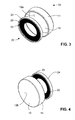
- Figs. 1 to 4 show different views of a button cover 1 according to a first embodiment of the present invention.
- Fig. 2 shows a detail view of the region marked "A" in Fig. 1.
- the button cover 1 comprises two main members, a covering member 10 and a holding member 20.
- the covering member 10 has the shape of a hollow cap, i.e., it comprises a flat cover portion 12 and a circumferential, cylindrical sidewall portion 11 extending away from the inner face 12a of the flat cover portion 12 at essentially a right angle.
- the length of the sidewall portion 11 is larger than the thickness of the button. In particular, this length is larger than the sum of the thickness of the button and the thickness of the holding member 20 described below.
- the cover portion 12 further has an ornamental outer face 12b which may be faceted or may carry precious stones or other ornaments in order to give it a pleasing appearance.
- the covering member 10 may be manufactured from any sufficiently rigid and tenacious material, such as a plastics material or a metal or metal alloy such as stainless steel, bronze, brass, silver or gold. If made from a plastics material, it may advantageously be manufactured by injection molding.
- the holding member 20 comprises a circular, ring-shaped carrier 21, a large number of bristles 22 extending inwardly from the carrier 21, and a reinforcement element 24.
- the bristles 22 are arranged on the carrier 21 in a plurality of parallel rows, in this particular example four rows, each row extending along the circumferential direction of the carrier 21.
- the free ends of the bristles 22 define a central circular opening 23.
- the bristles 22 are elastically deformable, in particular, bendable inwardly and outwardly away from the plane defined by the support 21. They are preferably manufactured from a tenacious, yet elastic material such as silicone rubber or other elastic synthetic materials.
- the bristles are formed in one piece with the ring-shaped carrier 21 made from the same material.
- This one-piece combination of a ring-shaped carrier and bristles may be called a "brush ring".
- the brush ring in itself is relatively flexible and is thus not sufficiently rigid to be used as a holding member as it is. Therefore, in order to improve stability of the holding member, the carrier 21 is surrounded by the ring-shaped reinforcement element 24 radially surrounding the carrier 21 and having inwardly extending flanges 25 on both sides of the carrier 21 for securing the carrier 21 to the reinforcement element 24.
- the reinforcement element 24 has the shape of a hollow ring which is inwardly open, similar in shape to a car tire, where the hollow inner region partially takes up the carrier 21.
- the reinforcement element 24 is manufactured from a more rigid material than the brush ring, e.g., from the same material as the covering member, in particular, a plastics material or a (sheet) metal or metal alloy.
- the carrier 21 is held in the reinforcement element 24, e.g., by clamping or by gluing. Together, the carrier 21 and the reinforcement element 24 may be regarded as serving as the support means for the bristles 22.
- the holding member 20 For mounting the button cover 1 on a button sewn to a garment by a thread, the holding member 20 is pushed over the button such that the central opening 23 encloses the thread.
- the diameter of the central opening 23 should be smaller than the diameter of the button.
- a holding member 20" which comprises a reinforcement element 24' and, clamped into the reinforcement element, a flat, thin plate or leaf 26 made from an elastic material such as spring steel or plastics.
- the plate 26 has an irregularly shaped opening 27.
- the shape of this opening 27 defines three vanes 28 protruding from the perimeter region of the holding member 20" inwardly towards its center.
- other numbers and shapes of the vanes are possible.
- the bristles or, in more general terms, the protrusions when in their normal position, extend essentially in a common plane parallel to the plane defined by the support 21 (and therefore in parallel to the inner face 12a of the covering member 10), it is also possible, e.g., that the protrusions are tilted towards the inner face 12a of the cover portion 12, the protrusions together forming an inwardly tapered configuration. It may be advantageous to "bias" the protrusions in this manner in order to increase the required force for removal of the button cover from the button.
- the entire holding element may be made in one piece from the same material, without the use of a reinforcement element 24.
- the material of the holding element should be selected to be sufficiently rigid and strong in the peripheral region while still being sufficiently elastic to ensure that the protrusions are sufficiently bendable.
- the entire holding element may be manufactured from spring steel or from an elastic synthetic material like polyethylene.
- the sidewall 11 of the covering member 10 extends along the full circumference of the cover portion 12. While this yields a pleasing aesthetic appearance, it is also possible to have, e.g., several separate sidewall portions along the circumference of the cover portion separated by slits. This may be advantageous for improving the (in its nature elastic) press fit between the covering member 10 and the holding member 20.
- the ring-shaped support 21 of the holding member 20 may be interrupted by a small gap making the holding member slightly elastically compressible radially.
- the holding member 20 may be connected to the covering member 10 by other means, e.g., by a snap-in connection well known in the art or by a screw-in type connection. While it is preferred that the holding member 20 is releasable from the covering member 10 for easy mounting, a permanent connection between these members is possible, and whole button cover may even be formed in one piece.
- the button cover has a circular shape
- various shapes of the button cover are possible, e.g., quadratic, hexagonal, octagonal, regularly or irregularly polygonal, triangular, cross-shaped, heart-shaped etc.
- the shape of the cover portion 12 of the covering member 10 may be entirely independent of the shape of the sidewall 11 and the thus-defined shape of the holding element 20.
- the button cover of the present invention may be used as part of a multifunctional, modular jewelry system.
- an adapter for the button cover may be provided.
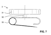
- An example for such an adapter is shown in Fig. 7.
- the adapter 3 has a button-shaped insert section 31.
- This insert section 31 is adapted for being received within a button cover according to the present invention, i.e., it preferably matches in size and shape the inside proportions of the button cover.
- a short, reduced-diameter stem section 32 is centrally connected to the insert section.
- This stem section 32 is adapted for being passed through the central opening of the holding member of the button cover which is left free by the protrusions.
- a safety pin 33 is connected to the stem section.
- the adapter 3 may be inserted into the button cover in the same manner as a button sewn to a garment, i.e., the insert section 31 replaces the button, and the stem section 32 replaces the thread.
- the button cover may thus be used as a brooch.
- the adapter 3 may comprise other kinds of connection means, e.g., an ear pin, an ear clip, a hanger for a necklace, etc.
- connection means e.g., an ear pin, an ear clip, a hanger for a necklace, etc.
- the button cover may be used as a multi-purpose jewelry item, which vastly extends the range of possible uses of the button cover.
- two button covers may be connected to form a cuff link.
- the adapter may comprise two (preferably button-shaped) insert sections connected by a stem section.
- the insert sections may also be, e.g., approximately ball-shaped, such that the overall appearance of the adapter would be bone-shaped.
- the stem may be straight or bent.
- each insert section is received in a button cover.
- the button cover according to the present invention and one or several adapters may be sold together as a multifunctional jewelry system.
Landscapes
- Adornments (AREA)
Priority Applications (1)
| Application Number | Priority Date | Filing Date | Title |
|---|---|---|---|
| EP05405404A EP1736069A1 (fr) | 2005-06-24 | 2005-06-24 | Cache-bouton |
Applications Claiming Priority (1)
| Application Number | Priority Date | Filing Date | Title |
|---|---|---|---|
| EP05405404A EP1736069A1 (fr) | 2005-06-24 | 2005-06-24 | Cache-bouton |
Publications (1)
| Publication Number | Publication Date |
|---|---|
| EP1736069A1 true EP1736069A1 (fr) | 2006-12-27 |
Family
ID=35428155
Family Applications (1)
| Application Number | Title | Priority Date | Filing Date |
|---|---|---|---|
| EP05405404A Withdrawn EP1736069A1 (fr) | 2005-06-24 | 2005-06-24 | Cache-bouton |
Country Status (1)
| Country | Link |
|---|---|
| EP (1) | EP1736069A1 (fr) |
Cited By (2)
| Publication number | Priority date | Publication date | Assignee | Title |
|---|---|---|---|---|
| DE102013108479A1 (de) * | 2013-08-06 | 2015-02-12 | Daniel Antonio Moral | Lösbare Knopfabdeckung |
| FR3127868A1 (fr) * | 2021-10-13 | 2023-04-14 | Etienne CONSTANT | Clip cache-bouton |
Citations (5)
| Publication number | Priority date | Publication date | Assignee | Title |
|---|---|---|---|---|
| US2189467A (en) * | 1937-12-22 | 1940-02-06 | Jacobs Abraham | Ornament and button shield |
| CH250979A (de) * | 1945-11-08 | 1947-09-30 | Buergin & Cie Gmbh | Knopf. |
| US3777336A (en) | 1972-09-14 | 1973-12-11 | Anson Inc | Button cover |
| FR2582919A1 (fr) * | 1985-06-11 | 1986-12-12 | Trommetter Henri | Clip decoratif amovible pour bouton de vetement, notamment un bouton de poignet de chemise. |
| US5033168A (en) | 1989-11-06 | 1991-07-23 | Luca Sbragi | Button cover with slidable fastening member |
-
2005
- 2005-06-24 EP EP05405404A patent/EP1736069A1/fr not_active Withdrawn
Patent Citations (5)
| Publication number | Priority date | Publication date | Assignee | Title |
|---|---|---|---|---|
| US2189467A (en) * | 1937-12-22 | 1940-02-06 | Jacobs Abraham | Ornament and button shield |
| CH250979A (de) * | 1945-11-08 | 1947-09-30 | Buergin & Cie Gmbh | Knopf. |
| US3777336A (en) | 1972-09-14 | 1973-12-11 | Anson Inc | Button cover |
| FR2582919A1 (fr) * | 1985-06-11 | 1986-12-12 | Trommetter Henri | Clip decoratif amovible pour bouton de vetement, notamment un bouton de poignet de chemise. |
| US5033168A (en) | 1989-11-06 | 1991-07-23 | Luca Sbragi | Button cover with slidable fastening member |
Cited By (3)
| Publication number | Priority date | Publication date | Assignee | Title |
|---|---|---|---|---|
| DE102013108479A1 (de) * | 2013-08-06 | 2015-02-12 | Daniel Antonio Moral | Lösbare Knopfabdeckung |
| DE102013108479B4 (de) * | 2013-08-06 | 2017-08-24 | Daniel Antonio Moral | Lösbare Knopfabdeckung |
| FR3127868A1 (fr) * | 2021-10-13 | 2023-04-14 | Etienne CONSTANT | Clip cache-bouton |
Similar Documents
| Publication | Publication Date | Title |
|---|---|---|
| US6675446B2 (en) | Attachable neck lanyard slider | |
| US6484537B2 (en) | Replaceable gem stone setting for a jewelry piece | |
| US6675611B2 (en) | Necklace mount | |
| US4569211A (en) | Finger ring and insert therefor | |
| CA2294932C (fr) | Bijou pour body piercing | |
| EP0456381A1 (fr) | Ornements pendants pour lunettes | |
| US20150282575A1 (en) | System and method for securing accessories to jewelry | |
| EP1304943B1 (fr) | Element ornemental pour un systeme de bijouterie et systeme de bijouterie comprenant ledit element ornemental | |
| US5369854A (en) | Necklace clasp | |
| JP2006288484A (ja) | 健康リストバンド | |
| US4891956A (en) | Indicia device | |
| CN107656432B (zh) | 用于钟表或珠宝饰品的外部部件的子组件 | |
| EP1942762B1 (fr) | Insigne pouvant être fixé à des vêtements par bouton-pression et vêtement muni de boutons-pression | |
| KR102249344B1 (ko) | 귀찌형 귀걸이 | |
| US8201417B1 (en) | Jewelry mount with safety catch | |
| CN208114159U (zh) | 一种镶嵌基座及首饰 | |
| CN101150968A (zh) | 自锁连接装置 | |
| CN1784155A (zh) | 外形可变的环 | |
| EP2838397A1 (fr) | Système d'accouplement pour boucles d'oreilles en métal précieux | |
| EP1916921B1 (fr) | Incrustation de bijou interchangeable et article de reception de l'incrustation | |
| WO2008017396A1 (fr) | Fermoirs de sécurité et moyens de connexion pour articles ornementaux | |
| JP3147796U (ja) | 装身具の装飾体 | |
| CN208114161U (zh) | 一种镶嵌基座及首饰 | |
| KR101828755B1 (ko) | 귀걸이 고정구 | |
| CN216601887U (zh) | 一种弹力手镯 |
Legal Events
| Date | Code | Title | Description |
|---|---|---|---|
| PUAI | Public reference made under article 153(3) epc to a published international application that has entered the european phase |
Free format text: ORIGINAL CODE: 0009012 |
|
| AK | Designated contracting states |
Kind code of ref document: A1 Designated state(s): AT BE BG CH CY CZ DE DK EE ES FI FR GB GR HU IE IS IT LI LT LU MC NL PL PT RO SE SI SK TR |
|
| AX | Request for extension of the european patent |
Extension state: AL BA HR LV MK YU |
|
| AKX | Designation fees paid | ||
| REG | Reference to a national code |
Ref country code: DE Ref legal event code: 8566 |
|
| STAA | Information on the status of an ep patent application or granted ep patent |
Free format text: STATUS: THE APPLICATION IS DEEMED TO BE WITHDRAWN |
|
| 18D | Application deemed to be withdrawn |
Effective date: 20070628 |