EP1736264A1 - Dispositif pour l'usinage intérieur de pièces, en particulier de carters d'engrenages différentiels - Google Patents
Dispositif pour l'usinage intérieur de pièces, en particulier de carters d'engrenages différentiels Download PDFInfo
- Publication number
- EP1736264A1 EP1736264A1 EP06011953A EP06011953A EP1736264A1 EP 1736264 A1 EP1736264 A1 EP 1736264A1 EP 06011953 A EP06011953 A EP 06011953A EP 06011953 A EP06011953 A EP 06011953A EP 1736264 A1 EP1736264 A1 EP 1736264A1
- Authority
- EP
- European Patent Office
- Prior art keywords
- tool
- machining
- workpiece
- spindle
- tools
- Prior art date
- Legal status (The legal status is an assumption and is not a legal conclusion. Google has not performed a legal analysis and makes no representation as to the accuracy of the status listed.)
- Granted
Links
- 238000003754 machining Methods 0.000 title claims description 67
- 238000012545 processing Methods 0.000 claims description 56
- 238000012546 transfer Methods 0.000 claims description 10
- 230000008878 coupling Effects 0.000 claims description 6
- 238000010168 coupling process Methods 0.000 claims description 6
- 238000005859 coupling reaction Methods 0.000 claims description 6
- 238000004140 cleaning Methods 0.000 claims description 2
- 238000001816 cooling Methods 0.000 claims description 2
- 230000001050 lubricating effect Effects 0.000 claims description 2
- 238000013461 design Methods 0.000 description 3
- 238000003860 storage Methods 0.000 description 3
- 238000006243 chemical reaction Methods 0.000 description 2
- 238000011161 development Methods 0.000 description 2
- 230000018109 developmental process Effects 0.000 description 2
- 238000004519 manufacturing process Methods 0.000 description 2
- 241000985128 Cladium mariscus Species 0.000 description 1
- 230000015572 biosynthetic process Effects 0.000 description 1
- 230000000295 complement effect Effects 0.000 description 1
- 238000005520 cutting process Methods 0.000 description 1
- 230000003247 decreasing effect Effects 0.000 description 1
- 230000001419 dependent effect Effects 0.000 description 1
- 238000000034 method Methods 0.000 description 1
- 238000003801 milling Methods 0.000 description 1
- NJPPVKZQTLUDBO-UHFFFAOYSA-N novaluron Chemical compound C1=C(Cl)C(OC(F)(F)C(OC(F)(F)F)F)=CC=C1NC(=O)NC(=O)C1=C(F)C=CC=C1F NJPPVKZQTLUDBO-UHFFFAOYSA-N 0.000 description 1
- 230000002093 peripheral effect Effects 0.000 description 1
Images



Classifications
-
- B—PERFORMING OPERATIONS; TRANSPORTING
- B23—MACHINE TOOLS; METAL-WORKING NOT OTHERWISE PROVIDED FOR
- B23Q—DETAILS, COMPONENTS, OR ACCESSORIES FOR MACHINE TOOLS, e.g. ARRANGEMENTS FOR COPYING OR CONTROLLING; MACHINE TOOLS IN GENERAL CHARACTERISED BY THE CONSTRUCTION OF PARTICULAR DETAILS OR COMPONENTS; COMBINATIONS OR ASSOCIATIONS OF METAL-WORKING MACHINES, NOT DIRECTED TO A PARTICULAR RESULT
- B23Q3/00—Devices holding, supporting, or positioning work or tools, of a kind normally removable from the machine
- B23Q3/155—Arrangements for automatic insertion or removal of tools, e.g. combined with manual handling
- B23Q3/1552—Arrangements for automatic insertion or removal of tools, e.g. combined with manual handling parts of devices for automatically inserting or removing tools
- B23Q3/15526—Storage devices; Drive mechanisms therefor
- B23Q3/15539—Plural magazines, e.g. involving tool transfer from one magazine to another
-
- B—PERFORMING OPERATIONS; TRANSPORTING
- B23—MACHINE TOOLS; METAL-WORKING NOT OTHERWISE PROVIDED FOR
- B23B—TURNING; BORING
- B23B41/00—Boring or drilling machines or devices specially adapted for particular work; Accessories specially adapted therefor
- B23B41/12—Boring or drilling machines or devices specially adapted for particular work; Accessories specially adapted therefor for forming working surfaces of cylinders, of bearings, e.g. in heads of driving rods, or of other engine parts
-
- B—PERFORMING OPERATIONS; TRANSPORTING
- B23—MACHINE TOOLS; METAL-WORKING NOT OTHERWISE PROVIDED FOR
- B23B—TURNING; BORING
- B23B41/00—Boring or drilling machines or devices specially adapted for particular work; Accessories specially adapted therefor
- B23B41/06—Boring or drilling machines or devices specially adapted for particular work; Accessories specially adapted therefor for boring conical holes
-
- B—PERFORMING OPERATIONS; TRANSPORTING
- B23—MACHINE TOOLS; METAL-WORKING NOT OTHERWISE PROVIDED FOR
- B23Q—DETAILS, COMPONENTS, OR ACCESSORIES FOR MACHINE TOOLS, e.g. ARRANGEMENTS FOR COPYING OR CONTROLLING; MACHINE TOOLS IN GENERAL CHARACTERISED BY THE CONSTRUCTION OF PARTICULAR DETAILS OR COMPONENTS; COMBINATIONS OR ASSOCIATIONS OF METAL-WORKING MACHINES, NOT DIRECTED TO A PARTICULAR RESULT
- B23Q3/00—Devices holding, supporting, or positioning work or tools, of a kind normally removable from the machine
- B23Q3/155—Arrangements for automatic insertion or removal of tools, e.g. combined with manual handling
- B23Q3/157—Arrangements for automatic insertion or removal of tools, e.g. combined with manual handling of rotary tools
- B23Q3/15706—Arrangements for automatic insertion or removal of tools, e.g. combined with manual handling of rotary tools a single tool being inserted in a spindle directly from a storage device, i.e. without using transfer devices
-
- B—PERFORMING OPERATIONS; TRANSPORTING
- B23—MACHINE TOOLS; METAL-WORKING NOT OTHERWISE PROVIDED FOR
- B23Q—DETAILS, COMPONENTS, OR ACCESSORIES FOR MACHINE TOOLS, e.g. ARRANGEMENTS FOR COPYING OR CONTROLLING; MACHINE TOOLS IN GENERAL CHARACTERISED BY THE CONSTRUCTION OF PARTICULAR DETAILS OR COMPONENTS; COMBINATIONS OR ASSOCIATIONS OF METAL-WORKING MACHINES, NOT DIRECTED TO A PARTICULAR RESULT
- B23Q3/00—Devices holding, supporting, or positioning work or tools, of a kind normally removable from the machine
- B23Q3/155—Arrangements for automatic insertion or removal of tools, e.g. combined with manual handling
- B23Q3/1552—Arrangements for automatic insertion or removal of tools, e.g. combined with manual handling parts of devices for automatically inserting or removing tools
- B23Q3/15526—Storage devices; Drive mechanisms therefor
- B23Q2003/15537—Linearly moving storage devices
Definitions
- the invention relates to a device for machining workpieces, in particular for the internal machining of differential gear housings or other housings.
- differential gear housing which represent a hollow body in the basic form, which must be processed both outside and inside.
- the differential housings of the second known type are more complex in the interior. They have different contours inside, consisting of spherical caps, holes, countersinks and the like.
- a gripper In order to produce these mold elements with high accuracy, it is necessary that successively different milling and lowering tools are retracted by a gripper into the workpiece interior on different stations.
- a suitable tool By means of at least one machining spindle, on which a guide pin is arranged, a suitable tool can be received. If two opposing machining spindles provided, it is possible to thread the tool on a mandrel or both by axial delivery of the spindles or clamping dome and to clamp axially with the other dome.
- the tensioning domes have a torque entrainment, for example in the form of a splined profile for the tool on.
- the machining in the interior is carried out in that the one spindle or both spindles are moved together in the spindle longitudinal direction. Because of the very tight space conditions dictated by the workpiece, different internal machining tools with different grippers and different clamping domes are required.
- the invention has the object of providing a device with the features of the preamble of claim 1 in such a way that it can be processed without great spatial complexity and very complex internal structures of workpieces of the type in question, with different automatic changeable in only one processing station Tools are to be used, the capacity of the machine should be easily adaptable to a different processing needs.
- the core of the invention it is considered to arrange both a first and a second tool magazine in the region of the at least one processing station.
- the first tool magazine contains a plurality of machining tools and / or guide tools for interior tools.
- the processing tools of the first tool magazine are mainly used for external machining of the workpiece, the guide domes are adapted to accommodate interior tools that are included in the other tool magazine.
- the second tool magazine mainly contains internal processing tools of different types, which can be introduced from the tool magazine or through this through an opening of the workpiece in the interior and there by at least one further opening of the workpiece by cross-clamping dome are fixed.
- tool magazines When talking about tool magazines in the context of the invention, it is understood that such a tool magazine may contain at least six, but advantageously also significantly more, different outer and inner machining tools or guide pins for inner tools in order to be able to cope with the various machining tasks.
- the two magazines lie next to each other and complement each other in terms of guide domes and interior tools.
- the tool change can easily be made by the device easily.
- a particular advantage of the device is that internal and external machining steps can be performed on one and the same processing station.
- the external machining can be tolerated with high precision to the internal structure of the workpiece, which is e.g. in view of the axbox of a differential gear housing is of particular importance.
- the second tool magazine is arranged centrally or centrally above the clamped workpiece.
- the tools can then be inserted through a simple downwardly directed movement of a tool holding arm or the like, or through an overall movement of the magazine down into the interior of the workpiece through an upwardly facing opening.
- the tool magazine which advantageously has a rotatable tool holding disc or a rotatable tool holding star, at the same height with the clamped workpiece and to place the corresponding tools in the inner region of the workpiece by substantially horizontally extending constitutionalzustellierien.
- a second spindle is present in the processing area.
- a third tool magazine is arranged, e.g. Guide dome and external machining tools corresponding to the first tool magazine may contain.
- a rotary table is arranged on the machine frame, which is rotatable about a vertically extending axis and on which the clamping device is mounted for receiving the workpiece.
- the rotary table can be moved between the processing area and a loading station.
- the machining spindles of a machining area are aligned with one another or can be brought at least into a mutually aligned machining position. This includes that the carriages which carry the machining spindles can not only be delivered to the workpiece, but can be displaced or moved in at least one plane which runs at right angles to the spindle longitudinal axis. This results in even more diverse editing options.
- the rotary table can be arranged at right angles to the longitudinal axis of the machining spindle movable on the machine frame. By moving the rotary table, which is by definition rotatable about its vertical axis, the workpiece can be brought into any position to the machining spindles. As a result, the processing options in the outer and inner regions of the workpiece are further improved.
- the invention In order not to have to stop the machining process required magazine upgrades, it is advantageously possible in the invention to move the tool magazines from a working position on the workpieces or the processing stations in at least one conversion position. Basically, it is possible per processing area with two spindles not only the invention three To provide tool magazine, but for example, two more, which are in a retool parking position and can be replaced very quickly by inserting into the processing area against tool magazines with other tools or worn tools.
- the tool magazines are held movably above the machine frame on at least one guide arrangement.
- the tool magazines may in principle be of star-shaped design, ie. in a plane around a rotation axis are star-shaped e.g. arranged six or eight tools, which are due to their Stem arrangement in the inner region of the workpiece or on an outer region of the workpiece on or brought up.
- a tool magazine according to the invention disc-shaped, in particular with a tool carrier disc on which the tools radially displaceable tool arms are arranged and at least one motor driven tool conveyor element is provided, which is arranged on a tool arm tool from a radially inner parking position into a radially outer transfer position can move, then far more than six or eight tools can be arranged on or in such a tool magazine.
- the radially outer transfer position corresponds to the position in which a coupling element of a machining spindle has received or received the tool. This position can also be referred to as the working position of the tool.
- the tool carrier disc provided with the radial guides or slots has a motorized rotary drive connected by a control device connected to the device. All delivery and processing movements of the device are monitored or controlled by this control device in a conventional manner.
- the tool holding arms which are arranged on the tool carrier disc, are guided with sliding elements in radial slots or on the radial guides of the tool holding disc.
- Parallel to the tool carrier disc can be provided with an annular groove provided non-rotatable counter-pulley with advantage, wherein the annular groove is provided with an opening extending to the processing position.
- parking position of the tools ie in the retracted radially inner position is in each case a driving element of the tool holding arms in the annular groove, so that centrifugal forces can be reliably collected during rotation of the disc.
- Upon rotation of the tool carrier disk run the entrainment of the tool holding arms in the annular groove of the counter-disc.
- the arranged on the support plate tool conveyor element has a gripping element, with which it engages in a radially inner receiving position a driving element of the tool holding arms and thereby can move it in the direction of the transfer position.
- a tool conveying element for all tools of a magazine, in a further development of the invention, however, separate tool conveying devices can be provided on the tool carrier disk for each tool holding arm.
- the driving elements are advantageously designed as cam rollers, which roll in rotation of the tool carrier disc in the annular groove.
- the annular groove has an opening which can be closed by a slider during rotation of the tool carrier disk, so that the driving elements (cam rollers) can rotate without interference in the tool carrier disk. If a tool is to be extended out of the magazine, then the opening of the annular groove is opened by the slide and a tool holding arm can leave the annular groove of the counter disk with its driving element, whereby it can be extended in the direction of the workpiece.
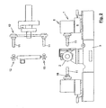
- the device 1 for machining workpieces 2 has a machine frame 3, on which a clamping device 4 for receiving the workpiece is arranged.
- a processing station 5 is provided which comprises at least one deliverable against the clamped workpiece 2, arranged on a carriage 6 motor-driven machining spindle 7, which edit 9 by means of a arranged at its free end 8 tool inside and outside areas of the workpiece 2 can.
- a first tool magazine 10 is arranged, in or on which a plurality of machining tools 9 and / or guide pins 11 are received for different machining tools.
- the first tool magazine can be moved in whole or in part to the machining spindle 7 in order to place machining tools 9 or guide pins 11 on the machining spindle 7.
- a second tool magazine 12 is disposed above the processing station 5, are contained in or on which internal processing tools 13 which are inserted from the tool magazine 12 or through this itself through an opening 14 of the workpiece 2 in its interior 15. There, they are received and fixed by a further opening 16 by cross-guide mandrel 11, so that with this guide mandrel / tool constellation by means of the first spindle, the internal machining of the workpiece 2 can be made.
- the second tool magazine 12 is arranged centrally above the clamped workpiece 2, so that a simple downward movement of the tool magazine or a tool holding element, the tool 9 can be retracted into the interior 15 of the tool.
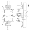
- FIG. 2 includes the Processing station 5 a second machining spindle 18. If a third tool magazine 19 is mounted above the second machining spindle 18, guide pins 11 of different types can also be arranged and exchanged on the second machining spindle and external machining tools can also be mounted in the area of the second machining spindle 18.
- a rotary table 20 is arranged, which can be rotated about a vertical axis 21, the so-called B-axis.
- the rotary table 20 is mounted on a carriage 22 mounted on guide elements 23, e.g. a prism bed perpendicular to the longitudinal direction of the machining spindles, i. in the X direction between a processing position 24 and a loading station 25 can be moved.
- the clamping device 4 for receiving the workpiece 2 is arranged on the rotary table 20, so that the workpiece 2 is both linearly displaceable and rotatable. In principle, it is also possible to raise or lower the rotary table 20 so that complex machining patterns can also be processed via the machining spindles on the workpiece 2.
- the tensioning device 4 comprises clamping prisms, which can safely clamp even complex workpieces with a shape approximated by a ball.
- machine frame 3 in an extended form, so that a plurality of rotary tables 20 with a corresponding plurality of loading stations 25 can be provided on a machine frame.
- Each processing spindle 7 is mounted on a deliverable to the workpiece 2 processing carriage 26.
- the feed direction of the processing carriage 26 is referred to as Z-axis.
- the machining spindles 7 with the machining carriage 26 also to be in the vertical direction, i. movable in Y-axis.
- tool magazines are arranged above the processing station 5 or the processing stations, which will now be discussed in more detail.
- the first tool magazine 10 and the third tool magazine 19 may be formed substantially identically, meaning that their formation permits the placement of acceptable guide domes 11 and external machining tools.
- All tool magazines 10, 12 and 19 can be delivered to the workpiece 2 either as a whole or areas or arms of the tool magazines extend out of the rotatably arranged tool magazines and thus set the selected processing tool 9 on or in the workpiece, so that the machining spindle 7 can record and rotationally fix the tool with a correspondingly selected guide pin.
- the tool magazines 10, 12 and 19 are disc-shaped or stem-like and preferably arranged in parallel.
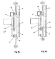
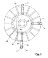
- the second tool magazine 12 has a tool carrier disk 32 provided with radial slots or other guides 31, on which the machining tools 9 are arranged on radially displaceable tool holding elements 17 in the form of tool arms 33.
- at least one motor-driven tool conveying element 34 is provided which moves a machining tool 9 arranged on a tool arm 33 from a radially inner parking position (FIG. 4b) into a radially outer transfer position (FIG. 4a).
- the machining tool 9 is arranged in a machining position aligned with the machining spindles 7, 18 and is received by a coupling element of a machining spindle or a guide dome 11.
- the tool carrier disk 32 provided with the radial slots or guides 31 is motor-rotatably and can be moved into a specific selection transfer position via an electronic machine control.
- the tool holding arms 33 are guided with sliding elements 35 in the radial guides 31 of the tool holding disc 32.
- a non-rotatable counter disk 37 provided with an annular groove 36 is arranged parallel to the tool carrier disk 32, wherein the annular groove 36 is provided with an aperture 38 extending to the processing position.
- Driving elements 40 which cooperate with the sliding elements 35 of the tool holding arms, are arranged in the parking position of the processing tools 9 in the annular groove 36.
- a claw-like movable gate segment 41 of the tool conveying element 34 is arranged in the opening 38, so that circumferential driving elements 40 can pass through the gate segment.
- the conveying element consists essentially of a compressed air cylinder 45 which is fixed on the counter-plate 37 and from the lower end 46, a piston rod 47 is extendable, which carries the movable link segment 41 at its lower end.
- a piston rod 47 is extendable, which carries the movable link segment 41 at its lower end.
- only three tool holding arms are shown in drawing FIG. At their radially outer ends, the tool holding arms 33 carry grippers 50 which are suitable for receiving and delivering the tools 9.
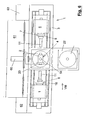
- FIG. 6 once again shows the walk-in pedestal 61 with an operator who performs work on a tool magazine 12 by means of a closable opening of a housing around the processing area.
- FIG. 8 also shows a round pallet storage 70 which can be used in conjunction with the device 1.
- a linear pallet memory 80 is indicated in connection with the device 1.
Landscapes
- Engineering & Computer Science (AREA)
- Mechanical Engineering (AREA)
- Automatic Tool Replacement In Machine Tools (AREA)
- Retarders (AREA)
- Gear Processing (AREA)
Applications Claiming Priority (1)
| Application Number | Priority Date | Filing Date | Title |
|---|---|---|---|
| DE102005029620A DE102005029620B4 (de) | 2005-06-23 | 2005-06-23 | Vorrichtung zur Bearbeitung von Werkstücken, insbesondere zur Innenbearbeitung von Differentialgetriebegehäusen oder sonstigen Getriebegehäusen |
Publications (2)
| Publication Number | Publication Date |
|---|---|
| EP1736264A1 true EP1736264A1 (fr) | 2006-12-27 |
| EP1736264B1 EP1736264B1 (fr) | 2008-08-13 |
Family
ID=37055946
Family Applications (1)
| Application Number | Title | Priority Date | Filing Date |
|---|---|---|---|
| EP06011953A Not-in-force EP1736264B1 (fr) | 2005-06-23 | 2006-06-09 | Dispositif pour l'usinage intérieur de pièces, en particulier de carters d'engrenages différentiels |
Country Status (3)
| Country | Link |
|---|---|
| EP (1) | EP1736264B1 (fr) |
| AT (1) | ATE404312T1 (fr) |
| DE (2) | DE102005029620B4 (fr) |
Cited By (9)
| Publication number | Priority date | Publication date | Assignee | Title |
|---|---|---|---|---|
| CN105345532A (zh) * | 2015-11-27 | 2016-02-24 | 芜湖银星汽车零部件有限公司 | 一种差速器腔体加工夹具 |
| CN107717580A (zh) * | 2017-11-09 | 2018-02-23 | 王海艳 | 一种用于加工差速器十字轴的夹具 |
| CN108000399A (zh) * | 2017-12-27 | 2018-05-08 | 重庆英拓机电设备有限公司 | 一种用于差速器生产的定位装置 |
| CN109352410A (zh) * | 2018-11-20 | 2019-02-19 | 新昌县奔力机械有限公司 | 一种快速更换式夹具安装平台 |
| CN110000401A (zh) * | 2019-05-14 | 2019-07-12 | 福州大学 | 基于自动线中加工零件端面用的横向进刀机构及其工作方法 |
| CN110153766A (zh) * | 2019-06-05 | 2019-08-23 | 三星智能科技盐城有限公司 | 一种带清洁换刀系统的数控机床 |
| CN113814914A (zh) * | 2021-11-02 | 2021-12-21 | 重庆德卡汽车零部件制造有限公司 | 一种汽车差速器壳体加工夹具 |
| CN116619064A (zh) * | 2022-07-07 | 2023-08-22 | 江苏威马悦达智能装备有限公司 | 一种大型零部件双主轴加工设备及其工作方法 |
| CN117840485A (zh) * | 2024-03-06 | 2024-04-09 | 南通市联福机械科技有限公司 | 一种轴承座铸件成型加工设备 |
Citations (3)
| Publication number | Priority date | Publication date | Assignee | Title |
|---|---|---|---|---|
| DE19716491A1 (de) * | 1997-04-19 | 1998-10-22 | Chiron Werke Gmbh | Werkzeugmaschine zur Bearbeitung von Werkstückhohlräumen |
| US20030049086A1 (en) * | 2001-09-11 | 2003-03-13 | Cavanaugh Brian M. | Internal cavity cutting tool with stable support |
| US20040226154A1 (en) * | 2003-02-24 | 2004-11-18 | Emag Maschinenfabrik Gmbh | Machining differential housings |
Family Cites Families (2)
| Publication number | Priority date | Publication date | Assignee | Title |
|---|---|---|---|---|
| DE3722180C2 (de) * | 1987-07-04 | 1994-07-07 | Giddings & Lewis Gmbh | Transfermaschine |
| FR2699100B1 (fr) * | 1992-12-15 | 1995-03-10 | Helis Sa | Machine-outil équipée d'un magasin d'outils à disques. |
-
2005
- 2005-06-23 DE DE102005029620A patent/DE102005029620B4/de not_active Expired - Fee Related
-
2006
- 2006-06-09 AT AT06011953T patent/ATE404312T1/de not_active IP Right Cessation
- 2006-06-09 EP EP06011953A patent/EP1736264B1/fr not_active Not-in-force
- 2006-06-09 DE DE502006001305T patent/DE502006001305D1/de active Active
Patent Citations (3)
| Publication number | Priority date | Publication date | Assignee | Title |
|---|---|---|---|---|
| DE19716491A1 (de) * | 1997-04-19 | 1998-10-22 | Chiron Werke Gmbh | Werkzeugmaschine zur Bearbeitung von Werkstückhohlräumen |
| US20030049086A1 (en) * | 2001-09-11 | 2003-03-13 | Cavanaugh Brian M. | Internal cavity cutting tool with stable support |
| US20040226154A1 (en) * | 2003-02-24 | 2004-11-18 | Emag Maschinenfabrik Gmbh | Machining differential housings |
Cited By (13)
| Publication number | Priority date | Publication date | Assignee | Title |
|---|---|---|---|---|
| CN105345532A (zh) * | 2015-11-27 | 2016-02-24 | 芜湖银星汽车零部件有限公司 | 一种差速器腔体加工夹具 |
| CN107717580A (zh) * | 2017-11-09 | 2018-02-23 | 王海艳 | 一种用于加工差速器十字轴的夹具 |
| CN108000399A (zh) * | 2017-12-27 | 2018-05-08 | 重庆英拓机电设备有限公司 | 一种用于差速器生产的定位装置 |
| CN109352410B (zh) * | 2018-11-20 | 2023-08-25 | 广东德信模钢实业有限公司 | 一种快速更换式夹具安装平台 |
| CN109352410A (zh) * | 2018-11-20 | 2019-02-19 | 新昌县奔力机械有限公司 | 一种快速更换式夹具安装平台 |
| CN110000401A (zh) * | 2019-05-14 | 2019-07-12 | 福州大学 | 基于自动线中加工零件端面用的横向进刀机构及其工作方法 |
| CN110153766A (zh) * | 2019-06-05 | 2019-08-23 | 三星智能科技盐城有限公司 | 一种带清洁换刀系统的数控机床 |
| CN110153766B (zh) * | 2019-06-05 | 2024-01-30 | 三星智能科技盐城有限公司 | 一种带清洁换刀系统的数控机床 |
| CN113814914A (zh) * | 2021-11-02 | 2021-12-21 | 重庆德卡汽车零部件制造有限公司 | 一种汽车差速器壳体加工夹具 |
| CN116619064B (zh) * | 2022-07-07 | 2023-12-05 | 江苏威马悦达智能装备有限公司 | 一种大型零部件双主轴加工设备及其工作方法 |
| CN116619064A (zh) * | 2022-07-07 | 2023-08-22 | 江苏威马悦达智能装备有限公司 | 一种大型零部件双主轴加工设备及其工作方法 |
| CN117840485A (zh) * | 2024-03-06 | 2024-04-09 | 南通市联福机械科技有限公司 | 一种轴承座铸件成型加工设备 |
| CN117840485B (zh) * | 2024-03-06 | 2024-05-03 | 南通市联福机械科技有限公司 | 一种轴承座铸件成型加工设备 |
Also Published As
| Publication number | Publication date |
|---|---|
| DE502006001305D1 (de) | 2008-09-25 |
| EP1736264B1 (fr) | 2008-08-13 |
| ATE404312T1 (de) | 2008-08-15 |
| DE102005029620B4 (de) | 2011-06-01 |
| DE102005029620A1 (de) | 2006-12-28 |
Similar Documents
| Publication | Publication Date | Title |
|---|---|---|
| EP1765550B1 (fr) | Machine-outil | |
| DE3035451C2 (fr) | ||
| EP3195977B1 (fr) | Machine-outil, en particulier fraiseuse multibroche | |
| DE69127513T2 (de) | Palettenspeicher- und Palettenwechselvorrichtung für WZM und Drehbank mit automatisch auswechselbaren Paletten | |
| DE3427245C2 (de) | Werkzeugmaschine | |
| EP1886763B1 (fr) | Magasin d'outils pour machine-outil | |
| EP3195976B1 (fr) | Machine-outil, en particulier fraiseuse multibroche | |
| DE19521846A1 (de) | Numerisch gesteuerte Bearbeitungsmaschine | |
| EP3147073A1 (fr) | Machine-outil, en particulier fraiseuse multi-broches | |
| WO1993007981A1 (fr) | Tour | |
| DE4446963A1 (de) | Programmgesteuerte Werkzeugmaschine mit automatisiertem Werkzeugwechsel | |
| EP2060359A2 (fr) | Affûteuse | |
| EP0885686B1 (fr) | Centre d'usinage | |
| EP3412403B1 (fr) | Machine-outil destinée à l'usinage par enlèvement de copeaux d'une pièce à usiner | |
| EP1718435B1 (fr) | Machine d'usinage pour usiner des pieces | |
| DE19904859A1 (de) | Drehmaschine mit zwei Werkstückspindeln | |
| EP0260692B1 (fr) | Machine-outil avec un porte-broche à forer et à fraiser à déplacement dans la direction Z sur un châssis de machine | |
| EP1736264B1 (fr) | Dispositif pour l'usinage intérieur de pièces, en particulier de carters d'engrenages différentiels | |
| DE10307977C5 (de) | Verfahren und Vorrichtung zur Bearbeitung von Ausgleichsgehäusen | |
| WO2021028205A1 (fr) | Machine de perçage en profondeur | |
| DE102006042006B4 (de) | Drehmaschine | |
| EP0137117B1 (fr) | Dispositif changeur d'outils comprenant un appareil pour le transfert des têtes d'outils | |
| EP3250341B1 (fr) | Procédé, en particulier de fabrication flexible plus efficace de modèles d'usinage au moyen de plusieurs axes | |
| DE3330653A1 (de) | Revolverdrehautomat bzw. nc-drehmaschine mit einem radial geteilten werkzeugrevolverkopf | |
| DE2429330A1 (de) | Programmgesteuerte werkzeugmaschine |
Legal Events
| Date | Code | Title | Description |
|---|---|---|---|
| PUAI | Public reference made under article 153(3) epc to a published international application that has entered the european phase |
Free format text: ORIGINAL CODE: 0009012 |
|
| AK | Designated contracting states |
Kind code of ref document: A1 Designated state(s): AT BE BG CH CY CZ DE DK EE ES FI FR GB GR HU IE IS IT LI LT LU LV MC NL PL PT RO SE SI SK TR |
|
| AX | Request for extension of the european patent |
Extension state: AL BA HR MK YU |
|
| 17P | Request for examination filed |
Effective date: 20070223 |
|
| 17Q | First examination report despatched |
Effective date: 20070322 |
|
| RAP1 | Party data changed (applicant data changed or rights of an application transferred) |
Owner name: WEMA VOGTLAND GMBH |
|
| AKX | Designation fees paid |
Designated state(s): AT BE BG CH CY CZ DE DK EE ES FI FR GB GR HU IE IS IT LI LT LU LV MC NL PL PT RO SE SI SK TR |
|
| GRAP | Despatch of communication of intention to grant a patent |
Free format text: ORIGINAL CODE: EPIDOSNIGR1 |
|
| GRAS | Grant fee paid |
Free format text: ORIGINAL CODE: EPIDOSNIGR3 |
|
| GRAA | (expected) grant |
Free format text: ORIGINAL CODE: 0009210 |
|
| AK | Designated contracting states |
Kind code of ref document: B1 Designated state(s): AT BE BG CH CY CZ DE DK EE ES FI FR GB GR HU IE IS IT LI LT LU LV MC NL PL PT RO SE SI SK TR |
|
| REG | Reference to a national code |
Ref country code: GB Ref legal event code: FG4D Free format text: NOT ENGLISH |
|
| REG | Reference to a national code |
Ref country code: CH Ref legal event code: EP |
|
| REG | Reference to a national code |
Ref country code: IE Ref legal event code: FG4D Free format text: LANGUAGE OF EP DOCUMENT: GERMAN |
|
| REF | Corresponds to: |
Ref document number: 502006001305 Country of ref document: DE Date of ref document: 20080925 Kind code of ref document: P |
|
| PG25 | Lapsed in a contracting state [announced via postgrant information from national office to epo] |
Ref country code: LT Free format text: LAPSE BECAUSE OF FAILURE TO SUBMIT A TRANSLATION OF THE DESCRIPTION OR TO PAY THE FEE WITHIN THE PRESCRIBED TIME-LIMIT Effective date: 20080813 Ref country code: IS Free format text: LAPSE BECAUSE OF FAILURE TO SUBMIT A TRANSLATION OF THE DESCRIPTION OR TO PAY THE FEE WITHIN THE PRESCRIBED TIME-LIMIT Effective date: 20081213 Ref country code: NL Free format text: LAPSE BECAUSE OF FAILURE TO SUBMIT A TRANSLATION OF THE DESCRIPTION OR TO PAY THE FEE WITHIN THE PRESCRIBED TIME-LIMIT Effective date: 20080813 |
|
| PG25 | Lapsed in a contracting state [announced via postgrant information from national office to epo] |
Ref country code: FI Free format text: LAPSE BECAUSE OF FAILURE TO SUBMIT A TRANSLATION OF THE DESCRIPTION OR TO PAY THE FEE WITHIN THE PRESCRIBED TIME-LIMIT Effective date: 20080813 Ref country code: SI Free format text: LAPSE BECAUSE OF FAILURE TO SUBMIT A TRANSLATION OF THE DESCRIPTION OR TO PAY THE FEE WITHIN THE PRESCRIBED TIME-LIMIT Effective date: 20080813 Ref country code: LV Free format text: LAPSE BECAUSE OF FAILURE TO SUBMIT A TRANSLATION OF THE DESCRIPTION OR TO PAY THE FEE WITHIN THE PRESCRIBED TIME-LIMIT Effective date: 20080813 Ref country code: ES Free format text: LAPSE BECAUSE OF FAILURE TO SUBMIT A TRANSLATION OF THE DESCRIPTION OR TO PAY THE FEE WITHIN THE PRESCRIBED TIME-LIMIT Effective date: 20081124 |
|
| REG | Reference to a national code |
Ref country code: IE Ref legal event code: FD4D |
|
| PG25 | Lapsed in a contracting state [announced via postgrant information from national office to epo] |
Ref country code: IE Free format text: LAPSE BECAUSE OF FAILURE TO SUBMIT A TRANSLATION OF THE DESCRIPTION OR TO PAY THE FEE WITHIN THE PRESCRIBED TIME-LIMIT Effective date: 20080813 Ref country code: DK Free format text: LAPSE BECAUSE OF FAILURE TO SUBMIT A TRANSLATION OF THE DESCRIPTION OR TO PAY THE FEE WITHIN THE PRESCRIBED TIME-LIMIT Effective date: 20080813 Ref country code: BG Free format text: LAPSE BECAUSE OF FAILURE TO SUBMIT A TRANSLATION OF THE DESCRIPTION OR TO PAY THE FEE WITHIN THE PRESCRIBED TIME-LIMIT Effective date: 20081113 |
|
| PG25 | Lapsed in a contracting state [announced via postgrant information from national office to epo] |
Ref country code: SK Free format text: LAPSE BECAUSE OF FAILURE TO SUBMIT A TRANSLATION OF THE DESCRIPTION OR TO PAY THE FEE WITHIN THE PRESCRIBED TIME-LIMIT Effective date: 20080813 Ref country code: RO Free format text: LAPSE BECAUSE OF FAILURE TO SUBMIT A TRANSLATION OF THE DESCRIPTION OR TO PAY THE FEE WITHIN THE PRESCRIBED TIME-LIMIT Effective date: 20080813 Ref country code: PT Free format text: LAPSE BECAUSE OF FAILURE TO SUBMIT A TRANSLATION OF THE DESCRIPTION OR TO PAY THE FEE WITHIN THE PRESCRIBED TIME-LIMIT Effective date: 20090113 Ref country code: CZ Free format text: LAPSE BECAUSE OF FAILURE TO SUBMIT A TRANSLATION OF THE DESCRIPTION OR TO PAY THE FEE WITHIN THE PRESCRIBED TIME-LIMIT Effective date: 20080813 |
|
| PLBE | No opposition filed within time limit |
Free format text: ORIGINAL CODE: 0009261 |
|
| STAA | Information on the status of an ep patent application or granted ep patent |
Free format text: STATUS: NO OPPOSITION FILED WITHIN TIME LIMIT |
|
| 26N | No opposition filed |
Effective date: 20090514 |
|
| PG25 | Lapsed in a contracting state [announced via postgrant information from national office to epo] |
Ref country code: EE Free format text: LAPSE BECAUSE OF FAILURE TO SUBMIT A TRANSLATION OF THE DESCRIPTION OR TO PAY THE FEE WITHIN THE PRESCRIBED TIME-LIMIT Effective date: 20080813 |
|
| PG25 | Lapsed in a contracting state [announced via postgrant information from national office to epo] |
Ref country code: IT Free format text: LAPSE BECAUSE OF FAILURE TO SUBMIT A TRANSLATION OF THE DESCRIPTION OR TO PAY THE FEE WITHIN THE PRESCRIBED TIME-LIMIT Effective date: 20080813 |
|
| BERE | Be: lapsed |
Owner name: WEMA VOGTLAND G.M.B.H. Effective date: 20090630 |
|
| PG25 | Lapsed in a contracting state [announced via postgrant information from national office to epo] |
Ref country code: SE Free format text: LAPSE BECAUSE OF FAILURE TO SUBMIT A TRANSLATION OF THE DESCRIPTION OR TO PAY THE FEE WITHIN THE PRESCRIBED TIME-LIMIT Effective date: 20081113 Ref country code: MC Free format text: LAPSE BECAUSE OF NON-PAYMENT OF DUE FEES Effective date: 20090630 |
|
| REG | Reference to a national code |
Ref country code: FR Ref legal event code: ST Effective date: 20100226 |
|
| PG25 | Lapsed in a contracting state [announced via postgrant information from national office to epo] |
Ref country code: FR Free format text: LAPSE BECAUSE OF NON-PAYMENT OF DUE FEES Effective date: 20090630 |
|
| PG25 | Lapsed in a contracting state [announced via postgrant information from national office to epo] |
Ref country code: PL Free format text: LAPSE BECAUSE OF FAILURE TO SUBMIT A TRANSLATION OF THE DESCRIPTION OR TO PAY THE FEE WITHIN THE PRESCRIBED TIME-LIMIT Effective date: 20080813 |
|
| PG25 | Lapsed in a contracting state [announced via postgrant information from national office to epo] |
Ref country code: BE Free format text: LAPSE BECAUSE OF NON-PAYMENT OF DUE FEES Effective date: 20090630 |
|
| PG25 | Lapsed in a contracting state [announced via postgrant information from national office to epo] |
Ref country code: AT Free format text: LAPSE BECAUSE OF NON-PAYMENT OF DUE FEES Effective date: 20090609 |
|
| PG25 | Lapsed in a contracting state [announced via postgrant information from national office to epo] |
Ref country code: GR Free format text: LAPSE BECAUSE OF FAILURE TO SUBMIT A TRANSLATION OF THE DESCRIPTION OR TO PAY THE FEE WITHIN THE PRESCRIBED TIME-LIMIT Effective date: 20081114 |
|
| REG | Reference to a national code |
Ref country code: CH Ref legal event code: PL |
|
| GBPC | Gb: european patent ceased through non-payment of renewal fee |
Effective date: 20100609 |
|
| PG25 | Lapsed in a contracting state [announced via postgrant information from national office to epo] |
Ref country code: CH Free format text: LAPSE BECAUSE OF NON-PAYMENT OF DUE FEES Effective date: 20090630 Ref country code: LI Free format text: LAPSE BECAUSE OF NON-PAYMENT OF DUE FEES Effective date: 20090630 |
|
| PG25 | Lapsed in a contracting state [announced via postgrant information from national office to epo] |
Ref country code: CH Free format text: LAPSE BECAUSE OF NON-PAYMENT OF DUE FEES Effective date: 20100630 Ref country code: LU Free format text: LAPSE BECAUSE OF NON-PAYMENT OF DUE FEES Effective date: 20090609 Ref country code: LI Free format text: LAPSE BECAUSE OF NON-PAYMENT OF DUE FEES Effective date: 20100630 |
|
| PG25 | Lapsed in a contracting state [announced via postgrant information from national office to epo] |
Ref country code: HU Free format text: LAPSE BECAUSE OF FAILURE TO SUBMIT A TRANSLATION OF THE DESCRIPTION OR TO PAY THE FEE WITHIN THE PRESCRIBED TIME-LIMIT Effective date: 20090214 |
|
| PG25 | Lapsed in a contracting state [announced via postgrant information from national office to epo] |
Ref country code: GB Free format text: LAPSE BECAUSE OF NON-PAYMENT OF DUE FEES Effective date: 20100609 |
|
| PG25 | Lapsed in a contracting state [announced via postgrant information from national office to epo] |
Ref country code: TR Free format text: LAPSE BECAUSE OF FAILURE TO SUBMIT A TRANSLATION OF THE DESCRIPTION OR TO PAY THE FEE WITHIN THE PRESCRIBED TIME-LIMIT Effective date: 20080813 |
|
| PG25 | Lapsed in a contracting state [announced via postgrant information from national office to epo] |
Ref country code: CY Free format text: LAPSE BECAUSE OF FAILURE TO SUBMIT A TRANSLATION OF THE DESCRIPTION OR TO PAY THE FEE WITHIN THE PRESCRIBED TIME-LIMIT Effective date: 20080813 |
|
| PGFP | Annual fee paid to national office [announced via postgrant information from national office to epo] |
Ref country code: DE Payment date: 20110630 Year of fee payment: 6 |
|
| REG | Reference to a national code |
Ref country code: DE Ref legal event code: R119 Ref document number: 502006001305 Country of ref document: DE Effective date: 20130101 |
|
| PG25 | Lapsed in a contracting state [announced via postgrant information from national office to epo] |
Ref country code: DE Free format text: LAPSE BECAUSE OF NON-PAYMENT OF DUE FEES Effective date: 20130101 |