EP1736277A2 - Broche avec passage interne de réfrigérant et circuit fermé de réfrigération passant à travers un joint rotatif - Google Patents
Broche avec passage interne de réfrigérant et circuit fermé de réfrigération passant à travers un joint rotatif Download PDFInfo
- Publication number
- EP1736277A2 EP1736277A2 EP06010514A EP06010514A EP1736277A2 EP 1736277 A2 EP1736277 A2 EP 1736277A2 EP 06010514 A EP06010514 A EP 06010514A EP 06010514 A EP06010514 A EP 06010514A EP 1736277 A2 EP1736277 A2 EP 1736277A2
- Authority
- EP
- European Patent Office
- Prior art keywords
- spindle
- channel
- coolant
- rotary feedthrough
- spindle device
- Prior art date
- Legal status (The legal status is an assumption and is not a legal conclusion. Google has not performed a legal analysis and makes no representation as to the accuracy of the status listed.)
- Granted
Links
Images


Classifications
-
- B—PERFORMING OPERATIONS; TRANSPORTING
- B23—MACHINE TOOLS; METAL-WORKING NOT OTHERWISE PROVIDED FOR
- B23Q—DETAILS, COMPONENTS, OR ACCESSORIES FOR MACHINE TOOLS, e.g. ARRANGEMENTS FOR COPYING OR CONTROLLING; MACHINE TOOLS IN GENERAL CHARACTERISED BY THE CONSTRUCTION OF PARTICULAR DETAILS OR COMPONENTS; COMBINATIONS OR ASSOCIATIONS OF METAL-WORKING MACHINES, NOT DIRECTED TO A PARTICULAR RESULT
- B23Q11/00—Accessories fitted to machine tools for keeping tools or parts of the machine in good working condition or for cooling work; Safety devices specially combined with or arranged in, or specially adapted for use in connection with, machine tools
- B23Q11/12—Arrangements for cooling or lubricating parts of the machine
- B23Q11/126—Arrangements for cooling or lubricating parts of the machine for cooling only
- B23Q11/127—Arrangements for cooling or lubricating parts of the machine for cooling only for cooling motors or spindles
-
- B—PERFORMING OPERATIONS; TRANSPORTING
- B23—MACHINE TOOLS; METAL-WORKING NOT OTHERWISE PROVIDED FOR
- B23Q—DETAILS, COMPONENTS, OR ACCESSORIES FOR MACHINE TOOLS, e.g. ARRANGEMENTS FOR COPYING OR CONTROLLING; MACHINE TOOLS IN GENERAL CHARACTERISED BY THE CONSTRUCTION OF PARTICULAR DETAILS OR COMPONENTS; COMBINATIONS OR ASSOCIATIONS OF METAL-WORKING MACHINES, NOT DIRECTED TO A PARTICULAR RESULT
- B23Q11/00—Accessories fitted to machine tools for keeping tools or parts of the machine in good working condition or for cooling work; Safety devices specially combined with or arranged in, or specially adapted for use in connection with, machine tools
- B23Q11/10—Arrangements for cooling or lubricating tools or work
- B23Q11/1015—Arrangements for cooling or lubricating tools or work by supplying a cutting liquid through the spindle
- B23Q11/103—Rotary joints specially adapted for feeding the cutting liquid to the spindle
-
- B—PERFORMING OPERATIONS; TRANSPORTING
- B23—MACHINE TOOLS; METAL-WORKING NOT OTHERWISE PROVIDED FOR
- B23Q—DETAILS, COMPONENTS, OR ACCESSORIES FOR MACHINE TOOLS, e.g. ARRANGEMENTS FOR COPYING OR CONTROLLING; MACHINE TOOLS IN GENERAL CHARACTERISED BY THE CONSTRUCTION OF PARTICULAR DETAILS OR COMPONENTS; COMBINATIONS OR ASSOCIATIONS OF METAL-WORKING MACHINES, NOT DIRECTED TO A PARTICULAR RESULT
- B23Q11/00—Accessories fitted to machine tools for keeping tools or parts of the machine in good working condition or for cooling work; Safety devices specially combined with or arranged in, or specially adapted for use in connection with, machine tools
- B23Q11/10—Arrangements for cooling or lubricating tools or work
- B23Q11/1038—Arrangements for cooling or lubricating tools or work using cutting liquids with special characteristics, e.g. flow rate, quality
- B23Q11/1046—Arrangements for cooling or lubricating tools or work using cutting liquids with special characteristics, e.g. flow rate, quality using a minimal quantity of lubricant
-
- Y—GENERAL TAGGING OF NEW TECHNOLOGICAL DEVELOPMENTS; GENERAL TAGGING OF CROSS-SECTIONAL TECHNOLOGIES SPANNING OVER SEVERAL SECTIONS OF THE IPC; TECHNICAL SUBJECTS COVERED BY FORMER USPC CROSS-REFERENCE ART COLLECTIONS [XRACs] AND DIGESTS
- Y02—TECHNOLOGIES OR APPLICATIONS FOR MITIGATION OR ADAPTATION AGAINST CLIMATE CHANGE
- Y02P—CLIMATE CHANGE MITIGATION TECHNOLOGIES IN THE PRODUCTION OR PROCESSING OF GOODS
- Y02P70/00—Climate change mitigation technologies in the production process for final industrial or consumer products
- Y02P70/10—Greenhouse gas [GHG] capture, material saving, heat recovery or other energy efficient measures, e.g. motor control, characterised by manufacturing processes, e.g. for rolling metal or metal working
Definitions
- the invention relates to a spindle device with a housing in which a rotatably driven spindle is mounted, which has an axially displaceable in a spindle shaft pull rod for actuating a tool clamping device, wherein on a side facing away from the tool clamping device of the spindle, a rotary feedthrough for supplying a coolant into the spindle is provided.
- Such a spindle device is known from JP 2000288870 A (Patent Abstracts of Japan).
- a supply of coolant via the pull rod for cooling the spindle is used.
- the coolant is discharged laterally out of the spindle.
- a supply of compressed air at different points of the spindle is necessary to keep the bearings free of contamination and to prevent leakage of coolant.
- Such a spindle design has proven to be susceptible to vibration, especially at high speeds.
- the invention has for its object to provide an improved spindle device which is suitable for high spindle speeds. It should be possible to cool the spindle from the inside regardless of a possible coolant supply to the tool. Furthermore, the most effective cooling of the spindle should be ensured with high reliability in continuous operation.
- a rotary feedthrough which has a rotatably mounted spindle portion, via which the at least one cooling channel is coupled to an inflow opening and a discharge opening for the cooling medium.
- the spindle is penetrated by at least one closed cooling channel, which is coupled via the rotary feedthrough with an inlet opening and a drain opening, a flow through the spindle in the circuit allows, the necessary seals can all be arranged in the rotary feedthrough. This ensures a simple and reliable construction.
- the rotary feedthrough has an independently mounted spindle section, via which the coolant supply and discharge takes place, vibrations can be reduced and leakages minimized.
- the spindle device can be mounted in a simple manner as a complete module on a machine tool.
- this arrangement allows independent supply of a tool driven by the spindle device with coolant, if desired.
- the spindle of the invention is characterized by a very good cooling effect into the front, tool-side area including the foremost bearing point.
- the spindle temperature can be maintained at a maximum of about 30 ° C throughout.
- spindle temperatures of about 50 to 70 ° C expected during operation.
- the spindle start according to the invention can be done much faster than conventional spindles. After only about two minutes, stationary conditions arise at the spindle, whereas in the prior art without spindle internal cooling usually about 15 minutes are required. The thermal expansion of the spindle shaft can be kept within minimal limits.
- any coolant can be used.
- the spindle portion is supported by means of two bearings on a housing of the rotary feedthrough, which is detachably connected to the housing of the spindle device, preferably screwed with it.
- At least one closed cooling channel is provided, which extends eccentrically in the axial direction through the spindle shaft, the pull rod and the spindle portion of the rotary feedthrough.
- This embodiment has the advantage that in this way a coolant supply to all bearing points of the spindle and to the rotor of the drive motor combined with the spindle is made possible, while at the same time an additional possibility for a supply of coolant via the drawbar for an independent coolant supply to the tool.
- each cooling channel has a feed channel coupled to the feed opening and a return channel coupled to the discharge opening, wherein the feed channel and return channel are coupled to one another in the region of a first end of the spindle, preferably connected to one another via a deflection element.
- the at least one cooling channel is sealed against a housing of the rotary feedthrough via a first gap seal.
- a seal over a gap seal has the advantage that it is wear-free, so that disadvantages at high spindle speeds can be avoided.
- the first gap seal is arranged downstream of a contact seal, preferably in the form of a lip seal.
- the contact seal via a pressure channel so with a Pressure medium, preferably with air, acted upon, that the contact seal with driven spindle is non-contact and is sealed by the pressure medium, while at standstill of the spindle and switched-off pressure medium, a seal via the contact seal.
- This embodiment has the advantage that a completely non-contact seal is ensured during the operation of the spindle, while a seal on the contact seal takes place at standstill of the spindle and switched-off pressure medium.
- the pressure channel is sealed against a bearing by a second gap seal.
- the pressure channel is coupled according to a further embodiment of the invention with a leakage return, can be discharged via the leaking from the first gap seal leaks of the coolant.
- the second gap seal is connected on the bearing side to a relief channel, via which pressure medium emerging via the second gap seal can be discharged.
- the rotary feedthrough on a housing which is connected to the housing of the spindle and in which a central receptacle for guiding the pull rod is rotatably mounted.
- the rotary feedthrough can be constructed as a separate module that can be combined with the spindle housing, wherein the pull rod is guided on the side of the rotary feedthrough in the central receptacle.
- the inflow opening and the outflow opening are coupled via channel sections in the central receptacle of the rotary feedthrough to channel sections in the drawbar which are coupled to further channel sections in the spindle shaft.
- coolant can be selectively supplied via the rotary feedthrough via different cooling channels for cooling all bearings and for cooling the rotor to ensure a particularly effective cooling of the spindle from the inside.
- the at least one cooling channel extends at least over the area of all bearings of the spindles and over the area of a rotor of a drive motor of the spindle.
- the return channels and flow channels are connected to each other in the region of the first end of the spindle shaft via a deflecting element.
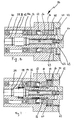
- Figure 1 shows a longitudinal section through a generally designated by the numeral 10 spindle device according to the invention.
- the spindle device 10 according to the invention is designed as a high-frequency spindle and is suitable for use for the highest speeds in numerous machine tools, in particular for milling or grinding machines.
- the spindle device 10 has a housing 12 in which a generally designated by the numeral 14 spindle is rotatably mounted.
- the spindle 14 has a first tool-side end 15 and a second end 17.
- a spindle shaft 16 is at the first end 15 by means of a bearing 22, and rotatably supported at the second end 17 by means of a second bearing 24.
- a tool clamping device 20 of basically known design is provided which can be actuated via a centrally arranged pull rod 18.
- the pull rod 18 is biased by a spring assembly 26 in a clamping position of the tool clamping device 20.
- a rotary feedthrough designated overall by the numeral 36 is installed in the housing 12 of the spindle 14.
- the rotary feedthrough 36 comprises an independent bearing 40 for a spindle section 39 with a central receptacle 38, in which the drawbar 18 is guided at its end remote from the tool clamping device 20.
- the rotary feedthrough 36 further has at its end remote from the tool clamping device 20 all connections for the supply and removal of coolant and optionally for other supply lines.
- the spindle device 10 has an external cooling for external cooling of the housing 12, wherein channels 32 and 34 for the supply and removal of coolant can be seen in FIG.
- the spindle device 10 is additionally provided with an internal cooling for the spindle 14, which has a plurality of closed cooling channels, through which coolant flows, which is supplied and / or removed via connections on the rotary leadthrough 36 in the axial direction.
- the spindle device 10 additionally has a possibility for a coolant supply via the rotary leadthrough 36 into a central axial channel 30 of the drawbar 18, so as to allow a coolant supply to the tool, if desired.
- the spindle device 10 according to the invention can also be configured without such an option, provided that no cooling of the tool via the spindle 14 is desired for the particular application.
- the motor 28 for driving the spindle shaft 16 has an integrated into the housing 12 stator 29, which is cooled via the cooling channels 32, 34 from the outside.
- the associated rotor 31 is located directly on the spindle shaft 16 and is cooled by the internal cooling of the spindle 14 from the inside.
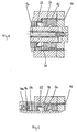
- the rotary feedthrough 36 is formed as a part with a separate housing 42 which is detachably connected to the housing 12 of the spindle device 10, for example screwed.
- a bearing with a bearing pair 40, 40a is installed, by means of which the spindle portion 39 is rotatably mounted with the central receptacle 38 for the pull rod 18.
- the rotary feedthrough 36 is closed by a flange 41 to the outside, through which all connecting lines for the spindle are guided to the outside and optionally provided with suitable screw connections.
- two inflow openings 44, 45 can be seen, which are coupled to coolant lines.
- the inflow openings 44, 45 are each provided with a flow channel 48 or 49, is supplied via the coolant for internal cooling of the spindle 14, wherein this is respectively deflected at the first end 15 of the spindle 14 and is discharged back via the flange 41 of the rotary feedthrough 36 into connected coolant lines.
- the two inflow openings 44, 45 open into a common cavity 43. It would thus be possible to dispense with one of the two inflow openings 44, 45 and the coolant supply only via an inflow opening (and correspondingly the coolant discharge only via a drain opening). It is understood that the inflow and outflow openings can also be reversed.
- the flow channels 48, 49 are now coupled to one another via a series of channel sections, which extend through the spindle section 39, the pull rod 18 and the spindle shaft 16.
- the flow channels open into a deflecting element 80 (FIG. 6) and are returned from the latter via return channels, which in turn extend via channel sections in the spindle shaft 16, in the pull rod 18 and the spindle section 39 of the rotary leadthrough 36 ,
- return channels which in turn extend via channel sections in the spindle shaft 16, in the pull rod 18 and the spindle section 39 of the rotary leadthrough 36 .
- the flow channels 48, 49 initially extend from the common cavity 43 through a channel section 96 of the spindle section 39, from the end of which a passage into a channel section 88 of the pull rod 18 takes place (see FIG 6).
- the coolant passes axially or radially at the end of the spindle portion 39 into a channel portion 96.
- the cavity 43 and the rotating spindle portion 39 are now sealed against the housing 42 of the rotary feedthrough 36 initially by a first gap seal 50. Since this gap seal 50 operates without contact, leakage losses are to be expected in this case. Therefore, the gap seal 50 is followed by a contact seal 52 in the form of a lip seal.
- the contact seal 52 can be acted upon by compressed air via a pressure channel 70 such that the sealing lip is lifted off the sealing surface during operation of the spindle 14 under the influence of the supplied compressed air.
- the contact seal 52 is non-contact during operation of the spindle 14 and thus subject to no wear even at high speeds. Leakage losses exiting via the first gap seal 50 are thus removed by the countercurrent compressed air into a leakage return 72, which is connected to a leakage discharge opening 74.
- the pressure channel 70 is sealed off from the bearing 40 via a second gap seal 54.
- the compressed air is throttled over the second gap seal 54, but this could possibly leak into the bearing 40 and thus affect its lubrication in an undesirable manner.
- the air exiting via the second gap seal 54 is discharged via a bore 76 into a relief channel 77 and from there reaches an outlet 78 or a hose connected thereto (see FIG.
- any deterioration of the lubrication of the bearing 40 adjacent to the contact seal 52 is prevented by the application of a pressure medium or compressed air.
- coolant in the central axial channel 30 of the drawbar 18 can be supplied.
- the central axial channel 30 opens on the tool side and thus allows a supply of coolant to the tool or workpiece.
- FIG. 6 shows how the coolant in the inlet direction 79 is led from the end of the channel section 96 into channel sections 88 of the drawbar 18, which open into pockets 86 formed between the drawbar 18 and the spindle shaft 16. From these pockets 86 from the coolant passes Radial depressions 89 in corresponding axial passage portions of the spindle shaft 16, via which the coolant is guided into the region of the bearing 22.
- a deflection of the coolant via a deflecting element 80 in associated return channels.
- the deflecting element 80 is formed as a cylindrical sleeve and has recesses in its lateral surface, into each of which opens a pair of flow channels and return channels.
- the deflecting element 80 is inserted into a bore 81 of the spindle shaft 16 such that a closed overflow space 82 is formed with the depressions and the inner wall of the bore 81, by which the connection between the flow and return passages is established.
- the coolant is returned from the front pockets 84 via axial channel sections 92 in the drawbar 18 and finally passes through further pockets 93 and radial bores 94 in the spindle section 39 of the rotary union 36 and is then discharged via the channel sections 95.
- From Figure 6 is also the supply of the coolant from the channel portions 96 of the spindle portion 39 via holes in the channel sections 88 of the tie rod 18 and of there from over radial channel sections into the pockets 86 recognizable.
- the channel sections of the flow or return channels can basically be designed as bores.
- an embodiment with a shrunk-in tube is conceivable, in which the channel sections are milled.
- the carrier of the rotor 99 can be used to form the channel sections.
- the cooling system of the spindle device 10 allows targeted internal cooling of the spindle 14 over its entire area, wherein all the bearings 22, 24, 40 and the area of the rotor 31 are cooled sufficiently, so that maintained an operating temperature of about 30 ° during operation can be.
- a supply of coolant via the central axial channel 30 of the pull rod 18 is possible in order to cool an inserted tool or a workpiece.
- an external cooling is provided, can be cooled by the motor or spindle from the outside.
Landscapes
- Engineering & Computer Science (AREA)
- Mechanical Engineering (AREA)
- Physics & Mathematics (AREA)
- Fluid Mechanics (AREA)
- Auxiliary Devices For Machine Tools (AREA)
Applications Claiming Priority (1)
| Application Number | Priority Date | Filing Date | Title |
|---|---|---|---|
| DE102005030277A DE102005030277B4 (de) | 2005-06-21 | 2005-06-21 | Spindelvorrichtung mit Innenkühlung |
Publications (3)
| Publication Number | Publication Date |
|---|---|
| EP1736277A2 true EP1736277A2 (fr) | 2006-12-27 |
| EP1736277A3 EP1736277A3 (fr) | 2007-04-04 |
| EP1736277B1 EP1736277B1 (fr) | 2008-07-02 |
Family
ID=36992779
Family Applications (1)
| Application Number | Title | Priority Date | Filing Date |
|---|---|---|---|
| EP06010514A Active EP1736277B1 (fr) | 2005-06-21 | 2006-05-22 | Broche avec passage interne de réfrigérant et circuit fermé de réfrigération passant à travers un joint rotatif |
Country Status (2)
| Country | Link |
|---|---|
| EP (1) | EP1736277B1 (fr) |
| DE (2) | DE102005030277B4 (fr) |
Cited By (18)
| Publication number | Priority date | Publication date | Assignee | Title |
|---|---|---|---|---|
| WO2007144405A1 (fr) | 2006-06-16 | 2007-12-21 | Mann+Hummel Gmbh | Élément de filtre compact avec protection de dépoussiérage |
| WO2008123407A1 (fr) * | 2007-03-30 | 2008-10-16 | Thk Co., Ltd. | Palier de rotation, dispositif de table de rotation et procédé de détermination d'un diamètre de table |
| EP2058085A1 (fr) * | 2007-11-08 | 2009-05-13 | Step-Tec AG | Refroidissement d'arbre pour une broche à moteur d'outil |
| ITMI20081999A1 (it) * | 2008-11-11 | 2010-05-12 | Capellini S R L | Dispositivo di sbloccaggio utensile con raffreddamento integrato, particolarmente per elettromandrini. |
| CN102902287A (zh) * | 2012-10-22 | 2013-01-30 | 北京工业大学 | 一种电主轴主动热平衡温控装置及温控方法 |
| CN104097100A (zh) * | 2013-04-08 | 2014-10-15 | 贝特霍尔德·赫姆勒机器制造股份公司 | 带有液体冷却部的两件式的工具主轴 |
| CN104174880A (zh) * | 2014-08-27 | 2014-12-03 | 江苏星晨高速电机有限公司 | 非接触式代替旋转接头用于卧式电主轴中空出水的装置 |
| CN104889425A (zh) * | 2015-06-11 | 2015-09-09 | 浙江日发精密机械股份有限公司 | 一种高速主轴箱结构 |
| CN109550978A (zh) * | 2019-02-15 | 2019-04-02 | 江苏凯勒姆智能装备有限公司 | 一种车铣加工设备的主轴箱 |
| CN109590750A (zh) * | 2019-02-15 | 2019-04-09 | 江苏凯勒姆智能装备有限公司 | 一种车铣复合加工设备 |
| EP3495677A1 (fr) | 2017-12-05 | 2019-06-12 | Fischer Engineering Solutions AG | Cartouche de palier à gaz et utilisation d'une cartouche de palier à gaz |
| CN110560715A (zh) * | 2019-09-27 | 2019-12-13 | 广州飞速尔精密部件有限公司 | 一种轴芯内冷却永磁同步雕铣电主轴 |
| CN110834102A (zh) * | 2019-11-23 | 2020-02-25 | 深圳市爱贝科精密机械有限公司 | 一种同步冷却型电主轴 |
| CN111940766A (zh) * | 2020-07-07 | 2020-11-17 | 广州市昊志机电股份有限公司 | 一种气浮电主轴和机床 |
| CN112895167A (zh) * | 2021-03-16 | 2021-06-04 | 施华平 | 用于水钻的冷却机构 |
| CN112974867A (zh) * | 2021-03-02 | 2021-06-18 | 广州市昊志机电股份有限公司 | 一种气浮电主轴和钻机 |
| CN113427400A (zh) * | 2021-07-08 | 2021-09-24 | 江苏工大金凯高端装备制造有限公司 | 一种高速气浮磨削主轴 |
| CN115498818A (zh) * | 2022-09-14 | 2022-12-20 | 无锡市荣华机械制造有限公司 | 一种恒转矩雕铣电动主轴 |
Families Citing this family (11)
| Publication number | Priority date | Publication date | Assignee | Title |
|---|---|---|---|---|
| DE102008026924B4 (de) * | 2008-06-05 | 2010-03-04 | Fischer AG Präzisionsspindeln | Drehdurchführung einer Kühlflüssigkeitszuführung |
| DE102008058941A1 (de) * | 2008-11-25 | 2010-05-27 | Franz Kessler Gmbh | Werkzeugmaschine |
| DE102010045285A1 (de) * | 2010-09-14 | 2012-03-15 | Josef Reinauer | Werkzeugmaschinenspindel mit automatischer Spannvorrichtung und integrierter pneumatischer Löseeinheit, zur lösbaren und axialfesten Fixierung von Werkzeugkomponenten |
| CN102120266A (zh) * | 2010-12-27 | 2011-07-13 | 东莞理工学院 | 高速精密电主轴冷却系统 |
| DE202012003528U1 (de) | 2012-04-05 | 2012-05-18 | Innovative Fertigungstechnologie Gmbh (Ift) | Einrichtung zur Kompensation thermischer Verformungen an einer Motorspindel |
| CN103737027A (zh) * | 2013-12-31 | 2014-04-23 | 广州市昊志机电股份有限公司 | 一种高速雕铣电主轴 |
| DE102016102035A1 (de) * | 2016-02-05 | 2017-08-10 | Röhm Gmbh | Werkzeugspindel |
| DE102016114036A1 (de) * | 2016-07-29 | 2018-02-01 | Ott-Jakob Spanntechnik Gmbh | Arbeitsspindel-Kühleinrichtung und Werkzeugmaschinen-Bearbeitungseinheit mit einer derartigen Arbeitspindel-Kühleinrichtung |
| DE102017121294B4 (de) * | 2017-09-14 | 2022-03-17 | Berg & Co. Gmbh | Spindeleinheit für Werkzeugmaschinen |
| DE102020120038B4 (de) | 2020-07-29 | 2024-10-31 | Technische Hochschule Köln | Verfahren zum Betreiben einer Temperiervorrichtung |
| EP4454807A3 (fr) * | 2024-09-13 | 2025-03-26 | Maschinenfabrik Berthold Hermle AG | Broche motorisée |
Family Cites Families (10)
| Publication number | Priority date | Publication date | Assignee | Title |
|---|---|---|---|---|
| DE3443537A1 (de) * | 1984-11-29 | 1986-06-05 | Werkzeugmaschinenfabrik Adolf Waldrich Coburg Gmbh & Co, 8630 Coburg | Lagerung einer werkzeugmaschinenspindel mit kuehleinrichtung in einem spindelstock |
| JP2677505B2 (ja) * | 1993-07-07 | 1997-11-17 | 株式会社牧野フライス製作所 | 工作機械の主軸装置 |
| DE19516986C2 (de) * | 1995-05-09 | 1999-01-07 | Sauter Kg Feinmechanik | Spindelkopf für Werkzeuge |
| JPH10230434A (ja) * | 1997-02-21 | 1998-09-02 | Gat G Fuer Antriebstechnik Mbh | 回転する機械部分に流体混合物を供給するための方法及び装置 |
| JP2000028870A (ja) * | 1998-07-14 | 2000-01-28 | Hitachi Ltd | 光結合装置 |
| JP2000158288A (ja) * | 1998-11-27 | 2000-06-13 | Koyo Mach Ind Co Ltd | 工作機械の主軸冷却装置およびスピンドル装置 |
| SE9901049L (sv) * | 1999-03-23 | 2000-02-28 | Lind Finance & Dev Ab | Anordning vid verktygsspindel |
| JP2000288870A (ja) * | 1999-04-08 | 2000-10-17 | Makino Milling Mach Co Ltd | 回転軸装置 |
| EP1143159B1 (fr) * | 1999-10-26 | 2004-05-19 | Makino Milling Machine Co. Ltd. | Dispositif a arbre rotatif et machine-outil comportant un tel dispositif a arbre rotatif |
| US6398468B1 (en) * | 2001-01-19 | 2002-06-04 | Bayer Machine Tech Llc | Machine tool quill spindle |
-
2005
- 2005-06-21 DE DE102005030277A patent/DE102005030277B4/de not_active Expired - Fee Related
-
2006
- 2006-05-22 DE DE502006001013T patent/DE502006001013D1/de active Active
- 2006-05-22 EP EP06010514A patent/EP1736277B1/fr active Active
Cited By (32)
| Publication number | Priority date | Publication date | Assignee | Title |
|---|---|---|---|---|
| WO2007144405A1 (fr) | 2006-06-16 | 2007-12-21 | Mann+Hummel Gmbh | Élément de filtre compact avec protection de dépoussiérage |
| WO2008123407A1 (fr) * | 2007-03-30 | 2008-10-16 | Thk Co., Ltd. | Palier de rotation, dispositif de table de rotation et procédé de détermination d'un diamètre de table |
| US8316776B2 (en) | 2007-03-30 | 2012-11-27 | Thk Co., Ltd. | Rotary bearing, rotary table device and table diameter determining method |
| CN101680488B (zh) * | 2007-03-30 | 2014-01-01 | Thk株式会社 | 旋转轴承、旋转工作台装置、工作台直径决定方法 |
| EP2058085A1 (fr) * | 2007-11-08 | 2009-05-13 | Step-Tec AG | Refroidissement d'arbre pour une broche à moteur d'outil |
| WO2009059954A1 (fr) * | 2007-11-08 | 2009-05-14 | Step-Tec Ag | Refroidissement d'arbre pour une broche motorisée d'un outil |
| CN101855043A (zh) * | 2007-11-08 | 2010-10-06 | 斯特普-特克股份公司 | 用于工具马达芯轴的轴冷却器 |
| US8684643B2 (en) | 2007-11-08 | 2014-04-01 | Step-Tec Ag | Shaft cooler for a tool motor spindle |
| CN101855043B (zh) * | 2007-11-08 | 2014-05-14 | 斯特普-特克股份公司 | 用于工具马达芯轴的轴冷却器 |
| ITMI20081999A1 (it) * | 2008-11-11 | 2010-05-12 | Capellini S R L | Dispositivo di sbloccaggio utensile con raffreddamento integrato, particolarmente per elettromandrini. |
| CN102902287B (zh) * | 2012-10-22 | 2015-08-05 | 北京工业大学 | 一种电主轴主动热平衡温控方法 |
| CN102902287A (zh) * | 2012-10-22 | 2013-01-30 | 北京工业大学 | 一种电主轴主动热平衡温控装置及温控方法 |
| CN104097100B (zh) * | 2013-04-08 | 2018-04-13 | 贝特霍尔德·赫姆勒机器制造股份公司 | 一种两件式的受力驱动的工具主轴 |
| EP2789423A1 (fr) * | 2013-04-08 | 2014-10-15 | Maschinenfabrik Berthold Hermle AG | Broche d'outil divisée en deux et dotée d'un refroidissement de liquide |
| CN104097100A (zh) * | 2013-04-08 | 2014-10-15 | 贝特霍尔德·赫姆勒机器制造股份公司 | 带有液体冷却部的两件式的工具主轴 |
| CN104174880A (zh) * | 2014-08-27 | 2014-12-03 | 江苏星晨高速电机有限公司 | 非接触式代替旋转接头用于卧式电主轴中空出水的装置 |
| CN104889425A (zh) * | 2015-06-11 | 2015-09-09 | 浙江日发精密机械股份有限公司 | 一种高速主轴箱结构 |
| EP3495677A1 (fr) | 2017-12-05 | 2019-06-12 | Fischer Engineering Solutions AG | Cartouche de palier à gaz et utilisation d'une cartouche de palier à gaz |
| CN109550978B (zh) * | 2019-02-15 | 2024-04-26 | 常州柯勒玛智能装备有限公司 | 一种车铣加工设备的主轴箱 |
| CN109550978A (zh) * | 2019-02-15 | 2019-04-02 | 江苏凯勒姆智能装备有限公司 | 一种车铣加工设备的主轴箱 |
| CN109590750A (zh) * | 2019-02-15 | 2019-04-09 | 江苏凯勒姆智能装备有限公司 | 一种车铣复合加工设备 |
| CN109590750B (zh) * | 2019-02-15 | 2024-05-31 | 常州柯勒玛智能装备有限公司 | 一种车铣复合加工设备 |
| CN110560715A (zh) * | 2019-09-27 | 2019-12-13 | 广州飞速尔精密部件有限公司 | 一种轴芯内冷却永磁同步雕铣电主轴 |
| CN110834102A (zh) * | 2019-11-23 | 2020-02-25 | 深圳市爱贝科精密机械有限公司 | 一种同步冷却型电主轴 |
| CN111940766B (zh) * | 2020-07-07 | 2022-09-02 | 广州市昊志机电股份有限公司 | 一种气浮电主轴和机床 |
| CN111940766A (zh) * | 2020-07-07 | 2020-11-17 | 广州市昊志机电股份有限公司 | 一种气浮电主轴和机床 |
| CN112974867A (zh) * | 2021-03-02 | 2021-06-18 | 广州市昊志机电股份有限公司 | 一种气浮电主轴和钻机 |
| CN112895167A (zh) * | 2021-03-16 | 2021-06-04 | 施华平 | 用于水钻的冷却机构 |
| CN113427400A (zh) * | 2021-07-08 | 2021-09-24 | 江苏工大金凯高端装备制造有限公司 | 一种高速气浮磨削主轴 |
| CN113427400B (zh) * | 2021-07-08 | 2023-08-15 | 江苏工大金凯高端装备制造有限公司 | 一种高速气浮磨削主轴 |
| CN115498818A (zh) * | 2022-09-14 | 2022-12-20 | 无锡市荣华机械制造有限公司 | 一种恒转矩雕铣电动主轴 |
| CN115498818B (zh) * | 2022-09-14 | 2024-02-20 | 无锡市荣华机械制造有限公司 | 一种恒转矩雕铣电动主轴 |
Also Published As
| Publication number | Publication date |
|---|---|
| DE102005030277A1 (de) | 2007-01-04 |
| EP1736277B1 (fr) | 2008-07-02 |
| DE102005030277B4 (de) | 2007-10-31 |
| DE502006001013D1 (de) | 2008-08-14 |
| EP1736277A3 (fr) | 2007-04-04 |
Similar Documents
| Publication | Publication Date | Title |
|---|---|---|
| EP1736277B1 (fr) | Broche avec passage interne de réfrigérant et circuit fermé de réfrigération passant à travers un joint rotatif | |
| EP2058085B1 (fr) | Refroidissement d'arbre pour une broche à moteur d'outil | |
| DE102010037822B4 (de) | Werkzeugaufnahme zum Einsatz in einer Werkzeugmaschine und Verfahren zum Betreiben einer solchen Werkzeugaufnahme | |
| DE3443537C2 (fr) | ||
| WO2012098224A1 (fr) | Tourelle porte-outils pour l'usinage de pièces et système d'usinage équipé d'une telle tourelle porte-outils | |
| WO1997045667A1 (fr) | Passage tournant pour hautes pressions et vitesses relatives elevees | |
| DE102004018154B4 (de) | Zylinderrollenlager und Käfig für Zylinderrollenlager | |
| EP0865837B1 (fr) | Entraínement pour laminoir comprenant des broches articulées à joint denté et un dispositif de graissage par circulation | |
| DE10027750C5 (de) | Motorspindel für eine Werkzeugmaschine sowie Moduleinheit für eine solche | |
| EP0440096B1 (fr) | Arrangement pour broches pour pièces de travail pour un tour | |
| DE202009009424U1 (de) | Werkzeugmaschine mit luftgekühlter Spindelwelle | |
| DE60013569T2 (de) | Vorrichtung für eine werkzeugspindel | |
| EP2433741B1 (fr) | Machine-outil dotée d'une unité de broche échangeable | |
| EP1666671B1 (fr) | Fraise pour paroi moulée | |
| DE102008064410A1 (de) | Bearbeitungsmaschine | |
| DE102019007416A1 (de) | Spindelvorrichtung | |
| DE60013572T2 (de) | Vorrichtung für eine werkzeugspindel | |
| EP2193907A1 (fr) | Machine à vis avec compensation axiale de la expansion thermique | |
| DE2911000C2 (de) | Drehdurchführung für die Einleitung strömungsfähiger Medien in ein rotierendes Maschinenteil | |
| DE10135419A1 (de) | Werkzeugkopf für eine Werkzeugmaschine | |
| DE60013571T2 (de) | Vorrichtung für eine werkzeugspindel | |
| DE102021126074B4 (de) | Elektrische Maschine mit Rotorkühlung | |
| DE60013568T2 (de) | Vorrichtung für eine werkzeugspindel | |
| EP1245329A1 (fr) | Dispositif pour l'alimentation en fluide de refroidissement et de lubrification d'un outil avec courant interne pour ce fluide | |
| DE60013570T2 (de) | Vorrichtung für eine werkzeugspindel |
Legal Events
| Date | Code | Title | Description |
|---|---|---|---|
| PUAI | Public reference made under article 153(3) epc to a published international application that has entered the european phase |
Free format text: ORIGINAL CODE: 0009012 |
|
| AK | Designated contracting states |
Kind code of ref document: A2 Designated state(s): AT BE BG CH CY CZ DE DK EE ES FI FR GB GR HU IE IS IT LI LT LU LV MC NL PL PT RO SE SI SK TR |
|
| AX | Request for extension of the european patent |
Extension state: AL BA HR MK YU |
|
| PUAL | Search report despatched |
Free format text: ORIGINAL CODE: 0009013 |
|
| AK | Designated contracting states |
Kind code of ref document: A3 Designated state(s): AT BE BG CH CY CZ DE DK EE ES FI FR GB GR HU IE IS IT LI LT LU LV MC NL PL PT RO SE SI SK TR |
|
| AX | Request for extension of the european patent |
Extension state: AL BA HR MK YU |
|
| 17P | Request for examination filed |
Effective date: 20070530 |
|
| AKX | Designation fees paid |
Designated state(s): CH DE IT LI |
|
| GRAP | Despatch of communication of intention to grant a patent |
Free format text: ORIGINAL CODE: EPIDOSNIGR1 |
|
| GRAS | Grant fee paid |
Free format text: ORIGINAL CODE: EPIDOSNIGR3 |
|
| GRAA | (expected) grant |
Free format text: ORIGINAL CODE: 0009210 |
|
| AK | Designated contracting states |
Kind code of ref document: B1 Designated state(s): CH DE IT LI |
|
| REG | Reference to a national code |
Ref country code: CH Ref legal event code: EP |
|
| REF | Corresponds to: |
Ref document number: 502006001013 Country of ref document: DE Date of ref document: 20080814 Kind code of ref document: P |
|
| REG | Reference to a national code |
Ref country code: CH Ref legal event code: NV Representative=s name: BRAUNPAT BRAUN EDER AG |
|
| PLBE | No opposition filed within time limit |
Free format text: ORIGINAL CODE: 0009261 |
|
| STAA | Information on the status of an ep patent application or granted ep patent |
Free format text: STATUS: NO OPPOSITION FILED WITHIN TIME LIMIT |
|
| 26N | No opposition filed |
Effective date: 20090403 |
|
| REG | Reference to a national code |
Ref country code: CH Ref legal event code: NV Representative=s name: HEPP WENGER RYFFEL AG |
|
| REG | Reference to a national code |
Ref country code: DE Ref legal event code: R082 Ref document number: 502006001013 Country of ref document: DE Representative=s name: GLAWE DELFS MOLL PARTNERSCHAFT MBB VON PATENT-, DE Ref country code: DE Ref legal event code: R082 Ref document number: 502006001013 Country of ref document: DE |
|
| REG | Reference to a national code |
Ref country code: DE Ref legal event code: R082 Ref document number: 502006001013 Country of ref document: DE Ref country code: DE Ref legal event code: R082 Ref document number: 502006001013 Country of ref document: DE Representative=s name: GLAWE DELFS MOLL PARTNERSCHAFT MBB VON PATENT-, DE |
|
| REG | Reference to a national code |
Ref country code: DE Ref legal event code: R082 Ref document number: 502006001013 Country of ref document: DE Representative=s name: GLAWE DELFS MOLL PARTNERSCHAFT MBB VON PATENT-, DE |
|
| REG | Reference to a national code |
Ref country code: DE Ref legal event code: R082 Ref document number: 502006001013 Country of ref document: DE Representative=s name: WITTE, WELLER & PARTNER PATENTANWAELTE MBB, DE |
|
| PGFP | Annual fee paid to national office [announced via postgrant information from national office to epo] |
Ref country code: DE Payment date: 20250429 Year of fee payment: 20 |
|
| PGFP | Annual fee paid to national office [announced via postgrant information from national office to epo] |
Ref country code: IT Payment date: 20250522 Year of fee payment: 20 |
|
| PGFP | Annual fee paid to national office [announced via postgrant information from national office to epo] |
Ref country code: CH Payment date: 20250601 Year of fee payment: 20 |