EP1736332A2 - Dispositif pour le guidage cinématique d'une roue directrice de véhicule pour essieu avant rigide d'un véhicule utilitaire - Google Patents
Dispositif pour le guidage cinématique d'une roue directrice de véhicule pour essieu avant rigide d'un véhicule utilitaire Download PDFInfo
- Publication number
- EP1736332A2 EP1736332A2 EP06012205A EP06012205A EP1736332A2 EP 1736332 A2 EP1736332 A2 EP 1736332A2 EP 06012205 A EP06012205 A EP 06012205A EP 06012205 A EP06012205 A EP 06012205A EP 1736332 A2 EP1736332 A2 EP 1736332A2
- Authority
- EP
- European Patent Office
- Prior art keywords
- wheel
- vehicle
- steering
- offset
- axle
- Prior art date
- Legal status (The legal status is an assumption and is not a legal conclusion. Google has not performed a legal analysis and makes no representation as to the accuracy of the status listed.)
- Granted
Links
Images

Classifications
-
- B—PERFORMING OPERATIONS; TRANSPORTING
- B60—VEHICLES IN GENERAL
- B60G—VEHICLE SUSPENSION ARRANGEMENTS
- B60G9/00—Resilient suspensions of a rigid axle or axle housing for two or more wheels
- B60G9/003—Resilient suspensions of a rigid axle or axle housing for two or more wheels the axle being rigidly connected to a trailing guiding device
-
- B—PERFORMING OPERATIONS; TRANSPORTING
- B60—VEHICLES IN GENERAL
- B60G—VEHICLE SUSPENSION ARRANGEMENTS
- B60G2200/00—Indexing codes relating to suspension types
- B60G2200/40—Indexing codes relating to the wheels in the suspensions
- B60G2200/44—Indexing codes relating to the wheels in the suspensions steerable
-
- B—PERFORMING OPERATIONS; TRANSPORTING
- B60—VEHICLES IN GENERAL
- B60G—VEHICLE SUSPENSION ARRANGEMENTS
- B60G2200/00—Indexing codes relating to suspension types
- B60G2200/40—Indexing codes relating to the wheels in the suspensions
- B60G2200/46—Indexing codes relating to the wheels in the suspensions camber angle
-
- B—PERFORMING OPERATIONS; TRANSPORTING
- B60—VEHICLES IN GENERAL
- B60G—VEHICLE SUSPENSION ARRANGEMENTS
- B60G2200/00—Indexing codes relating to suspension types
- B60G2200/40—Indexing codes relating to the wheels in the suspensions
- B60G2200/464—Caster angle
-
- B—PERFORMING OPERATIONS; TRANSPORTING
- B60—VEHICLES IN GENERAL
- B60G—VEHICLE SUSPENSION ARRANGEMENTS
- B60G2206/00—Indexing codes related to the manufacturing of suspensions: constructional features, the materials used, procedures or tools
- B60G2206/01—Constructional features of suspension elements, e.g. arms, dampers, springs
- B60G2206/30—Constructional features of rigid axles
-
- B—PERFORMING OPERATIONS; TRANSPORTING
- B60—VEHICLES IN GENERAL
- B60G—VEHICLE SUSPENSION ARRANGEMENTS
- B60G2206/00—Indexing codes related to the manufacturing of suspensions: constructional features, the materials used, procedures or tools
- B60G2206/01—Constructional features of suspension elements, e.g. arms, dampers, springs
- B60G2206/50—Constructional features of wheel supports or knuckles, e.g. steering knuckles, spindle attachments
Definitions
- the invention relates to a device for kinematic guidance of a steered vehicle wheel on a rigid front axle of a heavy commercial vehicle with a wheel, to which the wheel is to be rotatably supported, and a Radan gleichstelle on which the wheel carrier to a caster angle having a steering axis pivotally connected to a Vehicle body connected rigid axle body is mounted.
- Out DE 198 09 209 A1 is a rigid front axle known for a heavy commercial vehicle.
- the rigid axle of the known front axle forms with a right and a left trailing arm a self-stabilizing Achsverbund, the trailing arms are connected at their front ends on the vehicle frame and at their rear ends on the rigid axle.
- the transverse guidance of the axle is realized by a Panhard rod, which is connected to the frame side at one end and the other end at the other end.
- the trailing distance is generated in a conventional manner by a caster angle, which has the steering axle of the suspension.
- a positive caster angle causes a camber change when turning the wheels for cornering.
- a negative camber on the outside wheel and a positive camber on the inside of the wheel give good cornering during cornering.
- the steering axis, ie the Achsschenkelfitachse of the wheel carrier can be spatially oriented so that the caster angle is as tangential to the Raderhebungskveve so that reactions of the axle to be influenced favorable impact excitations of the road. Due to the trailing distance is further in conjunction with resulting from the lateral force moments the cornering provided for an automatic return of the steering.
- the increase in the caster angle is limited, since too great a resulting follow-up distance generated together with the lateral forces restoring moments, which require considerable holding forces on the steering especially at high lateral acceleration.
- the object of the invention is therefore to provide a device of the type mentioned, in which the limits within which the kinematic parameters can be selected without adverse effects on the wheel, be extended.
- the caster offset is in the side view of the vehicle, the horizontal distance between the steering axle and the spreading axis of the wheel center. Due to the tracking offset, one reaches an extension of the limits within which the caster angle and the resulting caster distance can be selected.
- the overtravel offset is positive if the overtravel distance is increased at a constant caster angle and is negative if the caster distance is reduced at the same caster angle.
- With a positive trailing offset of the wheel center, seen in the forward direction, behind the steering axis or Spreizachse and negative caster offset is the wheel center, seen in the forward direction, in front of the steering axle or Spreizachse. For a given trailing distance, a large trailing angle can be made possible by a negative trailing offset.
- both a positive and a negative tracking offset can be used, wherein preferably a negative tracking offset is used.
- the tracking offset is realized on the wheel carrier, in particular steering knuckle.
- it is a steering knuckle, which two bearing openings and a wheel bearing pin.
- a king pin fastened to the rigid axle body is inserted in a known manner through the bearing openings on the steering knuckle.
- the bearing openings are arranged on the steering knuckle such that the center line common to the two bearing openings, which defines the steering axis or spreading axis, is offset relative to the axis of rotation formed by the wheel bearing pin for the wheel.
- the trailing offset and the spatial arrangement of the steering axle or Spreizachse are provided so that when cornering the inside wheel run a positive camber change and the outside wheel a negative camber change.
- the wheel brake in particular brake caliper, according to the installation space conditions, also be arranged in front of or above the wheel center.
- the steering axis of the wheel carrier can be as tangential as possible to the Raderhebungskurve.
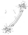
- the rigid front axle 1 has a Starrachsêt 5, which, for example, in a rigid front axle of a heavy commercial vehicle, as shown DE 198 09 209 A1 is known, is installed.
- Starrachspian 5 which, for example, in a rigid front axle of a heavy commercial vehicle, as shown DE 198 09 209 A1 is known, is installed.
- wheel suspensions are provided at both ends of the rigid axle body 5 in wheel carrier connecting points 3, which wheel carriers 2 have in the form of stub axles.
- Each wheel carrier 2 has a wheel bearing pin 9, on which the vehicle wheel 13 is rotatably mounted about a rotation axis 10.
- the respective wheel carrier 2 is pivotally mounted about a steering axis 4 at the Radan gleichstelle 3.
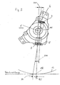
- the steering axle or spreading axis 4 is a kingpin 14 ( Figure 4) determines which is firmly connected in the respective Radyan gleichstelle 3 with the rigid axle 5.
- the kingpin 14 protrudes through bearing holes 7, 8 on the wheel 2.
- the steering axle 4 has a caster angle NW ( Figures 2, 3).
- the caster angle NW is in side view of the vehicle, the inclination of the steering axis 4 with respect to a vertical reference line. Due to the caster angle NW a trailing path NS is formed.
- the caster line is in side view of the vehicle, the distance between a puncture point 11 of the steering axle 4 through the footprint on which the vehicle wheel 13 stands up, and a Radaufstandstician 12, which forms approximately the center of the Laces, in which the vehicle tire contacts the footprint.
- the wheel contact point 12 is, as can be seen from Figure 4, in a Radstoffebene which intersects the axis of rotation 10 of the wheel in a Radstoffddling 6.
- the wheel contact point 12 is perpendicular below the wheel center. 6
- the steering axle 4 has a caster offset NV relative to the wheel center 6 or relative to the axis of rotation 10.
- a negative tracking offset by which, as can be seen from Figure 2, a reduction of the trailing path NS can be achieved.
- the tracking offset can also be formed positively, as shown schematically in Figure 3. This achieves an increase in the trailing distance NS.
- the reduction (negative tracking offset) and the increase in the tracking distance (positive tracking offset) can be achieved without changing the caster angle NW.
- the caster angle NW can be selected by utilizing the caster offset within a relatively large angle range. Due to the tracking offset, there are extended possibilities for optimizing the driving behavior, since the kinematic parameters can be selected within enlarged ranges.
- the steering shaft 4 further has, as can be seen from Figure 4, a spread angle SW.
- the spread angle SW referred to in vehicle front view or in the cross section of the vehicle, the inclination (spread) of the steering axis 4 (Spreizachse).
- the spread angle SW like the caster angle NW, determined by the kingpin 14, which is inserted into the two bearing openings 7, 8 of the steering knuckle or wheel carrier 2.
- the spread angle indicates the inclination of the steering axle 4 formed thereby with respect to a vertical reference line passing through the puncture point 11 of the steering shaft 4 through the wheel contact surface.
- a Lenkrollradius LRR which is in the cross section of the vehicle, the distance between the puncture point 11 and the Radaufstandstician 12.
- Another kinematic parameter is a spreading offset SV, which is the horizontal distance of the wheel center 6 from a fist point 15 in the cross section of the vehicle.
- the fist point 15 is the intersection of a horizontal plane, through the wheel center 6 with the steering axis 4.
- the axis of rotation 10 of the wheel 13 is in this horizontal plane. If the vehicle wheel 13 has a fall, the axis of rotation 10 of the wheel 13 is outside the horizontal plane passing through the wheel center 6 level.
- the wheel center point 6 and the axis of rotation 10 of the wheel 13 lie behind the steering axis 4 (FIG. 3) and the track axis 10 of the wheel 13 and the wheel center point 6 are located in front of the steering axis 4 (FIG. 3) with a negative trailing offset NV (FIG. Figure 2).
- NV negative trailing offset
- the fist point 15 seen in the forward direction of travel, lies in front of the axis of rotation 10 of the wheel 13 and with a negative trailing offset NV (FIG. 2), the fist point 15 lies behind the axis of rotation 10 of the wheel 13.
- the trailing offset NV is realized by the offset of the radial pin 9 relative to the common, the steering axis 4 defining center line of the bearing openings 7, 8 and inserted into the bearing openings 7, 8 kingpin 14. Due to the enlargement of the lug track both the spreading offset SV and the steering roller radius LRR be reduced. As far as an increase in the spread causes a positive camber both inside and outside the curve when cornering at the wheels, this can be counteracted by increasing the caster angle, as explained above.
Landscapes
- Engineering & Computer Science (AREA)
- Mechanical Engineering (AREA)
- Vehicle Body Suspensions (AREA)
Applications Claiming Priority (1)
| Application Number | Priority Date | Filing Date | Title |
|---|---|---|---|
| DE200510028852 DE102005028852A1 (de) | 2005-06-22 | 2005-06-22 | Vorrichtung zur kinematischen Führung eines gelenkten Fahrzeugrades an einer starren Vorderachse eines Nutzfahrzeugs |
Publications (3)
| Publication Number | Publication Date |
|---|---|
| EP1736332A2 true EP1736332A2 (fr) | 2006-12-27 |
| EP1736332A3 EP1736332A3 (fr) | 2007-11-28 |
| EP1736332B1 EP1736332B1 (fr) | 2012-02-01 |
Family
ID=36933343
Family Applications (1)
| Application Number | Title | Priority Date | Filing Date |
|---|---|---|---|
| EP20060012205 Not-in-force EP1736332B1 (fr) | 2005-06-22 | 2006-06-14 | Dispositif pour le guidage cinématique d'une roue directrice de véhicule pour essieu avant rigide d'un véhicule utilitaire |
Country Status (2)
| Country | Link |
|---|---|
| EP (1) | EP1736332B1 (fr) |
| DE (1) | DE102005028852A1 (fr) |
Cited By (2)
| Publication number | Priority date | Publication date | Assignee | Title |
|---|---|---|---|---|
| CN107773357A (zh) * | 2017-11-10 | 2018-03-09 | 左国刚 | 智能轮椅 |
| CN113752750A (zh) * | 2021-10-14 | 2021-12-07 | 郑州精通汽车零部件有限公司 | 一种客车用随动转向结构 |
Citations (1)
| Publication number | Priority date | Publication date | Assignee | Title |
|---|---|---|---|---|
| DE19809209A1 (de) | 1998-03-04 | 1999-09-09 | Man Nutzfahrzeuge Ag | Fahrgestell eines Frontlenker-Lastkraftwagen |
Family Cites Families (5)
| Publication number | Priority date | Publication date | Assignee | Title |
|---|---|---|---|---|
| DE9320479U1 (de) * | 1993-06-25 | 1994-08-25 | Claas Saulgau Gmbh, 88348 Saulgau | Frei schwenkbare Nachlaufräder für landwirtschaftliche Arbeitsmaschinen, insbesondere Kreiselheumaschinen |
| DE19717069C2 (de) * | 1997-04-23 | 1999-09-23 | Daimler Chrysler Ag | Einzelradaufhängung für gelenkte Räder von Kraftfahrzeugen, insbesondere Personenkraftwagen |
| DE19840135A1 (de) * | 1998-09-03 | 2000-03-09 | Volkswagen Ag | Aufhängung einer Starrachse für ein Kraftfahrzeug |
| DE19919845A1 (de) * | 1999-04-30 | 2000-11-09 | Trepte Gmbh Metall Und Fahrzeu | Radaufhängung, insbesondere für lenkbare Vorderräder |
| DE10247699B4 (de) * | 2002-10-12 | 2007-08-09 | Deere & Company, Moline | Lenkeinrichtung einer landwirtschaftlichen Erntemaschine |
-
2005
- 2005-06-22 DE DE200510028852 patent/DE102005028852A1/de not_active Withdrawn
-
2006
- 2006-06-14 EP EP20060012205 patent/EP1736332B1/fr not_active Not-in-force
Patent Citations (1)
| Publication number | Priority date | Publication date | Assignee | Title |
|---|---|---|---|---|
| DE19809209A1 (de) | 1998-03-04 | 1999-09-09 | Man Nutzfahrzeuge Ag | Fahrgestell eines Frontlenker-Lastkraftwagen |
Cited By (2)
| Publication number | Priority date | Publication date | Assignee | Title |
|---|---|---|---|---|
| CN107773357A (zh) * | 2017-11-10 | 2018-03-09 | 左国刚 | 智能轮椅 |
| CN113752750A (zh) * | 2021-10-14 | 2021-12-07 | 郑州精通汽车零部件有限公司 | 一种客车用随动转向结构 |
Also Published As
| Publication number | Publication date |
|---|---|
| DE102005028852A1 (de) | 2007-01-04 |
| EP1736332B1 (fr) | 2012-02-01 |
| EP1736332A3 (fr) | 2007-11-28 |
Similar Documents
| Publication | Publication Date | Title |
|---|---|---|
| WO2007118629A1 (fr) | FUSéE D'ESSIEU POUR VéHICULE | |
| EP3452310B1 (fr) | Suspension à roues indépendantes d'un véhicule, dotée d'un élément formant ressort à lame guidant les roues, réalisé dans un matériau composite fibreux | |
| DE3514788A1 (de) | Radaufhaengung | |
| EP0141093A2 (fr) | Suspension pour des roues avant dirigeables de véhicules automobiles | |
| DE202012004661U1 (de) | Anhänger für ein Lastwagengespann | |
| DE102015001864A1 (de) | Radaufhängung für einen Mobilkran sowie Mobilkran | |
| EP2207690A1 (fr) | Suspension à roues indépendantes | |
| DE102007047791A1 (de) | Einzelradaufhängung | |
| EP0873891A2 (fr) | Suspension indépendante pour roues directrices de véhicules à moteur, en particlierr de voitures automobiles | |
| DE60315541T2 (de) | Befestigungsaufbau für einen Radträger eines Kraftfahrzeugs | |
| DE2745970A1 (de) | Radaufhaengung fuer fahrzeuge | |
| EP2874831B1 (fr) | Suspension de roue pour le pont arrière d'un véhicule | |
| WO2024074520A1 (fr) | Système de suspension de roue de véhicule à moteur, et véhicule à moteur | |
| DE102009059029A1 (de) | Einzelradaufhängung eines insbesondere nicht lenkbaren Rades eines zweispurigen Fahrzeugs | |
| DE3912520B4 (de) | Hinterachse für ein Kraftfahrzeug | |
| EP1736332B1 (fr) | Dispositif pour le guidage cinématique d'une roue directrice de véhicule pour essieu avant rigide d'un véhicule utilitaire | |
| DE602004011866T2 (de) | Radaufhängung | |
| DE60011899T2 (de) | Fahrzeugaufhängungssystem | |
| DE3315505C2 (de) | Radaufhängung für Hinterräder von Kraftfahrzeugen | |
| DE102023109407A1 (de) | Aufhängungssystem für ein Kraftfahrzeug | |
| DE10329689A1 (de) | Achsaufhängung für Kraftfahrzeuge | |
| DE3833954C2 (fr) | ||
| DE3015586A1 (de) | Vorderradaufhaengung fuer kraftfahrzeuge | |
| DE102007047792A1 (de) | Einzelradaufhängung | |
| DE19840135A1 (de) | Aufhängung einer Starrachse für ein Kraftfahrzeug |
Legal Events
| Date | Code | Title | Description |
|---|---|---|---|
| PUAI | Public reference made under article 153(3) epc to a published international application that has entered the european phase |
Free format text: ORIGINAL CODE: 0009012 |
|
| AK | Designated contracting states |
Kind code of ref document: A2 Designated state(s): AT BE BG CH CY CZ DE DK EE ES FI FR GB GR HU IE IS IT LI LT LU LV MC NL PL PT RO SE SI SK TR |
|
| AX | Request for extension of the european patent |
Extension state: AL BA HR MK YU |
|
| PUAL | Search report despatched |
Free format text: ORIGINAL CODE: 0009013 |
|
| AK | Designated contracting states |
Kind code of ref document: A3 Designated state(s): AT BE BG CH CY CZ DE DK EE ES FI FR GB GR HU IE IS IT LI LT LU LV MC NL PL PT RO SE SI SK TR |
|
| AX | Request for extension of the european patent |
Extension state: AL BA HR MK YU |
|
| 17P | Request for examination filed |
Effective date: 20071208 |
|
| AKX | Designation fees paid |
Designated state(s): DE FR IT NL SE |
|
| RAP1 | Party data changed (applicant data changed or rights of an application transferred) |
Owner name: MAN TRUCK & BUS AG |
|
| GRAP | Despatch of communication of intention to grant a patent |
Free format text: ORIGINAL CODE: EPIDOSNIGR1 |
|
| RIN1 | Information on inventor provided before grant (corrected) |
Inventor name: SCHMITT, PETER, DIPL.ING. (FH) Inventor name: NICKELS, THOMAS, DIPL.-ING. Inventor name: TEUBNER, DANIEL, DIPL.-ING. Inventor name: ROSSOL, MARTIN, DIPL.-ING. (FH) |
|
| GRAS | Grant fee paid |
Free format text: ORIGINAL CODE: EPIDOSNIGR3 |
|
| GRAA | (expected) grant |
Free format text: ORIGINAL CODE: 0009210 |
|
| AK | Designated contracting states |
Kind code of ref document: B1 Designated state(s): DE FR IT NL SE |
|
| REG | Reference to a national code |
Ref country code: DE Ref legal event code: R096 Ref document number: 502006010935 Country of ref document: DE Effective date: 20120322 |
|
| REG | Reference to a national code |
Ref country code: SE Ref legal event code: TRGR |
|
| REG | Reference to a national code |
Ref country code: NL Ref legal event code: T3 |
|
| PLBE | No opposition filed within time limit |
Free format text: ORIGINAL CODE: 0009261 |
|
| STAA | Information on the status of an ep patent application or granted ep patent |
Free format text: STATUS: NO OPPOSITION FILED WITHIN TIME LIMIT |
|
| 26N | No opposition filed |
Effective date: 20121105 |
|
| REG | Reference to a national code |
Ref country code: DE Ref legal event code: R097 Ref document number: 502006010935 Country of ref document: DE Effective date: 20121105 |
|
| REG | Reference to a national code |
Ref country code: FR Ref legal event code: PLFP Year of fee payment: 11 |
|
| REG | Reference to a national code |
Ref country code: FR Ref legal event code: PLFP Year of fee payment: 12 |
|
| REG | Reference to a national code |
Ref country code: FR Ref legal event code: PLFP Year of fee payment: 13 |
|
| REG | Reference to a national code |
Ref country code: DE Ref legal event code: R081 Ref document number: 502006010935 Country of ref document: DE Owner name: MAN TRUCK & BUS SE, DE Free format text: FORMER OWNER: MAN TRUCK & BUS AG, 80995 MUENCHEN, DE |
|
| PGFP | Annual fee paid to national office [announced via postgrant information from national office to epo] |
Ref country code: SE Payment date: 20230317 Year of fee payment: 18 |
|
| PGFP | Annual fee paid to national office [announced via postgrant information from national office to epo] |
Ref country code: NL Payment date: 20230626 Year of fee payment: 18 Ref country code: FR Payment date: 20230622 Year of fee payment: 18 Ref country code: DE Payment date: 20230627 Year of fee payment: 18 |
|
| PGFP | Annual fee paid to national office [announced via postgrant information from national office to epo] |
Ref country code: IT Payment date: 20230620 Year of fee payment: 18 |
|
| REG | Reference to a national code |
Ref country code: DE Ref legal event code: R119 Ref document number: 502006010935 Country of ref document: DE |
|
| REG | Reference to a national code |
Ref country code: SE Ref legal event code: EUG |
|
| REG | Reference to a national code |
Ref country code: NL Ref legal event code: MM Effective date: 20240701 |
|
| PG25 | Lapsed in a contracting state [announced via postgrant information from national office to epo] |
Ref country code: NL Free format text: LAPSE BECAUSE OF NON-PAYMENT OF DUE FEES Effective date: 20240701 |
|
| PG25 | Lapsed in a contracting state [announced via postgrant information from national office to epo] |
Ref country code: NL Free format text: LAPSE BECAUSE OF NON-PAYMENT OF DUE FEES Effective date: 20240701 |
|
| PG25 | Lapsed in a contracting state [announced via postgrant information from national office to epo] |
Ref country code: DE Free format text: LAPSE BECAUSE OF NON-PAYMENT OF DUE FEES Effective date: 20250101 |
|
| PG25 | Lapsed in a contracting state [announced via postgrant information from national office to epo] |
Ref country code: FR Free format text: LAPSE BECAUSE OF NON-PAYMENT OF DUE FEES Effective date: 20240630 |
|
| PG25 | Lapsed in a contracting state [announced via postgrant information from national office to epo] |
Ref country code: IT Free format text: LAPSE BECAUSE OF NON-PAYMENT OF DUE FEES Effective date: 20240614 |
|
| PG25 | Lapsed in a contracting state [announced via postgrant information from national office to epo] |
Ref country code: SE Free format text: LAPSE BECAUSE OF NON-PAYMENT OF DUE FEES Effective date: 20240615 |