EP1736341A2 - Cabriolet-Fahrzeug mit einem in einem Verdeckablageraum ablegbaren Verdeck - Google Patents
Cabriolet-Fahrzeug mit einem in einem Verdeckablageraum ablegbaren Verdeck Download PDFInfo
- Publication number
- EP1736341A2 EP1736341A2 EP06012913A EP06012913A EP1736341A2 EP 1736341 A2 EP1736341 A2 EP 1736341A2 EP 06012913 A EP06012913 A EP 06012913A EP 06012913 A EP06012913 A EP 06012913A EP 1736341 A2 EP1736341 A2 EP 1736341A2
- Authority
- EP
- European Patent Office
- Prior art keywords
- pivoting
- convertible
- flap
- vehicle
- vehicle according
- Prior art date
- Legal status (The legal status is an assumption and is not a legal conclusion. Google has not performed a legal analysis and makes no representation as to the accuracy of the status listed.)
- Granted
Links
Images


Classifications
-
- B—PERFORMING OPERATIONS; TRANSPORTING
- B60—VEHICLES IN GENERAL
- B60J—WINDOWS, WINDSCREENS, NON-FIXED ROOFS, DOORS, OR SIMILAR DEVICES FOR VEHICLES; REMOVABLE EXTERNAL PROTECTIVE COVERINGS SPECIALLY ADAPTED FOR VEHICLES
- B60J7/00—Non-fixed roofs; Roofs with movable panels, e.g. rotary sunroofs
- B60J7/20—Vehicle storage compartments for roof parts or for collapsible flexible tops
- B60J7/207—Vehicle storage compartments for roof parts or for collapsible flexible tops being adjustable in volume, i.e. collapsible in order to increase luggage space in boot when roof is not stored
Definitions
- the invention relates to a convertible vehicle with a can be stored in a top storage compartment.
- a convertible vehicle with a can be stored in a top storage compartment.
- the pivoting of the pivoting part and the flap part are carried out independently manually, wherein additional, manually releasable locking means are provided for locking said components in at least one of the end positions, which are manually unlocked.
- the invention has for its object to further develop a generic convertible vehicle to the effect that the opening and closing of the top is easy.
- a drive device is provided, so that both the pivoting part and the flap part in a simple manner, preferably automated, are pivotable, so that the adjustment of the separating device between the convertible top position, in which the delimited by the separator from the luggage compartment top storage space is maximum, and the Baggage taking position, in which the top storage space has virtually no volume and the luggage compartment is maximum, without cumbersome manipulation is possible.
- a single drive device for example an electrical actuator, is provided for pivoting both the pivoting part and the flap part.
- a convertible vehicle has a vehicle structure with a partition wall 16 which ends at the top in a cross member 10 and the rear compartment 12 of the passenger compartment 14, in which a through-opening 18 is formed, through which bulky, in the luggage compartment 12 recorded objects can reach into the passenger compartment 14 into it.
- the vehicle structure has a further cross member 20 (not shown in FIG. 4) on which a boot lid 22 (FIG. 4) and a top hatch 24 (FIG. 1) are pivotally mounted.
- arrow F represents the forward direction of the vehicle.
- the top flap 24 is pivotable about a bearing axis A upwards.
- An unillustrated top of the vehicle which may be a fabric top or a hard-top, lies with its rear edge, which is usually designed as a clamping bracket, in the closed state on the closed top flap 24 (position shown in FIG. 1).
- the hood is generally, in the region of the cross member 10 attached to the vehicle structure via a hinge mechanism.
- To open the top a rear portion of the top is first folded up, so that then the top flap 24 can be folded up in the clockwise direction and releases a reaching into the luggage compartment 12 opening. Through this opening, the top is then lowered in total and stored in a top storage space 26. Subsequently, the top flap 24 is pivoted back in the counterclockwise direction, so that it closes the luggage compartment 12 and the top storage compartment 26 upwards.
- a separating device which extends transversely across the vehicle width and has a front pivoting part 30, a bottom part 32 and a rear pivoting flap 34.
- the pivot member 30 and the pivoting flap 34 are inherently rigid components, such as molded plastic parts, whereas the bottom part 32 at least one across Having the width of the vehicle extending flexible region and advantageously a total of a film, a woven fabric or other flexible, thin, optionally elastic material, for example, by a carpet, is formed.
- the pivot member 30 is pivotally mounted about an axis B in the direction of the double arrow directly on the cross member 10 or by means of pivot pins on both sides of the vehicle structure.
- the pivot member 30 from a substantially vertically downwardly directed position, which corresponds to a convertible top position and in which the pivot member 30, the through-hole 18 partially covered (Fig. 4) in a counterclockwise direction upwards in an approximately vertical position movable corresponds to a luggage receiving position and in which the pivot member 30 extends to just below the closed top hatch 24.
- pivot member 30 may be formed, for example, as a generally flat flap
- the pivoting flap 34 z. B. be bent in itself and be convex to the luggage compartment 12.
- the pivoting flap 34 In the position shown in FIG. 1, the pivoting flap 34 is in its convertible top position, in which it extends from the cross member 20 initially vertically downwards and then horizontally in the direction of the partition wall 16.
- the pivoting flap 34 is pivoted from the position shown in FIG. 1 about an axis C in the clockwise direction by about 90 °, so that it rests in the pivoted position approximately to the contour of the cross member 20 and extends to the top hatch 24.
- the preferred trained as a film bottom part 32 is attached to its front in the vehicle longitudinal direction edge on the free edge of the pivot member 30 and secured to its rear edge at the free edge of the pivoting flap 34.
- the in vehicle longitudinal direction measured length of the bottom part 32 is such that the bottom part 32 in the top position of FIG. 1 and 4, in which the top storage space 26 is a maximum and the luggage compartment 12 is minimized by the top storage space 26, is stretched in approximately.
- the top storage space 26 is minimal and formed essentially only as a result of the slack of the bottom part 32.
- the entire separating device 28 may be formed such that the distance between the free ends of the pivoting part and the pivoting flap in the luggage receiving position is about the same as in convertible top position (for example, by slightly further pivoting of the pivot member 30 in the counterclockwise direction of FIG. 2, so that the top storage space 26th
- the luggage compartment 12 is not restricted even if the bottom part 32 sags, since the bottom part 32 can be pushed upwards against the convertible top flap 24 by the luggage compartment 12 the bottom part 32 can also be avoided by elastically stretching the bottom part 32 in the vehicle longitudinal direction or by keeping the film forming the bottom part 32 under tension by unwinding it from a winding shaft attached to one of the flap parts.
- the luggage compartment 12 is not restricted when the separating device 28 is in the luggage receiving position and the through-loading opening 18 is fully accessible.
- the pivot member 30 does not necessarily have to be a flat molding, but may be formed only by a frame on which the bottom part 32 is held.
- pivoting flap 34 may be formed as a flat planar molding or as a frame on which the bottom part 32 is held.
- an actuation device 40 (FIG. 3) for pivoting the pivoting part 30 and the bottom part 32 or for moving the separation device 28 from the convertible top position according to FIGS. 1 and 4 into the baggage take-up position according to FIGS. 2 and 5 will be explained ,
- the pivoting part 30 and the pivoting flap 34 are advantageously mounted by means of pins (section of FIG. 2) laterally in corresponding bearing receptacles, which are formed on the vehicle structure. At least on each side of a vehicle concentrically with the pin is a rigidly connected to the pivot member 30 and pivoting flap 34 guide pulley 44 concentric with the pin 42 is arranged. On the deflection plate 44, one end of a traction means 46, for example, the soul of a Bowden cable, attached, which rotates about a peripheral region of the deflection plate 44.
- the arrangement is such that by pulling the traction means 46, the pivoting flap 34 is pivoted in the clockwise direction.
- Fig. 3 shows in addition to the deflection plate 44, a deflection plate 48 which is rigidly connected to the pivot member 30, and about which also a traction means 50 rotates, wherein the pivot member 30 is pivoted in train on the traction means 50 in the counterclockwise direction.
- the two traction means 46 and 50 are guided over pulleys and then connected, for example, with a rack 54 which meshes with the internal thread of a pinion 56 which is rotationally driven by an electric motor 58.
- the on the side facing away from the deflecting pulley 44 and 48 sides of the pivoting flap 34 and the pivot member 30 are advantageously also provided with components, such as stop disks, so that torsion springs are supported between the stop disks and the vehicle structure and the pivot member 30 and Swing flap 34 biases in the convertible top position shown in FIG.
- the separating device 28 By train on the traction means 46 and 50, the separating device 28 thus passes from the convertible top position shown in Figures 1 and 4 in the luggage receiving position shown in FIG. 2 and 5. Conversely, the traction means relieved, the separator arrives from the luggage receiving position in the convertible top position.
- the bias and the effective direction of the traction means can also be reversed.
- the electrical actuation of the pivoting has the advantage that the electric motor 58 can be integrated into a control sequence for opening and closing the hood, so that the enlargement or reduction of the hood receiving space 26 is synchronized with the opening or the closing of the hood.
- the traction means 46 and 50 can also be operated manually together.
- a sensor device may be provided which scans the space, for example by ultrasound, which is swept by the separating device when moving in the convertible top position when located in the luggage receiving position separating device, or detects whether the pivoting part and the pivoting flap move into their end positions.
- the invention can be varied in many ways, as long as the basic idea is realized, the top storage space 26 by means of an actuating or driving device, advantageously simultaneous pivoting two components, which are connected via a flexible bottom part, between a maximum volume and a minimum volume to adjust back and forth.
Landscapes
- Engineering & Computer Science (AREA)
- Mechanical Engineering (AREA)
- Vehicle Step Arrangements And Article Storage (AREA)
- Seal Device For Vehicle (AREA)
Abstract
Description
- Die Erfindung betrifft ein Cabriolet-Fahrzeug mit einem in einem Verdeckablageraum ablegbaren Verdeck. Im Oberbegriff des Anspruchs 1 wird von einem Cabiolet-Fahrzeug gemäß der
EP 1 078 798 A2 ausgegangen. Bei diesem Cabriolet-Fahrzeug erfolgen die Verschwenkung des Schwenkteils und des Klappenteils unabhängig voneinander manuell, wobei zusätzliche, manuell lösbare Rasteinrichtungen zum Verrasten der genannten Bauteile in wenigstens jeweils einer der Endstellungen vorgesehen sind, die manuell entriegelbar sind. - Der Erfindung liegt die Aufgabe zugrunde, ein gattungsgemäßes Cabriolet-Fahrzeug dahingehend weiterzuentwickeln, dass das Öffnen und das Schließen des Verdecks einfach ist.
- Diese Aufgabe wird mit einem Cabriolet-Fahrzeug gemäß dem Anspruch 1 gelöst.
- Erfindungsgemäß ist eine Antriebsvorrichtung vorgesehen, so dass sowohl das Schwenkteil als auch das Klappenteil in einfacher Weise, bevorzugt automatisiert, schwenkbar sind, so dass die Verstellung der Trennvorrichtung zwischen der Verdeckaufnahmestellung, in der der durch die Trennvorrichtung vom Gepäckraum abgegrenzte Verdeckablageraum maximal ist, und der Gepäckaufnahmestellung, in der der Verdeckablageraum praktisch kein Volumen mehr hat und der Gepäckraum maximal ist, ohne umständliche Manipulationen möglich ist. Bevorzugt ist für das Verschwenken sowohl des Schwenkteils als auch des Klappenteils eine einzige Antriebsvorrichtung, beispielsweise ein elektrischer Aktor, vorgesehen.
- Die Unteransprüche sind auf vorteilhafte Ausführungsformen und Weiterbildungen des erfindungsgemäßen Cabriolet-Fahrzeugs gerichtet.
- Die Erfindung wird im Folgenden anhand schematischer Zeichnungen beispielsweise und mit weiteren Einzelheiten erläutert.
- In den Figuren stellen dar:
- Fig. 1
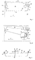
- eine schematische Teilschnittansicht durch einen Teil eines hinteren Bereiches eines Cabriolet-Fahrzeugs mit in Verdeckaufnahmestellung befindlicher Trennvorrichtung,
- Fig. 2
- eine Ansicht entsprechend der Fig. 1 mit in Gepäckaufnahmestellung befindlicher Trennvorrichtung,
- Fig. 3
- eine schematische Ansicht einer Antriebsvorrichtung,
- Fig. 4
- eine der Fig. 1 entsprechende perspektivische Ansicht und
- Fig. 5
- eine der Fig. 2 entsprechende perspektivische Ansicht.
- Gemäß den Figuren 1 und 4 weist ein Cabrioletfahrzeug eine Fahrzeugstruktur mit einer oben in einem Querträger 10 endenden und den im Heck des Fahrzeugs angeordneten Gepäckraum 12 von dem Fahrgastraum 14 trennenden Trennwand 16 auf, in der eine Durchladeöffnung 18 ausgebildet ist, durch die hindurch sperrige, im Gepäckraum 12 aufgenommene Gegenstände bis in den Fahrgastraum 14 hinein reichen können.
- In einem Abstand hinter dem Querträger 10 weist die Fahrzeugstruktur einen weiteren Querträger 20 (in Fig. 4 nicht dargestellt) auf, an dem eine Gepäckraumklappe 22 (Fig. 4) und eine Verdeckklappe 24 (Fig. 1) schwenkbar gelagert sind.
- In Fig. 1 stellt der Pfeil F die Vorwärtsrichtung des Fahrzeugs dar. Die Verdeckklappe 24 ist um eine Lagerachse A aufwärts schwenkbar.
- Ein nicht dargestelltes Verdeck des Fahrzeugs, das ein Stoffverdeck oder ein Hartschalenverdeck sein kann, liegt mit seinem Hinterrand, der meist als Spannbügel ausgebildet ist, im geschlossenen Zustand auf der geschlossenen Verdeckklappe 24 (Stellung gemäß Fig. 1) auf. Das Verdeck ist insgesamt, im Allgemeinen, im Bereich des Querträgers 10 an der Fahrzeugstruktur über einen Gelenkmechanismus befestigt. Zum Öffnen des Verdecks wird ein hinterer Bereich des Verdecks zunächst hochgeklappt, so dass Anschließend die Verdeckklappe 24 in Uhrzeigerrichtung hochgeklappt werden kann und eine in den Gepäckraum 12 reichende Öffnung freigibt. Durch diese Öffnung hindurch wird das Verdeck dann insgesamt abgesenkt und in einem Verdeckablageraum 26 abgelegt. Anschließend wird die Verdeckklappe 24 in Gegenuhrzeigerrichtung zurückgeschwenkt, so dass sie den Gepäckraum 12 bzw. den Verdeckablageraum 26 nach oben verschließt.
- Zur Abtrennung des Verdeckablageraums 26 von dem eigentlichen Gepäckraum 12 ist eine insgesamt mit 28 bezeichnete Trennvorrichtung vorgesehen, die sich quer über die Fahrzeugbreite erstreckt und ein vorderes Schwenkteil 30, ein Bodenteil 32 und eine hintere Schwenkklappe 34 aufweist.
- Das Schwenkteil 30 und die Schwenkklappe 34 sind in sich steife Bauteile, beispielsweise gespritzte Kunststoffteile, wohingegen das Bodenteil 32 zumindest einen sich quer über die Fahrzeugbreite erstreckenden biegsamen Bereich aufweist und vorteilhafterweise insgesamt durch eine Folie, einen Gewebestoff oder ein sonstiges biegsames, dünnes, gegebenenfalls elastisches Material, beispielsweise auch durch einen Teppich, gebildet ist.
- Das Schwenkteil 30 ist um eine Achse B in Richtung des Doppelpfeils schwenkbar unmittelbar am Querträger 10 oder mittels Schwenkzapfen beidseitig an der Fahrzeugstruktur angebracht. Gemäß Fig. 1 ist das Schwenkteil 30 aus einer im Wesentlichen senkrecht nach unten gerichteten Stellung, die einer Verdeckaufnahmestellung entspricht und in der das Schwenkteil 30 die Durchladeöffnung 18 teilweise überdeckt (Fig. 4) in Gegenuhrzeigerrichtung nach oben in eine etwa senkrechte Stellung bewegbar, die einer Gepäckaufnahmestellung entspricht und in der das Schwenkteil 30 bis knapp unterhalb der geschlossenen Verdeckklappe 24 reicht.
- Während das Schwenkteil 30 beispielsweise als eine insgesamt ebene Klappe ausgebildet sein kann, kann die Schwenkklappe 34 z. B. in sich gebogen ausgebildet werden und zum Gepäckraum 12 hin konvex sein. In der Stellung gemäß Fig. 1 befindet sich die Schwenkklappe 34 in ihrer Verdeckaufnahmestellung, in der sie sich vom Querträger 20 aus zunächst senkrecht nach unten und dann waagrecht in Richtung zur Trennwand 16 erstreckt. Die Schwenkklappe 34 ist aus der Stellung gemäß Fig. 1 um eine Achse C in Uhrzeigerrichtung um etwa 90° schwenkbar, so dass sie in der verschwenkten Stellung etwa an der Kontur des Querträgers 20 anliegt und bis zur Verdeckklappe 24 reicht.
- Das bevorzugt als Folie ausgebildete Bodenteil 32 ist an seinem in Fahrzeuglängsrichtung vorderen Rand am freien Rand des Schwenkteils 30 befestigt und an seinen rückwärtigen Rand am freien Rand der Schwenkklappe 34 befestigt. Die in Fahrzeuglängsrichtung gemessene Länge des Bodenteils 32 ist so, dass das Bodenteil 32 in der Verdeckaufnahmestellung gemäß Fig. 1 bzw. 4, in der der Verdeckablageraum 26 maximal ist und der Gepäckraum 12 durch den Verdeckablageraum 26 maximal verkleinert ist, in etwa gestreckt ist. In der in Fig. 2 dargestellten Gepäckaufnahmestellung der Trennvorrichtung 28, die bei geschlossenem Verdeck eingenommen wird, ist der Verdeckablageraum 26 minimal und im Wesentlichen nur in Folge des Durchhangs des Bodenteils 32 gebildet. Die gesamte Trennvorrichtung 28 kann derart ausgebildet sein, dass der Abstand der freien Enden des Schwenkteils und der Schwenkklappe in Gepäckaufnahmestellung etwa genauso groß ist wie in Verdeckaufnahmestellung (beispielsweise durch geringfügig weitere Schwenkbarkeit des Schwenkteils 30 in Gegenuhrzeigerrichtung gemäß Fig. 2, so dass der Verdeckablageraum 26 dann im Wesentlichen kein Volumen hat bzw. das Bodenteil 32 in sich straff ist. Auch bei durchhängendem Bodenteil 32 ist der Gepäckraum 12 nicht eingeschränkt, da das Bodenteil 32 von dem Gepäckraum 12 aufgenommenen Gepäckstücken nach oben gegen die Verdeckklappe 24 gedrängt werden kann. Ein Durchhängen des Bodenteils 32 kann auch dadurch vermieden werden, dass das Bodenteil 32 in Fahrzeuglängsrichtung elastisch dehnbar ist oder dass die das Bodenteil 32 bildende Folie durch Abwickeln von einer an einem der Klappenteile angebrachten Wickelwelle unter Spannung gehalten wird.
- Wie insbesondere aus Fig. 5 ersichtlich, ist der Gepäckraum 12 bei in Gepäckaufnahmestellung befindlicher Trennvorrichtung 28 nicht eingeschränkt und die Durchladeöffnung 18 ist voll zugänglich.
- Insbesondere das Schwenkteil 30 muss nicht zwingend ein flächiges Formteil sein, sondern kann lediglich durch einen Rahmen gebildet sein, an dem das Bodenteil 32 gehalten ist.
- Bei geeigneter Anbringung kann auch die Schwenkklappe 34 als ebenes flächiges Formteil oder als Rahmen ausgebildet sein, an dem das Bodenteil 32 gehalten wird.
- Im Folgenden wird eine Betätigungs- bzw. Antriebsvorrichtung 40 (Fig. 3) zum Verschwenken des Schwenkteils 30 und des Bodenteils 32 bzw. zum Bewegen der Trennvorrichtung 28 aus der Verdeckaufnahmestellung gemäß den Figuren 1 und 4 in die Gepäckaufnahmestellung gemäß den Figuren 2 und 5 erläutert.
- Das Schwenkteil 30 und die Schwenkklappe 34 sind vorteilhafterweise mittels Zapfen (Ausschnitt der Fig. 2) seitlich in entsprechenden Lageraufnahmen gelagert, die an der Fahrzeugstruktur ausgebildet sind. Zumindest an je einer Fahrzeugseite ist konzentrisch mit den Zapfen eine starr mit dem Schwenkteil 30 bzw. Schwenkklappe 34 verbundene Umlenkscheibe 44 konzentrisch zum Zapfen 42 angeordnet. An der Umlenkscheibe 44 ist ein Ende eines Zugmittels 46, beispielsweise die Seele eines Bowdenzugs, befestigt, der um einen Umfangsbereich der Umlenkscheibe 44 umläuft.
- Wie insbesondere aus dem Ausschnitt der Fig. 2 ersichtlich, ist die Anordnung derart, dass durch Ziehen am Zugmittel 46 die Schwenkklappe 34 in Uhrzeigerrichtung verschwenkt wird.
- Fig. 3 zeigt zusätzlich zur Umlenkscheibe 44 eine Umlenkscheibe 48 die starr mit dem Schwenkteil 30 verbunden ist, und um die ebenfalls ein Zugmittel 50 umläuft, wobei das Schwenkteil 30 bei Zug am Zugmittel 50 in Gegenuhrzeigerrichtung verschwenkt wird.
- Die beiden Zugmittel 46 und 50 sind über Umlenkrollen geführt und dann beispielsweise mit einer Zahnstange 54 verbunden, die mit dem Innengewinde eines Ritzels 56 kämmt, das von einem Elektromotor 58 drehangetrieben ist.
- Die an den von der Umlenkscheibe 44 bzw. 48 abgewandten Seiten der Schwenkklappe 34 bzw. des Schwenkteils 30 angeordneten Lagerzapfen sind vorteilhafterweise ebenfalls mit Bauteilen, beispielsweise Anschlagscheiben versehen, so dass sich Torsionsfedern zwischen den Anschlagscheiben und der Fahrzeugstruktur abstützen und das Schwenkteil 30 bzw. die Schwenkklappe 34 in die Verdeckaufnahmestellung gemäß Fig. 1 vorspannt. Durch Zug auf die Zugmittel 46 bzw. 50 gelangt die Trennvorrichtung 28 somit aus der Verdeckaufnahmestellung gemäß Figuren 1 bzw. 4 in die Gepäckaufnahmestellung gemäß Fig. 2 und 5. Werden umgekehrt die Zugmittel entlastet, so gelangt die Trennvorrichtung aus der Gepäckaufnahmestellung in die Verdeckaufnahmestellung.
- Es versteht sich, dass die Vorspannung und die Wirkrichtung der Zugmittel auch umgekehrt sein können. Die elektrische Betätigung der Verschwenkung hat den Vorteil, dass der Elektromotor 58 in eine Steuerfolge zum Öffnen und Schließen des Verdecks integriert werden kann, so dass die Vergrößerung bzw. Verkleinerung des Verdeckaufnahmeraums 26 synchronisiert mit der Öffnung bzw. dem Schließen des Verdecks erfolgt.
- Anstelle eines gemeinsamen Elektromotors 58 können auch getrennte Elektromotoren zum Verschwenken des Schwenkteils 30 bzw. der Schwenkklappe 34 vorgesehen sein.
- Bei der beschriebenen elastischen Vorspannung an jeweils einer Seite des Schwenkteils 30 bzw. der Schwenkklappe 34 und deren Betätigung an der jeweils anderen Seite ist ein gewisses Maß an Torsionssteifigkeit der genannten Bauteile erforderlich, dass dadurch vermindert werden kann, dass sich jeweils eine Welle über die gesamte Breite der Bauteile erstreckt. Anstelle des Elektromotors 58 kann auch ein Hydraulikzylinder verwendet werden.
- Des weiteren ist es möglich, die Bowdenzüge bzw. Zugmittel 46 und 50 direkt mit einem Teil des Gelenkmechanismus zu verbinden, der das Verdeck beim Öffnen und Schließen führt. Die Verbindung erfolgt dann vorteilhafterweise so, dass bei elastischer Verspannung der Trennvorrichtung 28 in Verdeckaufnahmestellung die Bewegung der Trennvorrichtung 28 in die Gepäckaufnahmestellung unmittelbar durch das Schließen des Verdecks erfolgt, wohingegen die Bewegung der Trennvorrichtung 28 aus der Gepäckaufnahmestellung in die Verdeckaufnahmestellung unmittelbar durch das Öffnen des Verdecks erfolgt.
- Alternativ können die Zugmittel 46 und 50 auch gemeinsam manuell betätigt werden.
- Um die Bewegbarkeit der Trennvorrichtung aus der Gepäckaufnahmestellung in die Verdeckaufnahmestellung sicherzustellen, kann eine Sensoreinrichtung vorgesehen sein, die bei in Gepäckaufnahmestellung befindlicher Trennvorrichtung den Raum, beispielsweise durch Ultraschall abtastet, der von der Trennvorrichtung beim Bewegen in die Verdeckaufnahmestellung überstrichen wird, oder die erfasst, ob das Schwenkteil und die Schwenkklappe sich bis in ihre Endstellungen bewegen.
- Die Erfindung ist in vielfältiger Weise abänderbar, solange der Grundgedanke realisiert ist, den Verdeckablageraum 26 durch mit Hilfe einer Betätigungs- bzw. Antriebsvorrichtung erfolgendes, vorteilhaft gleichzeitiges Verschwenken zweier Bauteile, die über ein flexibles Bodenteil verbunden sind, zwischen einem maximalen Volumen und einem minimalen Volumen hin und her zu verstellen.
-
- 10
- Querträger
- 12
- Gepäckraum
- 14
- Fahrgastraum
- 16
- Trennwand
- 18
- Durchladeöffnung
- 20
- Querträger
- 22
- Gepäckraumklappe
- 24
- Verdeckklappe
- 26
- Verdeckablageraum
- 28
- Trennvorrichtung
- 30
- Schwenkteil
- 32
- Bodenteil
- 34
- Schwenkklappe
- 40
- Antriebsvorrichtung
- 42
- Zapfen
- 44
- Umlenkscheibe
- 46
- Zugmittel
- 48
- Umlenkscheibe
- 50
- Zugmittel
- 52
- Umlenkrollen
- 54
- Zahnstange
- 56
- Ritzel
- 58
- Elektromotor
Claims (11)
- Cabriolet-Fahrzeug mit einem in einem Verdeckablageraum (26) ablegbaren Verdeck, welcher Verdeckablageraum (26) an den Fahrgastraum (14) nach hinten angrenzend durch eine Trennvorrichtung (28) von einem vorderen, oberen Bereich des Gepäckraums (12) des Fahrzeugs getrennt ist, wobei die Trennvorrichtung (28) ein vorderes, in sich im wesentlichen starres Schwenkteil (30), das mit der Fahrzeugstruktur um eine quer zur Fahrzeuglängsrichtung verlaufende Achse schwenkbar verbunden ist, eine hintere, in sich im wesentlichen starre Schwenkklappe (34), die mit der Fahrzeugstruktur um eine quer zur Fahrzeuglängsrichtung verlaufende Achse schwenkbar verbunden ist, und ein mit dem Schwenkteil (30) und der Schwenkklappe (34) verbundenes Bodenteil (32) aus zumindest teilweise flexiblem Material aufweist und durch Verschwenken des Schwenkteils (30) und der Schwenkklappe (34) in eine Verdeckaufnahmestellung, in der das Volumen des Verdeckaufnahmeraums maximal ist, und eine Gepäckaufnahmestellung, in der das Gepäckraumvolumen maximal ist, bringbar ist,
gekennzeichnet durch
eine Antriebsvorrichtung (40), mit der das Schwenkteil (30) und die Schwenklappe (34) zwischen der Verdeckaufnahmestellung und der Gepäckaufnahmestellung verschwenkbar sind. - Cabriolet-Fahrzeug nach Anspruch 1,
dadurch gekennzeichnet,
dass das Schwenkteil (30) und die Schwenkklappe (34) elastisch in der Verdeckaufnahmestellung vorgespannt sind und von der Antriebsvorrichtung (40) in die Gepäckaufnahmestellung schwenkbar sind. - Cabriolet-Fahrzeug nach Anspruch 1 oder 2,
dadurch gekennzeichnet,
dass die Antriebsvorrichtung (40) Zugelemente (46, 50) enthält, die um ein Umlenkbauteil (48, 44) des Schwenkteils (30) bzw. der Schwenkklappe (34) herumgeführt sind. - Cabriolet-Fahrzeug nach Anspruch 3,
dadurch gekennzeichnet,
dass die Zugelemente mit wenigstens einem Teil eines Verdeckklappmechanismus verbunden sind und durch dessen Bewegung betätigt werden. - Cabriolet-Fahrzeug nach einem der Ansprüche 1 bis 4,
dadurch gekennzeichnet,
dass die Antriebsvorrichtung (40) wenigstens einen elektrisch angesteuerten Aktor (58) enthält. - Cabriolet-Fahrzeug nach einem der Ansprüche 1 bis 5,
dadurch gekennzeichnet,
dass das Schwenkteil (30) an der Fahrzeugstruktur derart schwenkbar angebracht ist, dass es in der Verdeckaufnahmestellung eine in einer den Gepäckraum (12) zum Fahrgastraum (14) abtrennenden Trennwand (16) ausgebildete Durchladeöffnung (18) teilweise überdeckt und in der Gepäckaufnahmestellung nach oben derart verschwenkt ist, dass sich der an ihm befestigte Randbereich des Bodenteils (32) unmittelbar unter einer normalerweise geschlossenen Verdeckklappe (24) befindet. - Cabriolet-Fahrzeug nach Anspruch 6,
dadurch gekennzeichnet,
dass das Schwenkteil (30) als eine im wesentlichen ebene Klappe ausgebildet ist, an derem freien, sich quer zur Fahrzeuglängsrichtung erstreckenden Rand das Bodenteil (32) befestigt ist. - Cabriolet-Fahrzeug nach einem der Ansprüche 1 bis 7,
dadurch gekennzeichnet,
dass die Schwenkklappe (34) in ihrer abwärts verschwenkten Verdeckaufnahmestellung ausgehend von einem an der Oberseite des Gepäckraums (12) angeordneten Querträger (20) der Fahrzeugstruktur zunächst abwärts verläuft und dann nach vorne zu einem etwa waagerecht verlaufenden Bereich umgebogen ist, an deren freiem Rand das Bodenteil (32) befestigt ist. - Cabriolet-Fahrzeug nach Anspruch 8,
dadurch gekennzeichnet,
dass sich der freie Rand der Schwenkklappe (34) in deren Gepäckaufnahmestellung unmittelbar unter einer normalerweise geschlossenen Verdeckklappe (24) befindet. - Cabriolet-Fahrzeug nach einem der Ansprüche 1 bis 9,
dadurch gekennzeichnet,
dass das Bodenteil (32) durch eine in Fahrzeuglängsrichtung elastische Folie gebildet ist. - Cabriolet-Fahrzeug nach einem der Ansprüche 1 bis 10,
dadurch gekennzeichnet,
dass der Abstand zwischen den Bereichen des Schwenkteils (30) und der Schwenkklappe (34), an denen das Bodenteil (32) befestigt ist, in der Verdeckaufnahmestellung und in der Gepäckaufnahmestellung etwa gleich ist.
Applications Claiming Priority (1)
| Application Number | Priority Date | Filing Date | Title |
|---|---|---|---|
| DE102005029725.0A DE102005029725B4 (de) | 2005-06-24 | 2005-06-24 | Cabriolet-Fahrzeug mit einem in einem Verdeckablageraum ablegbaren Verdeck |
Publications (3)
| Publication Number | Publication Date |
|---|---|
| EP1736341A2 true EP1736341A2 (de) | 2006-12-27 |
| EP1736341A3 EP1736341A3 (de) | 2007-10-24 |
| EP1736341B1 EP1736341B1 (de) | 2011-08-24 |
Family
ID=36950342
Family Applications (1)
| Application Number | Title | Priority Date | Filing Date |
|---|---|---|---|
| EP06012913A Not-in-force EP1736341B1 (de) | 2005-06-24 | 2006-06-23 | Cabriolet-Fahrzeug mit einem in einem Verdeckablageraum ablegbaren Verdeck |
Country Status (3)
| Country | Link |
|---|---|
| EP (1) | EP1736341B1 (de) |
| AT (1) | ATE521494T1 (de) |
| DE (1) | DE102005029725B4 (de) |
Cited By (1)
| Publication number | Priority date | Publication date | Assignee | Title |
|---|---|---|---|---|
| EP3000639A1 (de) * | 2014-09-23 | 2016-03-30 | Audi Ag | Vorrichtung zur aufnahme eines verdecks eines kraftfahrzeugs in cabriolet-bauform und kraftfahrzeug |
Family Cites Families (10)
| Publication number | Priority date | Publication date | Assignee | Title |
|---|---|---|---|---|
| DE19541168C1 (de) * | 1995-11-04 | 1997-02-13 | Bayerische Motoren Werke Ag | Aufbewahrungseinrichtung |
| DE19723328B4 (de) * | 1997-06-04 | 2005-02-03 | Webasto Karosseriesysteme Gmbh | Umwandelbares Fahrzeugdach mit zusammenschiebbarem Verdeckkasten |
| DE29809006U1 (de) * | 1998-05-19 | 1999-05-12 | Wilhelm Karmann GmbH, 49084 Osnabrück | Cabriolet-Fahrzeug mit einem in einem Verdeckkasten ablegbaren Verdeck |
| DE29809008U1 (de) * | 1998-05-19 | 1999-05-12 | Wilhelm Karmann GmbH, 49084 Osnabrück | Kraftfahrzeug mit einem in einem Verdeckkasten ablegbaren Verdeck |
| DE19939505A1 (de) * | 1999-08-20 | 2001-03-15 | Karmann Gmbh W | Cabriolet-Fahrzeug mit einem in einem Verdeckkasten ablegbaren Dach |
| DE19957174C1 (de) * | 1999-11-27 | 2001-04-26 | Daimler Chrysler Ag | Cabrio-Fahrzeug |
| DE20012866U1 (de) * | 2000-07-25 | 2001-08-02 | Wilhelm Karmann GmbH, 49084 Osnabrück | Cabriolet-Fahrzeug mit einem über eine variable Trennvorrichtung abgeteilten Verdeckkasten |
| DE10138669A1 (de) * | 2000-08-24 | 2002-03-21 | Parat Automotive Schoenenbach | Verdeckkasten zur Aufnahme eines Falt- oder Klappverdecks von Cabriolets, Roadstern od. dgl. |
| DE10108338B4 (de) * | 2001-02-21 | 2005-01-20 | Valmet Automotive Oy | Ablageanordnung |
| DE10213553B4 (de) * | 2002-03-26 | 2008-12-24 | Webasto Ag | Cabriolet-Fahrzeug mit einer Prüfvorrichtung zur Überprüfung eines vorgegebenen Verdeckstauvolumens |
-
2005
- 2005-06-24 DE DE102005029725.0A patent/DE102005029725B4/de not_active Expired - Fee Related
-
2006
- 2006-06-23 EP EP06012913A patent/EP1736341B1/de not_active Not-in-force
- 2006-06-23 AT AT06012913T patent/ATE521494T1/de active
Cited By (2)
| Publication number | Priority date | Publication date | Assignee | Title |
|---|---|---|---|---|
| EP3000639A1 (de) * | 2014-09-23 | 2016-03-30 | Audi Ag | Vorrichtung zur aufnahme eines verdecks eines kraftfahrzeugs in cabriolet-bauform und kraftfahrzeug |
| US9694658B2 (en) | 2014-09-23 | 2017-07-04 | Audi Ag | Device for receiving a cover of a convertible motor vehicle and motor vehicle |
Also Published As
| Publication number | Publication date |
|---|---|
| EP1736341A3 (de) | 2007-10-24 |
| ATE521494T1 (de) | 2011-09-15 |
| DE102005029725A1 (de) | 2006-12-28 |
| EP1736341B1 (de) | 2011-08-24 |
| DE102005029725B4 (de) | 2016-12-22 |
Similar Documents
| Publication | Publication Date | Title |
|---|---|---|
| DE60124040T2 (de) | Raumabdeckung, Kofferraum und Antriebsvorrichtung | |
| DE10001958B4 (de) | Umwandelbares Fahrzeugdach | |
| DE10152944B4 (de) | Verdeck für ein Cabriolet-Fahrzeug | |
| EP1737689B1 (de) | Faltverdeck für ein cabriolet-fahrzeug sowie cabriolet-fahrzeug mit einem faltverdeck | |
| DE10134370A1 (de) | Abdeckvorrichtung für einen Verdeckkasten | |
| DE10146266C1 (de) | Klappverdeck für ein Cabriolet-Fahrzeug | |
| EP1826049A2 (de) | Cabriolet-Fahrzeug mit einem Hardtop-Fahrzeugdach | |
| EP1762414B1 (de) | Dach für Fahrzeuge mit offenem Aufbau | |
| DE10208185B4 (de) | Windabweiseranordnung für ein Fahrzeugdach | |
| WO2004037583A1 (de) | Bewegliches mehrfach geteiltes dach für ein kraftfahrzeug | |
| DE102008036005A1 (de) | Kraftfahrzeug | |
| DE102010004964A1 (de) | Cabriolet mit einem Windschottelement | |
| DE102007004180B4 (de) | Verstellbares Fahrzeugdach | |
| DE102005029725B4 (de) | Cabriolet-Fahrzeug mit einem in einem Verdeckablageraum ablegbaren Verdeck | |
| DE112006001632B4 (de) | Cabriolet-Kraftfahrzeug mit einem verstaubaren Dach | |
| DE10242502A1 (de) | Verstellbares Fahrzeugdach | |
| EP1588881B1 (de) | Kraftfahrzeug mit beweglichen Dachteilen | |
| DE20012866U1 (de) | Cabriolet-Fahrzeug mit einem über eine variable Trennvorrichtung abgeteilten Verdeckkasten | |
| DE10065248B4 (de) | Schwenkbare und verschiebbare Heckscheibe | |
| DE10137169A1 (de) | Trennvorrichtung zum Unterteilen eines Heckraumes eines Cabriolet-Fahrzeugs | |
| DE102013207954B4 (de) | Windschottsystem für ein Cabriolet | |
| EP1759905B1 (de) | Cabriolet-Fahrzeug mit einem in einem Verdeckablageraum ablegbaren Verdeck | |
| DE102006042285B4 (de) | Anordnung eines Verdeckkastendeckels an einem Kraftfahrzeug | |
| DE102023136909A1 (de) | Cabriolet-fahrzeug mit abdeckelementen | |
| DE102005009720A1 (de) | Verdeck für ein Cabriolet-Fahrzeug |
Legal Events
| Date | Code | Title | Description |
|---|---|---|---|
| PUAI | Public reference made under article 153(3) epc to a published international application that has entered the european phase |
Free format text: ORIGINAL CODE: 0009012 |
|
| AK | Designated contracting states |
Kind code of ref document: A2 Designated state(s): AT BE BG CH CY CZ DE DK EE ES FI FR GB GR HU IE IS IT LI LT LU LV MC NL PL PT RO SE SI SK TR |
|
| AX | Request for extension of the european patent |
Extension state: AL BA HR MK YU |
|
| PUAL | Search report despatched |
Free format text: ORIGINAL CODE: 0009013 |
|
| AK | Designated contracting states |
Kind code of ref document: A3 Designated state(s): AT BE BG CH CY CZ DE DK EE ES FI FR GB GR HU IE IS IT LI LT LU LV MC NL PL PT RO SE SI SK TR |
|
| AX | Request for extension of the european patent |
Extension state: AL BA HR MK YU |
|
| 17P | Request for examination filed |
Effective date: 20071127 |
|
| 17Q | First examination report despatched |
Effective date: 20080109 |
|
| AKX | Designation fees paid |
Designated state(s): AT BE BG CH CY CZ DE DK EE ES FI FR GB GR HU IE IS IT LI LT LU LV MC NL PL PT RO SE SI SK TR |
|
| 19U | Interruption of proceedings before grant |
Effective date: 20090629 |
|
| 19W | Proceedings resumed before grant after interruption of proceedings |
Effective date: 20101201 |
|
| GRAP | Despatch of communication of intention to grant a patent |
Free format text: ORIGINAL CODE: EPIDOSNIGR1 |
|
| GRAS | Grant fee paid |
Free format text: ORIGINAL CODE: EPIDOSNIGR3 |
|
| GRAA | (expected) grant |
Free format text: ORIGINAL CODE: 0009210 |
|
| RIN1 | Information on inventor provided before grant (corrected) |
Inventor name: THOENELT, RALF |
|
| AK | Designated contracting states |
Kind code of ref document: B1 Designated state(s): AT BE BG CH CY CZ DE DK EE ES FI FR GB GR HU IE IS IT LI LT LU LV MC NL PL PT RO SE SI SK TR |
|
| REG | Reference to a national code |
Ref country code: GB Ref legal event code: FG4D Free format text: NOT ENGLISH |
|
| REG | Reference to a national code |
Ref country code: CH Ref legal event code: EP |
|
| REG | Reference to a national code |
Ref country code: IE Ref legal event code: FG4D Free format text: LANGUAGE OF EP DOCUMENT: GERMAN |
|
| REG | Reference to a national code |
Ref country code: DE Ref legal event code: R096 Ref document number: 502006010057 Country of ref document: DE Effective date: 20111020 |
|
| REG | Reference to a national code |
Ref country code: NL Ref legal event code: VDEP Effective date: 20110824 |
|
| LTIE | Lt: invalidation of european patent or patent extension |
Effective date: 20110824 |
|
| PG25 | Lapsed in a contracting state [announced via postgrant information from national office to epo] |
Ref country code: NL Free format text: LAPSE BECAUSE OF FAILURE TO SUBMIT A TRANSLATION OF THE DESCRIPTION OR TO PAY THE FEE WITHIN THE PRESCRIBED TIME-LIMIT Effective date: 20110824 Ref country code: SE Free format text: LAPSE BECAUSE OF FAILURE TO SUBMIT A TRANSLATION OF THE DESCRIPTION OR TO PAY THE FEE WITHIN THE PRESCRIBED TIME-LIMIT Effective date: 20110824 Ref country code: IS Free format text: LAPSE BECAUSE OF FAILURE TO SUBMIT A TRANSLATION OF THE DESCRIPTION OR TO PAY THE FEE WITHIN THE PRESCRIBED TIME-LIMIT Effective date: 20111224 Ref country code: PT Free format text: LAPSE BECAUSE OF FAILURE TO SUBMIT A TRANSLATION OF THE DESCRIPTION OR TO PAY THE FEE WITHIN THE PRESCRIBED TIME-LIMIT Effective date: 20111226 Ref country code: LT Free format text: LAPSE BECAUSE OF FAILURE TO SUBMIT A TRANSLATION OF THE DESCRIPTION OR TO PAY THE FEE WITHIN THE PRESCRIBED TIME-LIMIT Effective date: 20110824 Ref country code: FI Free format text: LAPSE BECAUSE OF FAILURE TO SUBMIT A TRANSLATION OF THE DESCRIPTION OR TO PAY THE FEE WITHIN THE PRESCRIBED TIME-LIMIT Effective date: 20110824 |
|
| PG25 | Lapsed in a contracting state [announced via postgrant information from national office to epo] |
Ref country code: GR Free format text: LAPSE BECAUSE OF FAILURE TO SUBMIT A TRANSLATION OF THE DESCRIPTION OR TO PAY THE FEE WITHIN THE PRESCRIBED TIME-LIMIT Effective date: 20111125 Ref country code: CY Free format text: LAPSE BECAUSE OF FAILURE TO SUBMIT A TRANSLATION OF THE DESCRIPTION OR TO PAY THE FEE WITHIN THE PRESCRIBED TIME-LIMIT Effective date: 20110824 Ref country code: SI Free format text: LAPSE BECAUSE OF FAILURE TO SUBMIT A TRANSLATION OF THE DESCRIPTION OR TO PAY THE FEE WITHIN THE PRESCRIBED TIME-LIMIT Effective date: 20110824 Ref country code: LV Free format text: LAPSE BECAUSE OF FAILURE TO SUBMIT A TRANSLATION OF THE DESCRIPTION OR TO PAY THE FEE WITHIN THE PRESCRIBED TIME-LIMIT Effective date: 20110824 Ref country code: PL Free format text: LAPSE BECAUSE OF FAILURE TO SUBMIT A TRANSLATION OF THE DESCRIPTION OR TO PAY THE FEE WITHIN THE PRESCRIBED TIME-LIMIT Effective date: 20110824 |
|
| REG | Reference to a national code |
Ref country code: IE Ref legal event code: FD4D |
|
| PG25 | Lapsed in a contracting state [announced via postgrant information from national office to epo] |
Ref country code: SK Free format text: LAPSE BECAUSE OF FAILURE TO SUBMIT A TRANSLATION OF THE DESCRIPTION OR TO PAY THE FEE WITHIN THE PRESCRIBED TIME-LIMIT Effective date: 20110824 Ref country code: CZ Free format text: LAPSE BECAUSE OF FAILURE TO SUBMIT A TRANSLATION OF THE DESCRIPTION OR TO PAY THE FEE WITHIN THE PRESCRIBED TIME-LIMIT Effective date: 20110824 Ref country code: IE Free format text: LAPSE BECAUSE OF FAILURE TO SUBMIT A TRANSLATION OF THE DESCRIPTION OR TO PAY THE FEE WITHIN THE PRESCRIBED TIME-LIMIT Effective date: 20110824 |
|
| PG25 | Lapsed in a contracting state [announced via postgrant information from national office to epo] |
Ref country code: IT Free format text: LAPSE BECAUSE OF FAILURE TO SUBMIT A TRANSLATION OF THE DESCRIPTION OR TO PAY THE FEE WITHIN THE PRESCRIBED TIME-LIMIT Effective date: 20110824 Ref country code: RO Free format text: LAPSE BECAUSE OF FAILURE TO SUBMIT A TRANSLATION OF THE DESCRIPTION OR TO PAY THE FEE WITHIN THE PRESCRIBED TIME-LIMIT Effective date: 20110824 Ref country code: EE Free format text: LAPSE BECAUSE OF FAILURE TO SUBMIT A TRANSLATION OF THE DESCRIPTION OR TO PAY THE FEE WITHIN THE PRESCRIBED TIME-LIMIT Effective date: 20110824 |
|
| PG25 | Lapsed in a contracting state [announced via postgrant information from national office to epo] |
Ref country code: DK Free format text: LAPSE BECAUSE OF FAILURE TO SUBMIT A TRANSLATION OF THE DESCRIPTION OR TO PAY THE FEE WITHIN THE PRESCRIBED TIME-LIMIT Effective date: 20110824 |
|
| PLBE | No opposition filed within time limit |
Free format text: ORIGINAL CODE: 0009261 |
|
| STAA | Information on the status of an ep patent application or granted ep patent |
Free format text: STATUS: NO OPPOSITION FILED WITHIN TIME LIMIT |
|
| 26N | No opposition filed |
Effective date: 20120525 |
|
| REG | Reference to a national code |
Ref country code: DE Ref legal event code: R097 Ref document number: 502006010057 Country of ref document: DE Effective date: 20120525 |
|
| BERE | Be: lapsed |
Owner name: WILHELM KARMANN G.M.B.H. Effective date: 20120630 |
|
| PG25 | Lapsed in a contracting state [announced via postgrant information from national office to epo] |
Ref country code: MC Free format text: LAPSE BECAUSE OF NON-PAYMENT OF DUE FEES Effective date: 20120630 |
|
| REG | Reference to a national code |
Ref country code: CH Ref legal event code: PL |
|
| REG | Reference to a national code |
Ref country code: CH Ref legal event code: PL |
|
| PG25 | Lapsed in a contracting state [announced via postgrant information from national office to epo] |
Ref country code: CH Free format text: LAPSE BECAUSE OF NON-PAYMENT OF DUE FEES Effective date: 20120630 Ref country code: ES Free format text: LAPSE BECAUSE OF FAILURE TO SUBMIT A TRANSLATION OF THE DESCRIPTION OR TO PAY THE FEE WITHIN THE PRESCRIBED TIME-LIMIT Effective date: 20111205 Ref country code: LI Free format text: LAPSE BECAUSE OF NON-PAYMENT OF DUE FEES Effective date: 20120630 Ref country code: BE Free format text: LAPSE BECAUSE OF NON-PAYMENT OF DUE FEES Effective date: 20120630 |
|
| PG25 | Lapsed in a contracting state [announced via postgrant information from national office to epo] |
Ref country code: BG Free format text: LAPSE BECAUSE OF FAILURE TO SUBMIT A TRANSLATION OF THE DESCRIPTION OR TO PAY THE FEE WITHIN THE PRESCRIBED TIME-LIMIT Effective date: 20111124 |
|
| PGFP | Annual fee paid to national office [announced via postgrant information from national office to epo] |
Ref country code: GB Payment date: 20130620 Year of fee payment: 8 |
|
| REG | Reference to a national code |
Ref country code: AT Ref legal event code: MM01 Ref document number: 521494 Country of ref document: AT Kind code of ref document: T Effective date: 20120623 |
|
| PGFP | Annual fee paid to national office [announced via postgrant information from national office to epo] |
Ref country code: FR Payment date: 20130703 Year of fee payment: 8 |
|
| REG | Reference to a national code |
Ref country code: DE Ref legal event code: R082 Ref document number: 502006010057 Country of ref document: DE Representative=s name: KRONTHALER, SCHMIDT & COLL. PATENTANWALTSKANZL, DE |
|
| PG25 | Lapsed in a contracting state [announced via postgrant information from national office to epo] |
Ref country code: AT Free format text: LAPSE BECAUSE OF NON-PAYMENT OF DUE FEES Effective date: 20120623 |
|
| REG | Reference to a national code |
Ref country code: DE Ref legal event code: R081 Ref document number: 502006010057 Country of ref document: DE Owner name: VALMET AUTOMOTIVE OY, FI Free format text: FORMER OWNER: WILHELM KARMANN GMBH, 49084 OSNABRUECK, DE Effective date: 20131022 Ref country code: DE Ref legal event code: R081 Ref document number: 502006010057 Country of ref document: DE Owner name: VALMET AUTOMOTIVE OY, FI Free format text: FORMER OWNER: WILHELM KARMANN GMBH, 49084 OSNABRUECK, DE Effective date: 20110829 Ref country code: DE Ref legal event code: R082 Ref document number: 502006010057 Country of ref document: DE Representative=s name: KRONTHALER, SCHMIDT & COLL. PATENTANWALTSKANZL, DE Effective date: 20131022 |
|
| PG25 | Lapsed in a contracting state [announced via postgrant information from national office to epo] |
Ref country code: TR Free format text: LAPSE BECAUSE OF FAILURE TO SUBMIT A TRANSLATION OF THE DESCRIPTION OR TO PAY THE FEE WITHIN THE PRESCRIBED TIME-LIMIT Effective date: 20110824 |
|
| PG25 | Lapsed in a contracting state [announced via postgrant information from national office to epo] |
Ref country code: LU Free format text: LAPSE BECAUSE OF NON-PAYMENT OF DUE FEES Effective date: 20120623 |
|
| PG25 | Lapsed in a contracting state [announced via postgrant information from national office to epo] |
Ref country code: HU Free format text: LAPSE BECAUSE OF FAILURE TO SUBMIT A TRANSLATION OF THE DESCRIPTION OR TO PAY THE FEE WITHIN THE PRESCRIBED TIME-LIMIT Effective date: 20060623 |
|
| REG | Reference to a national code |
Ref country code: GB Ref legal event code: 732E Free format text: REGISTERED BETWEEN 20140925 AND 20141001 |
|
| REG | Reference to a national code |
Ref country code: FR Ref legal event code: TP Owner name: VALMET AUTOMOTIVE OY, FI Effective date: 20150105 |
|
| GBPC | Gb: european patent ceased through non-payment of renewal fee |
Effective date: 20140623 |
|
| REG | Reference to a national code |
Ref country code: FR Ref legal event code: ST Effective date: 20150227 |
|
| PG25 | Lapsed in a contracting state [announced via postgrant information from national office to epo] |
Ref country code: GB Free format text: LAPSE BECAUSE OF NON-PAYMENT OF DUE FEES Effective date: 20140623 Ref country code: FR Free format text: LAPSE BECAUSE OF NON-PAYMENT OF DUE FEES Effective date: 20140630 |
|
| PGFP | Annual fee paid to national office [announced via postgrant information from national office to epo] |
Ref country code: DE Payment date: 20160721 Year of fee payment: 11 |
|
| REG | Reference to a national code |
Ref country code: DE Ref legal event code: R119 Ref document number: 502006010057 Country of ref document: DE |
|
| PG25 | Lapsed in a contracting state [announced via postgrant information from national office to epo] |
Ref country code: DE Free format text: LAPSE BECAUSE OF NON-PAYMENT OF DUE FEES Effective date: 20180103 |