EP1736376A2 - Module pré assemblé pour un véhicule cabriolet - Google Patents
Module pré assemblé pour un véhicule cabriolet Download PDFInfo
- Publication number
- EP1736376A2 EP1736376A2 EP20060012907 EP06012907A EP1736376A2 EP 1736376 A2 EP1736376 A2 EP 1736376A2 EP 20060012907 EP20060012907 EP 20060012907 EP 06012907 A EP06012907 A EP 06012907A EP 1736376 A2 EP1736376 A2 EP 1736376A2
- Authority
- EP
- European Patent Office
- Prior art keywords
- locking
- component group
- group according
- rollover
- module
- Prior art date
- Legal status (The legal status is an assumption and is not a legal conclusion. Google has not performed a legal analysis and makes no representation as to the accuracy of the status listed.)
- Granted
Links
- 230000000903 blocking effect Effects 0.000 claims description 24
- 238000006073 displacement reaction Methods 0.000 claims description 9
- 230000008018 melting Effects 0.000 claims description 8
- 238000002844 melting Methods 0.000 claims description 8
- 239000003380 propellant Substances 0.000 claims description 8
- 239000000155 melt Substances 0.000 claims description 3
- 230000003213 activating effect Effects 0.000 claims 1
- 230000013011 mating Effects 0.000 claims 1
- 238000005096 rolling process Methods 0.000 claims 1
- 230000007246 mechanism Effects 0.000 abstract description 3
- 210000002414 leg Anatomy 0.000 description 31
- 238000004519 manufacturing process Methods 0.000 description 8
- 230000009471 action Effects 0.000 description 5
- 239000000463 material Substances 0.000 description 5
- 230000006835 compression Effects 0.000 description 4
- 238000007906 compression Methods 0.000 description 4
- 230000000694 effects Effects 0.000 description 4
- 230000036961 partial effect Effects 0.000 description 4
- 230000002093 peripheral effect Effects 0.000 description 4
- 238000003860 storage Methods 0.000 description 4
- 238000004873 anchoring Methods 0.000 description 3
- 230000008901 benefit Effects 0.000 description 3
- 238000004146 energy storage Methods 0.000 description 3
- 238000005304 joining Methods 0.000 description 3
- 230000004044 response Effects 0.000 description 3
- 230000000284 resting effect Effects 0.000 description 3
- 230000000452 restraining effect Effects 0.000 description 3
- 238000011144 upstream manufacturing Methods 0.000 description 3
- 230000004913 activation Effects 0.000 description 2
- 238000010276 construction Methods 0.000 description 2
- 230000006870 function Effects 0.000 description 2
- 238000005192 partition Methods 0.000 description 2
- 230000009467 reduction Effects 0.000 description 2
- 230000002829 reductive effect Effects 0.000 description 2
- 230000004083 survival effect Effects 0.000 description 2
- 239000000725 suspension Substances 0.000 description 2
- 238000012360 testing method Methods 0.000 description 2
- 241001295925 Gegenes Species 0.000 description 1
- 230000004308 accommodation Effects 0.000 description 1
- 230000000712 assembly Effects 0.000 description 1
- 238000000429 assembly Methods 0.000 description 1
- 230000004888 barrier function Effects 0.000 description 1
- 230000008859 change Effects 0.000 description 1
- 230000003750 conditioning effect Effects 0.000 description 1
- 238000005520 cutting process Methods 0.000 description 1
- 230000006735 deficit Effects 0.000 description 1
- 230000003111 delayed effect Effects 0.000 description 1
- 238000001514 detection method Methods 0.000 description 1
- 238000009826 distribution Methods 0.000 description 1
- 238000009434 installation Methods 0.000 description 1
- 230000003993 interaction Effects 0.000 description 1
- 238000002955 isolation Methods 0.000 description 1
- 239000002184 metal Substances 0.000 description 1
- 238000003801 milling Methods 0.000 description 1
- 230000004048 modification Effects 0.000 description 1
- 238000012986 modification Methods 0.000 description 1
- 230000002787 reinforcement Effects 0.000 description 1
- 239000012858 resilient material Substances 0.000 description 1
- 230000002441 reversible effect Effects 0.000 description 1
- 230000001960 triggered effect Effects 0.000 description 1
- 210000000689 upper leg Anatomy 0.000 description 1
- 239000013585 weight reducing agent Substances 0.000 description 1
- 238000003466 welding Methods 0.000 description 1
Images









Classifications
-
- B—PERFORMING OPERATIONS; TRANSPORTING
- B60—VEHICLES IN GENERAL
- B60R—VEHICLES, VEHICLE FITTINGS, OR VEHICLE PARTS, NOT OTHERWISE PROVIDED FOR
- B60R21/00—Arrangements or fittings on vehicles for protecting or preventing injuries to occupants or pedestrians in case of accidents or other traffic risks
- B60R21/02—Occupant safety arrangements or fittings, e.g. crash pads
- B60R21/13—Roll-over protection
-
- B—PERFORMING OPERATIONS; TRANSPORTING
- B60—VEHICLES IN GENERAL
- B60R—VEHICLES, VEHICLE FITTINGS, OR VEHICLE PARTS, NOT OTHERWISE PROVIDED FOR
- B60R21/00—Arrangements or fittings on vehicles for protecting or preventing injuries to occupants or pedestrians in case of accidents or other traffic risks
- B60R21/02—Occupant safety arrangements or fittings, e.g. crash pads
- B60R21/13—Roll-over protection
- B60R2021/132—Roll bars for convertible vehicles
- B60R2021/134—Roll bars for convertible vehicles movable from a retracted to a protection position
- B60R2021/135—Roll bars for convertible vehicles movable from a retracted to a protection position automatically during an accident
Definitions
- the invention relates to a group of components for a convertible vehicle according to the closer defined in the preamble of claim 1. Art.
- a rollover body such as. B. have a roll bar, which is associated with a single vehicle seat or more vehicle seats and is hidden in its rest position in a vehicle-mounted cassette, from which it is suddenly recognizable upon detection of an accident of the vehicle in an upper support position and lockable in this support position.
- roll bars are typically made of a U-shaped bracket whose tubular legs are vertically guided in stanchions of a vehicle-fixed module. Inside each leg, a coil spring is arranged, which is held by a holding device under bias, which is releasable in response to a crash signal of the vehicle sensor, whereby the roll bar under the action of the spring extended in tenths of a second and locked in its supporting position by a suitable locking device becomes.
- the two tubular legs are connected to each other by a transverse yoke over which a padded impact element is usually pushed.
- the DE 103 18 594 A1 describes a further developed rollover protection device for a motor vehicle with a roll bar, which is formed at least approximately U-shaped with a transverse yoke and side legs spanning substantially the vehicle width.
- a central, actuated by an actuator holding and triggering device for the roll bar and a displacement of the legs along the guide means synchronizing means is provided.
- a through-opening is provided between the legs of the roll bar.
- a rollover protection device associated with each vehicle seat consisting of a cassette fixed to the vehicle, guided in the cassette and guided rollover body in the form of extending over the entire width of the cassette profile body, a locking device for self-locking the extension movement and a spring drive system for extending the profile hanger body and with a mechanical holding device for holding the rollover body in a resting state and against the biasing force of a compression spring of the spring drive system.
- Such a prefabricated partition can according to the DE 10 2004 016 362 A1 be equipped with additional units. It is proposed, in contrast to a vehicle-mounted attachment of a belt system such. B. according to the DE 93 04 820 U1 to attach safety harness machines to the prefabricated partition.
- a transverse stiffening structure may need to be installed in the vehicle with a through-hole in combination with a rollover protection system, a hood and possibly connected to the top mechanism body components and a seat system.
- these assemblies are vendor parts, which must be combined during the final assembly time-consuming, whereby the lead time of vehicles in the final assembly is affected.
- the component group comprises seat elements and a restraint belt system integrated in the vehicle-mounted first module with belt guides for at least one restraint belt and forms a constructional unit which can be tested for functionality outside the vehicle.
- the component group according to the invention thus forms a compact unit representing a single module, which can be completed outside the vehicle and can be inserted into the intended vehicle body in a single assembly step.
- This separately completed unit which can for example be supplied by external suppliers, can be fastened to the vehicle body in a simple manner preferably by screwing, but possibly also by welding, and only has to be connected to corresponding connections for the electrical and hydraulic supply as well as for data exchange with sensors and control units of the rest of the vehicle become.
- the component group according to the invention is particularly advantageous in terms of safety in that the interaction of seat elements and restraint belt system outside the vehicle can be tested.
- the combination of the top with an externally manufactured transverse stiffening structure, in which the rollover protection system is integrated, is particularly advantageous in that moving parts associated with the top mechanism, which are associated with the transverse stiffening, a seat back structure or the rollover protection system, together outside the Vehicle can be completed and tested. This also applies to seat elements which interact with the rollover protection system.
- Seat elements of the component group can represent seat backrest storage and seat base stock and headrest receptacles in the simplest way, depending on the configuration of the convertible vehicle with a two-seat or three-seat row following the inventive component group and depending on the configuration of the seats themselves on the first vehicle-fixed module of the rollover protection system and / or may be attached to the transverse stiffening structure.
- the final assembly of the convertible vehicle is further simplified in that both a multi-joint to the opening of the body cover and drive members for the body cover are already integrated into the unit, which in particular covers, their Movement also includes the movement of the relevant body cover included, outside the vehicle in the pre-assembled state can be checked. Furthermore, there are no further assembly steps for the rear body cover.
- the rear body cover can be both a pure top compartment lid and a combined top compartment lid boot lid.
- a through-loading opening is arranged between the rear-side receiving space and the passenger compartment, which facilitates the accommodation of bulky objects in the vehicle.
- the rear-side receiving space can be a convertible top storage space as well as a pure luggage receiving space or a combined top and luggage receiving space.
- the components of a safety belt system such.
- a belt retractor and an upper seat belt guide can be easily integrated into the built-in state vehicle-mounted components of the component group via appropriate receptacles, which can be provided without any special effort in the production of the profiles of the first module or the transverse stiffening structure.
- the restraint belt system may comprise not only seat belts for adult adult people, but also child seat restraints, wherein in a particularly advantageous embodiment an upper anchorage point for a child seat restraint belt, also referred to as a toptether attachment, on a vehicle-mounted component of the component group, in particular the Rollover protection system is arranged.
- a rollover protection device is associated with a rollover body in each case a seat, the rollover protection devices of two vehicle seats of a row of seats are preferably arranged in each case in the opposite direction substantially off-center to the associated vehicle seat.
- the rollover protection system thus has for each vehicle seat on a rollover protection device which is driven independently of the rollover protection device of another seat, so that tilting of the extendable module in its extension movement and thus impairment of the reliability can be avoided.
- An eccentric arrangement of the rollover protection devices that is, their components predominantly in the region of a vehicle side facing side of The vehicle seat concerned are arranged, advantageously allows the arrangement of a generous through-opening between the vehicle seats.
- the rollover body may be rod-like, having in its interior an axial receiving channel for a spring energy accumulator of the drive system.
- the rod-like configuration of the rollover body with an axial receiving channel for the spring energy storage has the advantage that the spring energy storage, which is required for the displacement of the rollover body, can be integrated into the rollover body, wherein the shape of the inner contour of the rollover body corresponding to the shape of the spring pressure accumulator on a additional spring guide can be omitted.
- the spring energy accumulator can be designed as a compression spring, which is supported on the body-mounted first module and the rollover body. Deviating from this, however, a tension spring may be provided, which is installed, for example, between a coaxially extending to the interior of the roll bar rod and the held by the releasable holding device rollover body biased that the rollover body after release by the releasable holding device on ground the tensile force of the spring is transferred into an upper support position.
- such a tension spring may also be held on a bolt fixed to the body, which extends, for example, through a longitudinal slot into the interior of the roll bar, so that the spring energy store is completely guided by the rollover body without further guidance.
- a complete guidance of the spring force accumulator by the rollover body is also possible with a compression spring, which between a trained on the rollover body stop and a extending through a recess in the rollover body-mounted stop, which may be formed, for example, as a bolt with a spring plate, under compressive stress is installed.
- each rollover protection device is achieved, which optionally together with the eccentric arrangement of the rollover protection devices, for example, behind the rear seats offers a large through-loading facility for bulky goods between a vehicle interior and a rear-side receiving space.
- the rollover body of the rollover protection system is designed as a roll bar, which is substantially overstretching the vehicle width and at least approximately U-shaped with a traverse and side leg members.
- the synchronization device is preferably designed with a synchronization shaft, which is mounted stationary parallel to the traverse of the roll bar in the installed state and is connected to the leg elements in each case via a tooth profile, which engages in a locking strip formed on the associated leg element.
- the synchronization wave can according to the DE 103 18 594 A1 be formed synchronization shaft described.
- these may have a tubular profile, in which in rest position of the rollover body at least one upper end portion and in supporting position, a lower end portion of the rollover body are added.
- the guide means of the rollover body forming tube profile is arranged with its lower edge opposite a foot member of the first module spaced.
- a foot member of the first module spaced.
- To connect the pipe profile with the foot member of the first module can be provided laterally of the pipe profile fastened connection profile, which may be, for example, a U-profile or a box section.
- the guide means of the vehicle-mounted first module, as well as the components of the extendable module, in particular the rollover body, be made of inexpensive extruded profiles.
- the serving as a guide device tube profile are combined in a simple manner with other functional elements, such. B. with a locking device of the locking device, which may be supported on the pipe profile.
- the tube profile z in a very cost-effective design.
- Example have a peripheral recess for receiving the latching device supported thereon of the locking device, wherein the latching device is held in the direction of movement of the rollover body form-fitting manner on the tube profile and not further connected to the tube profile.
- the releasable holding device for holding the second module with the rollover body in its rest position can basically be of known type and z. B. comprise a pivotable about a fixed axis of rotation mounted locking element, which is formed with a pawl portion which is in the rest position of the rollover body in engagement with a locking element counter-body on the rollover body.
- the locking element can be pivoted in a crash signal such that the pawl portion for transferring the rollover body in its supporting position is disengaged locking element-opposing body.
- Such an embodiment of the releasable holding device and the rollover protection device equipped therewith enables a secure and cost-effective locking of the rollover body in its rest position, wherein the holding device can advantageously be realized with few components to be manufactured without great precision.
- a further advantageous embodiment according to the invention provides that the pivotable locking element, which engages with a locking element-counter body of the second module in the rest position of the rollover body and in the event of a crash releases the rollover body for transfer to its support position, in the rest position by a in Crash case fusible melt insert of the actuator is held.
- fuse link to hold the locking element and to cancel the locking position in the event of a crash ensures a reliable and quick release of the rollover body in a simple and cost-effective manner. If only the pivotally mounted and standing in the rest position of the rollover body in engagement with the locking element counter body locking element must be held by the fuse link, the fuse link can be designed for much lower forces than it is designed for direct holding of the second module or the rollover body would. The correspondingly reduced dimensioning of the fuse insert in turn allows a rapid melting and thus cutting through the components connected thereto, whereby the triggering of the rollover body can be done in a very short time.
- the melting insert can in principle have any shape and z.
- the pivotable locking element can be configured in principle in any form in the holding device of the rollover protection system according to the invention.
- a locking member which the locking element in holds a rollover body holding blocking position or releases. It can be provided that the locking member is biased in the locked position against a seat which is held by the fusible melt insert of the actuator by means of an energy storage device. In a detected crash, the seat of the locking member can be lifted in a flash by melting the fuse link, so that the biased locking member escape in the direction of the lifted seat and can release the locking element.
- the locking element z. B. radially directly against a seat, which is held by a fusible fuse in the rest position of the system to be pressed.
- a fusible fuse in the rest position of the system to be pressed.
- the locking element in the rest position in the rotational direction radially connected to a base body by a fuse link that it exerts a tensile force against the base body, the main body carries one end of the fuse link and the locking element the other end of the fuse link.
- the locking element may be held in the rest position in a stop position, from which it can be transferred in the event of a crash by an actuator with a pyrotechnic propellant in a rotational position.
- the locking device has at least one first latching device which can be brought into operative connection with a second latching device for supporting the second module and which permits movement of the second module starting from its rest position in the direction of its supporting position.
- the first locking device may comprise a pawl with a tooth profile in a simple embodiment, while the second locking device is formed with a the geometry of the tooth profile of the first latching device adapted locking bar.
- the pawl is preferably spring-mounted in the direction of the locking strip.
- the locking device for automatic locking of the extendable second module may be formed in its partially or fully extended position with a first and a second latching device, wherein one of the latching devices is connected to one of the modules and eccentrically mounted about an axis of rotation , with a Has tooth profile profiled locking body and wherein the respective other locking device is designed as a the locking body facing surface of the respective other module with which the tooth profile is in an operative position of the locking body, in which a movement of the second module is prevented in the direction of its rest position in frictional engagement ,
- Such configured locking device has the advantage of a simple structure with few, without high precision requirements to be manufactured components.
- the second locking device of the rollover protection system can be designed as a simple surface of a component of the modules, which is available without further manufacturing steps, whereas in conventional rollover protection systems consuming and executed with tooth profiles locking devices are provided with a tooth profile of a pawl for locking of the rollover protection system must be engaged.
- the locking device may be advantageously configured such that a locking element of the first latching device is designed as a toothed profile element, which in locked Operating state of the locking device is operatively connected both with the synchronization shaft and with at least one of the locking strips of the leg elements.
- the locking device is thus arranged in a region of the component group, in the rest position of the second module is occupied by the roll bar in the vehicle transverse direction, whereby between the guide means of the leg members, a large through-opening can be provided.
- the locking device which uses the components of the synchronization device, the number of components is reduced.
- a first component group 1 for a convertible vehicle which has a transverse stiffening structure 10 which, when installed in a body of the cabriolet vehicle, has an occupant space 13 symbolically indicated with respect to its position in FIG. 1 from a rear-side receiving space 12 separates.
- the transverse reinforcement structure 10 is formed integrally with a rollover protection system 11, which has a first module 4 fixed to the body with guide means 30 for a second module 5 movable between a lowered rest position and an elevated support position with a rollover body 6 configured here as a roll bar.
- the roll bar 6 extends in the vehicle transverse direction substantially over the vehicle width and is formed in the embodiment shown in Fig. 1 approximately U-shaped with a crossbar 63 and side leg members 64A, 64B in one piece.
- the leg members 64A and 64B each cooperate with one of two presently identical guide means 30 of the first module 4 and are moved in an outward movement of the second module 5 in a direction of movement shown by an arrow Z in Fig. 1, starting from the rest position shown.
- a central holding device 310 is provided, which in the present case connects centrally to the guide means 30 of the vehicle-fixed module 4 of the rollover protection system 11 and to the body-first module 4, the transverse stiffening structure 10 forming cross member 40 is arranged and shown in more detail in Fig. 10.
- the rollover protection system 11 comprises a locking device 500 shown in greater detail in FIG. 2, for example, by means of which the second module 5 can be automatically supported in a position deviating from its rest position against a force attack acting in the direction of the rest position.
- a drive system 50 For the displacement of the roll bar 6 in its supporting position, a drive system 50 is provided, which in the present case is designed with a spring energy accumulator 52, for example shown in more detail in FIG. 2, and by means of which the second module 5 is prestressed in its rest position.
- the rollover protection system 11 engages around a through-loading opening 60 which is arranged below the cross member 40 extending parallel to the crossbar 63 of the roll bar 6 between the leg elements 64A, 64B of the roll bar 6 or their guide means 30.
- the top 80 comprises presently collapsible roof segments 81, 82, 83 and a rear body cover 84, which in the present case a combined top compartment lid and trunk lid, which can be opened in two directions forms.
- the top 40 is mounted with a main bearing 85 on the transverse stiffening structure 10 and in the present case has a hydraulic drive system 86, which is mounted with a foot member 34 on the transverse stiffening structure 10.
- the hood 80 shown here is only an example of a hood of any design, which may be both a soft top and a hard top and may have two or three roof segments, which may be hydraulically or electrically driven, for example via active joints.
- the rollover protection system 11 has a synchronization device 70 synchronizing the displacement of the legs 64A, 64B of the roll bar 6 along the guide devices 30.
- the synchronization device 70 is formed with a synchronization shaft 72 which is mounted parallel to the crossbar 63 in the installed state stationary in the form of a hollow extruded cross member 40 and the leg members 64A, 64B each have a toothed profile 78A, 78B, which in one of the associated leg member 64A, 64B formed locking strip 76A, 76B engages, is connected.
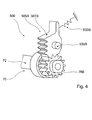
- the locking device 500 by means of which the second module 5 is supported downward in each position deviating from its rest position, has in the region of each leg element 64A, 64B a first latching device 505A or 505B, which supports the second module 5 or the roll bar 6 can be brought into operative connection with a second latching device 506A or 506B and which permits a movement of the roll bar 6 in the direction of its supporting position.
- the first latching devices 505A, 505B shown in FIGS. 2 and 3 each have latching elements 507A, 507B, which are designed as toothed profile elements and locked in place Operating state of the locking device 500 are simultaneously operatively connected to the tooth profile of the synchronization shaft 72 formed by non-rotatably mounted on the synchronization shaft gears 78A, 78B and with the locking strips 76A, 76B in the manner shown in detail in the drawing and the locking device 500.
- the tooth profile elements 507A, 507B of the first latching devices 505A, 505B are operatively connected to the gears 78A, 78B of the synchronization shaft 72 and out of engagement with the locking strips 76A, 76B so that the roll bar 6 can freely extend into its supporting position ,
- toothed profile elements 507A, 507B are in the unlocked operating state of the locking device 500, neither with the synchronization shaft 72 nor with one of the locking strips 76A and 76B operatively connected.
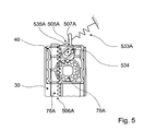
- the tooth profile elements 507A, 507B controlled out of engagement with the locking strips 76A and 76B out, wherein the tooth profile elements 507A, 507B are each firmly connected to a guide element 535A, 535B, in at least one approximately arcuate cam 534 is displaceable.
- the cam 534 is formed in a fixedly connected to the cross member 40 or with the guide elements 30 component or in itself.
- the guide elements 535A, 535B are formed in the manner shown in FIG. 5 approximately ellipsoidal.
- the tooth profile elements 507A, 507B follow the cam curves given by the cams 534 upon rotation of the synchronization shaft 72, and are brought out of engagement with the detent ledges 76A and 76B or into engagement therewith without rotation.
- the length of the control cams 534 is dimensioned such that the tooth profile elements 507A and 507B in the case of triggering the rollover protection system 11 by the gears 78A, 78B initially out of engagement with the locking strips 76A and 76B.
- the detent elements 507A and 507B are additionally disengaged from the gears 78A, 78B such that the tooth profile elements 507A and 507B do not undergo further controlled displacement and / or tilting while the gears 78A, 78B are engaged their teeth are guided past the corresponding tooth profiles of the tooth profile elements 507A and 507B under contact.
- the tooth profile elements 507A and 507B are pressed in the direction of the toothed wheels 78A, 78B by the spring devices 533A, 533B, whose force directions are preferably at least approximately parallel to the courses of the control cams 534, so that the tooth profile elements 507A and 507B contact in any case in such an operative position that they are in a force attack on the roll bar 6 in the direction of its rest position are immediately again in engagement with the gears 78A, 78B.
- FIGS. 6 and 7 show a further component group 2 for a convertible vehicle which, like the first component group 1, has a rollover protection system 11 with the associated components and a transverse stiffening structure 10 and can be connected to a hood 80 to form a preassembled structural unit.
- this component group 2 which is completed outside the vehicle, also comprises seat elements in the form of lower seatback supports 152, 154 and upper seatback locking bolts 156, 158 and headrest bearings 160, 162, each having an associated headrest 164 or 166 for a first vehicle seat 26 and a second vehicle seat 28 a row of seats, which present present rear seats.
- the seat elements which are attached to the body-mounted guides 30 of the rollover protection system 11 and to the cross member 40 of the transverse stiffening structure 10 may include in other embodiments, complete seat backs or seat bases, which optionally as part of the rollover protection system of this in the event of a crash in a the occupants thereon can be controlled in a crash-conditioning manner.
- the thus also a multifunction module performing component group 2 has in addition to the functionality of the rollover protection system 11, the through-opening 60 and seat attachment also a restraining belt system 100, which completes together with the other components of the multifunction module in its proposed compact design separately outside the vehicle and in a vehicle for final assembly can be used.
- the restraining belt system 100 is integrated into the vehicle-mounted first module 4 of the rollover protection system 11 or its guide devices 30, with a belt retractor 110, 111 of a type known per se at mid-height of the guide devices 30 is used in a roll-off body 6 in the vehicle front direction upstream profile region 35 of each formed as a hollow profile guide means 30.
- the associated seat belt 112 or 113 is guided in the profiled area 35, which is designed as a hollow profile, to an upper safety belt guide or deflection 114 or 115. From there, the safety belt 112, 113 in the vehicle forward direction extends over a backrest of a vehicle seat which is located upstream of the profile region 35 of the rollover protection system 11 and can be connected in the usual way to a seat belt buckle by a vehicle occupant.
- the illustrated restraint belt system 100 comprises two upper anchoring points 120, 122 for a child seat belt, wherein the upper anchoring points 120 and 122 are respectively secured to a side facing away from the vehicle interior 13 profile wall 46 of the cross member 40 and a tab 124th or 126, through which a strap attached to a child seat can be pulled or hooked into it.
- the upper anchoring point 120 or 122 for a child seat which is usually fixed at two attachment points in the seat area, forms a third attachment point.
- the rollover protection system 11 of the component group 2 corresponds to that of the first component group 1.
- the second component group 2 has a modified holding device 210 for the roll bar 6.
- the holding device 210 which is arranged centrally on the cross member 40, comprises a locking element 214, which is mounted pivotably about a fixed axis of rotation and which is designed to cooperate with a hook-shaped locking element counter-body 218 on the roll bar 6.
- the locking element 214 is pivotable by means of an actuator 224 out of engagement with the hook-shaped locking element counter body 218, wherein the actuator 224 is controlled in an accident situation detected by a safety sensor of the convertible vehicle by an associated control unit and in the event of a crash undergoes a change in state, which a movement of the Verrieglungselements 214 result.
- the actuator 224 is presently designed as an electromagnetic actuator of conventional design, but are also working on another principle operating actuators, such.
- piezoelectric actuators pyrotechnic actuators or equipped with a fuse insert actuators, for use in the holding device 210th
- the locking device 500 for locking the roll bar 6 in the support position is only slightly modified in the embodiment according to FIGS. 6 to 9 compared with the embodiment according to FIGS. 1 to 5, for which reason the differences will be dealt with essentially in the following description Incidentally, reference is made to the above description.
- the latching element 507A of the first latching device 505A shown in FIG. 8 and FIG. 9 substantially corresponds to the latching element 507A of the first exemplary embodiment of the rollover protection system 11 in a region arranged in the extension direction Z above the toothed wheel 78A.
- Locking element portion 507A which engages the gear wheel 78A of the synchronization device 70 in a semicircular shape and engages with a further guide element 535A_1 in a further control cam 534A 1, so that the locking element 507A with respect to the extension Z of the roll bar 6 both above and below the gear 78A controlled in and out of engagement with the detent ledge 76A into the control tracks 534A and 534A_1.
- the spring device 533A is designed as a tension spring which acts on an end of the bow-shaped region 507A_1 of the locking element 507A facing away from the gear 78A.
- the direction of force action of the spring device 533A on the latching element 507A is in this case opposite to the extension direction Z of the roll bar 6, so that the latching element 507A engages or disengages in the same manner as the latching element 507A of the first embodiment of the rollover protection system 11 in response to a rotation of the synchronization shaft 72 the engagement with the locking strip 76A is feasible and the locking device 500 in a locked or an unlocked operating state is transferred.
- the second module 5 of its support position in which the second module 5 with its roll bar 6 a seating area of one or more vehicle occupants surmounted such that the vehicle occupants in a vehicle overturn by the protection element in a conventional manner a survival space is ensured again in its rest position, in which the second module 5 is preferably lowered in relation to a backrest of a vehicle seat such that the second module 5 does not project beyond the rear seat back is lowered again, the operative connection between the locking means 505 and 506 for the deliberate lowering movement of second module 5 in the direction of its rest position, for example, by a suitable release element repealed.
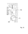
- FIG. 10 shows a modification of the locking device 500 according to the embodiment of FIG. 6 to FIG. 9, wherein a so-called double spring drive of the latching element 507A of the first latching device 505A is provided.
- the locking element 507A which is guided in response to a rotation of the synchronization shaft 72 in engagement or out of engagement with the locking strip 76A, is very compact in the embodiment of FIG. 10 and supported in the extension direction of the rollover body 6 with a double spring 536, which a Having left-hand spiraling and a right-hand spiraling for avoiding entanglement.
- the latching element 507A is connected to the toothed wheel 78A of the synchronization shaft 72 via a leaf spring 538 arranged on the circumference of the latching element 507A, wherein the catches 78A can be actuated by the toothed wheel 78A via the leaf spring 538.
- a leaf spring 538 arranged on the circumference of the latching element 507A, wherein the catches 78A can be actuated by the toothed wheel 78A via the leaf spring 538.
- the locking element 507A according to the embodiment of FIG. 10 on its side facing away from the locking strip 76A peripheral portion on a recess 539, can be easily intervened with a mounting tool through a lateral opening of a housing surrounding the locking device, whereby the locking element 507A for ease of assembly and Reversing the rollover protection system is particularly easy to engage with the locking strip 76A can be brought.
- the leaf spring is formed laterally of the locking element with tabs which extend in the direction of the gear of the synchronization shaft and this laterally border.
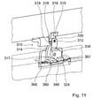
- FIGS. 11 and 12 show, in a simplified representation, the holding device 310 equipped with a fusible insert 348 for holding the rollover body 6 according to the embodiment of the rollover protection system 11 according to FIGS. 1 to 5, which however also applies to the rollover protection system according to FIG. 6 to Fig. 9 is suitable and almost identical in the embodiment of FIG. 14 ff applies.
- the holding device 310 comprises a locking element 314, which is mounted so as to be pivotable about a fixed axis of rotation 312 and has on its circumference a catch section 316, which is designed as a U-shaped recess and for interacting with it a locking element counter body 318 is designed on the roll bar 6.
- the locking element-counter body can here in a simple manner as a retaining tab below a recess on the roll bar 6 or as a bolt, a shoulder on the rollover body, or a suitable hook element, be formed.
- the locking element counter body 318 is designed as a hook element, which is fastened to a lower edge of the roll bar 6.
- the hook element 318 and the pawl section 316 of the locking element 314 are configured so that the locking element 314 can easily be brought out of engagement with the locking element counter body 318 during a rotation about its axis of rotation 312.
- the roll bar 6 is held in its lowered rest position by the engagement of the locking element 314 with the locking element counter body 318, and can be triggered by actuation of an actuator 324 by the actuator 324 at least partially rotation of the locking member 314 allows, so this disengaged with the locking element counter body 318 device.
- the locking element 314 is held in its rest position which locks the roll bar 6 by a melt insert 348 of the actuator 324 which can be melted in the event of a crash, wherein the locking element 314 is loaded radially and in tension in the rest position via the fuse link 348 is connected to a main body 338.
- the locking element 314 is formed in this embodiment lever-like manner as a kind of pivot lever.
- the main body 338 is a block element with a substantially L-shaped cross section, wherein an L-leg 339 has a holder 361 for the fuse insert 348 with a Energyzu slaughter Republic Republic Korea Republic of China, and the other L-leg 341 has a bearing 374 of the pivotable locking member 314 with its bearing pin 330 carries.
- the bearing 374 constitutes a bearing plate screwed in a manner secured against rotation with the L-leg 341 of the base body 338, which is screwed on one side of the base body 338 and is curved S-shaped against the bearing of the bolt 330 of the locking element 314, so that the Locking element 314, the bearing plate 374 and the bearing pin 330 in the axial direction of the bearing bolt 330 have an extension which substantially corresponds to the depth of the axially overlapping with this assembly body 338.
- the holding device 310 advantageously has a very small overall depth.
- the brackets 360, 361 for the fuse insert 348 are formed here as grooves, in which the present plate-shaped fuse link 348 is inserted firmly locked.
- the fuse link 348 may have a cross-sectional constriction for locking a shape adapted to the grooves holding it and for faster fusing in its middle region.
- the energy supply device 367 for generating the heat necessary for melting the fuse link 348 is expediently embodied by means of terminals connected to a current source and attached to the ends of the fuse link 348.
- the material of the fuse element can represent any material known for fuses made of metal and / or plastic.
- the biased roll bar 6 Upon melting and severing of the fuse link 348 due to the power supply, which is set by a controller in a detected crash situation, the biased roll bar 6 is released from the locking member 314 by the locking member 314 is pivoted due to the tensile load on the part of the extending roll bar 6 wherein the pawl portion 316 is disengaged from the shoulder 318.
- the reversing of the rollover protection system with a return of the extended roll bar 6 in its lowered rest position can be done in the embodiment of FIG. 11 and FIG. 12 in a simple manner by lowering the roll bar 6 in its rest position, the roll bar 6 initially on a particularly clear apparent in Fig. 12, at the upper edge of the roll bar 6 facing the lever end 315 formed in the axial direction of the bearing pin 330 of the locking element 314 extending slope 319 of the locking element 314 meets.
- the locking element 314 is at least partially formed so flexible that the downwardly moving roll bar 6 when sliding along the slope 319 with the shoulder 318 deflects the locking element 314 in the direction of arrow 375 shown in FIG. 12 or bends away, until the pawl portion 316 snaps and holds the roll bar 6.
- FIG. 13 shows, in a simplified representation, a further embodiment of a holding device 410 for holding the roll bar 6, which with respect to the locking element corresponds to the embodiment shown in particular in FIGS. 11 and 12, but can be driven pyrotechnically and, alternatively, to that shown in FIGS 11 to 12 can be used.
- the holding device 410 also comprises a locking element 414 which is mounted so as to be pivotable about a fixed axis of rotation 412 and which, like the locking element 314 of the holding device 310 shown in FIGS. 11 and 12, has a catch portion 416 at its circumference and which cooperates with a locking element counter body 418 on the roll bar 6.
- the locking element counter body 418 is also formed in this embodiment as a shoulder of a hook member which is fixed to the lower edge of the roll bar 6.
- the locking element 414 To trigger the roll bar 6, the locking element 414 must be transferred from a rest position shown in FIG. 13, in which the locking element 414 is in engagement with the locking element counter body 418, in a pivoted position in which the locking element 414 releases the rollover body 6 ,
- the locking element 414 is designed in the manner of a pivot lever, wherein a lever end 415 the latch portion 416 for engagement with the locking element counter body 418 and the other end of the lever 417 abuts a stop member 428, which is an abutment for forms the force exerted on the locking element 414 by the rollover body 6 and prevents rotation of the locking element 414.
- a support plate 434 bolted to a crossbeam 40 which abuts on one side of the support plate 434 and is guided by a tab 440 therein and at its other End carries a bearing pin 430 for the pivotable locking element 414.
- the bearing plate 474 is curved S-shaped against the bearing of the bolt 430, whereby the locking element 414, the bearing plate 474 and the bearing pin 430 in the axial direction of the bearing pin 430 have an overlap and thus require only a small overall depth.
- the actuator 424 which causes a pivoting of the locking element 414, in this case has a pyrotechnic propellant 425.
- the pyrotechnic propellant charge 425 is arranged on the side of the carrier plate 434 facing away from the stop element 428 and the bearing plate 474 such that its direction of action is essentially perpendicular to the pivoting direction of the locking element 414.
- the pyrotechnic propellant 425 drives a the carrier sheet 434 by cross-bolt, which is arranged such that it bears against it in the resting state of the locking element 414.
- the bolt In an electrical contacting of the pyrotechnic propellant 425 by means of an igniter 427 in a crash signal, the bolt is pushed by the pyrotechnic propellant 425 so far in the direction of the lower end of the lever 417 of the locking member 414 that the locking member 414 with its lower end of the lever 417 over the stop element 428 is lifted. Due to the force applied to the rollover body 6 in the extension direction, the locking element 414 is then pivoted, wherein it slides on a wedge surface 429 of the stop element 428 in the direction of the carrier plate 434.
- the reversing of the holding means 410 for holding the rollover body 6 displaced back in its rest position can be effected in that at a legislativeverlagerten bolt of the pyrotechnic propellant 425 a remindverschwenkung of the locking element 414 takes place, wherein the rollover body 6 in a shift to its rest position on one of the Upper edge of the upper end of the lever 415 of the locking member 414 formed in the axial direction of the bearing pin 430 extending slope 419 of the locking element 414 impinges.
- a certain flexibility of the locking member 414 allows upon sliding of the roll bar 6 along the slope 419 with the locking element counter body 418, a deflection of the locking member 414 in the axial direction of its bearing pin 430 until the pawl portion 416 engages and holds the roll bar 6.
- FIGS. 14 to 21 show, in a simplified representation, a further component group 3 of a convertible vehicle, in which case a rollover protection system 11 is provided in which each of the vehicle seats 26, 28 is assigned a rollover protection device 22 or 23, respectively a first module 4 fixed to the body and a second module 5 having a rollover body 24 that can be moved between a lowered rest position and an elevated supporting position, wherein the second module 5 is again guided on the first module 4 during a displacement movement.
- each rollover protection device 22, 23 has a releasable holding device 310 or 410 for holding the second module 5 with the rollover body 24 in its rest position, a locking device 600, by means of the second module 5 is automatically supported in a deviating from its rest position position against a force acting in the direction of rest force application, and a drive system 50 with a spring energy accumulator 52, by means of the second module 5 is biased in its rest position and, if necessary, in the direction of its support position displaced on.
- the rollover body 24 is designed in the manner of a rod and has in its interior an axial receiving channel 8 for the spring force accumulator 52.
- the rollover body 24 in each case represents a straight rod body, although in other embodiments optionally a curvature may also be provided in its upper region.
- the cross section of the rollover body 24 is in each case substantially round, wherein the inner cross-sectional contour in the embodiment is presently oval.
- the flats 7 and the webs 14 serve not only the stiffening, but also a rotation of the rollover body 24 and are part of the respective locking device 600 of the rollover body 24.
- the hollow profile 30 serving as a guiding device of the rollover body 6 is arranged with its lower edge opposite the foot element 34 of the first module 4 at a distance, wherein the tube profile 30 in rest position of the roll bar 6 and the rollover body 24, which is shown in Fig. 21, an upper end portion of the rollover body 6 and 24 surrounds and in Supporting position of the rollover body 6 and 24, which is shown in Fig. 13 on the left based on the rollover protection device 23, the lower end portion of the rollover body 6 and 24 receives.
- connection of the tube profile 30 with the foot member 34 of the body-mounted module 4 is carried out in the embodiments shown in each case via a connecting profile 38, which is introduced on the side facing the vehicle side of the tube profile 30 in a correspondingly shaped profile section 30 and screwed hereby.
- the connecting profile 38 as the other profiles of the rollover protection system 11 is designed as an extruded profile, wherein in the present case for the connection profile 38, a U-section is selected.
- any other profile shape of an open or closed profile for the connection profile can be chosen according to the present application, wherein the choice of geometry with regard to a slender construction as possible of the rollover protection system 11 is made.
- the rollover protection devices 22, 23 of two vehicle seats of a seat row are arranged respectively in the opposite direction substantially off-center to the assigned vehicle seat, so that there is sufficient space between the rollover protection devices 22, 23 for a generous through-loading opening 60 is given, by means of bulky goods from a rear-side receiving space or trunk 12 can be performed in the vehicle interior 11.
- the rollover protection devices 22, 23 are also here in each case with a not shown in the usual way and executed crash sensor system of the vehicle, in which case the holding device 310 or 410 is driven, by means of which the respective rollover body 24 is held against the force of the spring force accumulator 52 in rest position.
- the respective holding device 310, 410 releases the rollover body 24, so that the rollover body 24 is displaced by the force of the spring force memory 52 in its extended upper support position in which it is secured by the locking device 600 against re-entry.
- the rollover body 24 at its upper end in each case a baffle profile 16 with an opposite of the cross-sectional area of the rollover body 24 enlarged baffle 17.
- This impact profile which prevents a boring of the bar-like rollover body in the respective given background in a vehicle rollover, is present, as shown in particular in Fig. 18, as a hollow profile with a plurality of cavities formed on its surface facing away from the body floor or baffle a Curvature has.
- On the sides of the impact profile 19 is closed with panels 20.
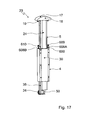
- FIGS. 17 and 18 show in more detail the embodiment of the rollover protection device 23 which, with an identical embodiment of the corresponding rollover protection device 22, is part of the component group 3 shown in FIGS. 14 ff.
- the drive system is modified in the embodiment according to FIG. 14 et seq.
- the spring energy accumulator 52 is here - in contrast to the drive system 50 shown in Fig. 2 with a compression spring - as a tension spring formed, which is guided in a receiving channel 8 of the rollover body 24 on a spring guide rod 53.
- a spring suspension 55 is formed at its upper end and slidably mounted on a central region a spring plate 56, wherein the tension spring 52 between the spring suspension 55 and the voltage applied to a stop of the rollover body 24 spring plate 56 in rest position of the rollover body 24 to train is biased.
- Fig. 14 ff differs from the previously described embodiments with respect to the locking device 600 used for automatically locking the extended rollover body 24 in its supporting position.
- the locking device 600 has at least one first latching device 605 fixedly connected to the first module 4, which can be brought into operative connection with a second latching device 606 fixedly connected to the second module 5 for supporting the second module 5 and which effects a movement of the second latching device 606 second module 5, starting from its rest position in the direction of its supporting position permits.
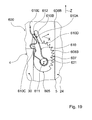
- the first latching device 605 of the locking device 600 includes in the embodiment shown in Fig. 14 ff two in the direction of their operative position acted upon by a force, rotatably mounted body-mounted and each with a tooth profile 607 designed locking body 608A, 608B.
- Each blocking body 608A, 608B is assigned in each case a spring device 609, 610 via which the blocking bodies 608A, 608B are each sprung in the direction of the operative position of the first latching device 605 in such a manner that the blocking bodies 608A, 608B about bearing pins from the position shown in FIG are pivoted in each case in a direction of rotation represented by an arrow X in Fig. 19.
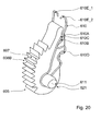
- the bearing bolts 611 are supported on the module 4 which is fixed to the body, the locking bodies 608A and 608B being fixed in the axial extension of the bearing bolts 611 via the spring devices 609 and 610 in the manner shown in more detail in FIGS. 19 and 20 via the spring devices 609 and 610 thus clearly positioned.
- the spring devices 609 and 610 engage around the bearing bolts 611 on both sides of the disk-like locking bodies 608A and 608B.
- the spring means 609 and 610 are biased in the wrap region of the bearing pins 611 in the installation position to adjust the frictional force between the spring means 609 and 610 and the bearing pin 611 to such a value that the locking bodies 608A and 608B are not slidable on the bearing pin 611.
- the second latching device 606 is formed by a respective surface 606B of the second module 5 or rollover body 6, which faces a blocking body 608A or 608B and is movable relative to the respectively corresponding blocking body 608A or 608B, with the respective tooth profile 607 of a blocking body 608A or 608B is in frictional engagement in operative position of the first latching device 605 such that a movement of the second module 5 is prevented from a position deviating from the rest position in the direction of its rest position.
- the spring devices 609 and 610 respectively associated with the blocking bodies 608A and 608B are each formed with blocking devices 609A, 610A, wherein the blocking bodies can be held in a position equivalent to a deactivated state of the first locking device 605 when the blocking device 610A is activated.
- the bow-wire springs 609 and 610 are each provided with a first bow portion 610B, which is operable to activate the locking means 610A with a second bow portion 610C in the manner shown in FIG. 20 in operative connection such that the locking bodies 608A and 6B8B in the the deactivated state of the first latch 605 equivalent positions in which a relative movement between the first module 4 and the second module 5 is not prevented by the locking device 600, are held.
- the stirrup wire springs 609 and 610 are each inserted with a first leg 610D, which is substantially U-shaped, into slot-like recesses 612 of the locking bodies 608A and 608B and abut with their second leg 610E on the body-mounted module 4 in such a way the spring means 609 and 610 are in a biasing position. Due to this bias, the blocking bodies 608A and 608B can be pivoted about the bearing pins 611 in the deactivated state of the locking devices 609A, 610A in their positions corresponding to the locking state of the first latching device 605.
- the first stirrup portions 610B of the stirrup wire springs each face the central portion, i. H. the U-traverse, the stirrup wire springs, which is inserted into the slot-like recess 612 of the locking body, subsequent areas in which the first leg 610D of the stirrup wire springs is designed with a larger width than the second stirrup areas 610C at congruent areas of the second, with two open straps trained thigh 610E.
- the legs 610D and 610E of the spring devices 609 and 610 thus form the locking devices 610A in such a way that, when the locking devices 610A are activated, they intersect in the region of the hoop areas 610B and 610C, hold each other and can not spread apart due to the internal prestressing, as shown in FIG Fig. 20 can be seen.
- the stirrup wire springs 609 and 610 are designed in the region of their free ends with the stirrup ends 610E_1 and 610E_2 which are designed to be displaceable relative to one another in the manner illustrated in more detail in FIG. That is, the locking means 610A are each deactivatable or activatable by increasing the distance of the stirrup wire ends of the spring means 609 and 610 such that the leg arms of the spring means 609 and 610 can be brought past each other in the region of the stirrup portions 610B and 610C.
- the locking bodies 608A and 608B are then either held in the non-locking position by the locking means 610A or released to adjust the operative position of the first locking means 605.
- the locking body 608B When the locking device 610A of the spring device 610 associated with the locking body 608B in FIG. 18 is deactivated, the locking body 608B is pivoted about the bearing pin 611 by the spring device 610 into a position corresponding to the active state of the first locking device 605. Although in this position of the blocking body 608B an extension movement of the second module 5 in the direction of its supporting position by the first latching device 605 is permitted, however, a movement of the second module 5 in the direction of its rest position by an operative connection between the tooth profile 607 of the locking body 608B and the second Locking device 606 effectively prevented.
- the biasing force of the spring means 609 and 610 in the direction of the operative positions of the locking body 608A and 608B is presently provided such that an abutment of the locking body 608A and 608B on the present as the surface of the rollover body 24 locking device 606 does not hinder an extension movement.
- the locking elements 608A and 608B that represent the tooth-cam pivot about the bearing pin 611A counter to the direction of rotation X and thus do not build up a locking action between the two latching devices 605 and 606.
- the blocking body 608B When the blocking body 608B is pivoted into its operative position, the blocking body 608B, with its tooth profile 607 facing the latching surface 606B, at least partially penetrates the latching surface 606B of the latching device 606, whereby between the blocking body 608B and the rollover body 24 is a positive connection and the rollover body 24 is held securely against a retraction in the direction of its rest position.
- the tooth geometry of the tooth profile 607 is embodied with pointed teeth having knife-like ends and the material for the tooth profile 607 harder with respect to the material of the surface of the rollover body 24 in order to reliably lock the rollover body 24 guarantee.
- an optionally elastic deformability of the tooth profile may alternatively be provided for this purpose.
- the rollover body 24 is formed on the underside of its impact profile 16 with wedge surfaces 18 having, in this case designed truncated pyramid unlocking elements 19, by means of which the locking body 608A, 608B are brought into the rest position in engagement with the second locking device 606 after a retraction of the rollover body.
- the blocking bodies 608A, 608B are withdrawn, with the widened bow portions 610B of the spring means 609 and 610 catching behind the free bow portions 610C and thus canceling out the effect of the bow wire springs 609, 610.
- the rollover body 24 can thus be lowered to its starting position.
- the free spring ends 610E_1, 610E_2 are pressed apart via the aforementioned unlocking elements 19 of the rollover body 24, so that the spring devices 609 and 610, the tooth cam or locking body 608A, 608B again to the latching surface 606B of the rollover body 24 for conditioning.
- the latching surfaces 606B in the present case are formed with a knurling or with a profile that increases the coefficient of friction of the latching surfaces.
- the locking bodies are each mounted on the body-first module, but also a reverse arrangement may be provided with a storage on the extendable module and a frictional engagement on a body-mounted surface.
- the transverse stiffening structure 10 with the through-loading 60 is essentially formed by the cross member 40.
- the ends of the cross member 40 in this embodiment are each formed with an undercut 41 having profile 42, which corresponds in terms of its shape with a profile 44 of the pipe section 30 of the body-first module 4.
- the cross member 40 thus forms a preassemblable unit with the rollover protection devices 22, 23, which can be screwed through lateral holes 48 to the vehicle body.
- the vehicle-mounted first module 4 of the respective rollover protection device 22, 23 is likewise each formed with an integrated restraining belt system 100, wherein at the middle height of the tubular profile 30 a belt retractor 110 moves into a rollover body 24 in the vehicle front direction upstream profile region 35 of the vehicle-fixed pipe profile 30 is inserted. From this belt retractor 110, the safety belt 112 is guided in the profiled area 35 designed as a hollow profile to an upper safety belt guide or deflection 114 and from there into the passenger compartment 11.
- the restraint belt system 100 includes two upper anchorage points 120, 122 for a child seat belt, one associated with each of the upper anchor points 120, 122, respectively, of a rollover protection device 22, 23.
- the component group 3 according to FIG. 14 ff furthermore has seating elements, wherein the rollover protection devices 22, 23 each have a seat connection device in the form of lower seat back bearings 152, 154 and upper seat back locking bolts 156, 158 for a first vehicle seat 26 and a second vehicle seat 28 Row of seats, which present present rear seats on.
- FIGS. 22 and 23 show design measures for preventing rattling noises of the rollover body 24 in the guide device 30 embodied as a tubular profile in the lowered standby position of the rollover body 24. Although these structural measures are described herein in connection with the component group 3, these can of course be used also with the component groups 1 and 2 application find.
- the guide device can be formed on its inner wall facing the rollover body 24 with a projecting web 31 extending in the extension direction of the rollover body 24, which is resiliently held by a rollover body 24 in a corresponding peripheral location Centering element 32 is encompassed.
- the clip-like centering element 32 is inserted into a peripheral recess 33 on the rollover body 24, wherein the arrangement of the centering element 32 takes place at an upper end of the rollover body 24 below the impact profile 16.
- the wall 36 A form a four-sided spring guide.
- FIG. 23 A constructive measure for centering the rollover body 24 in its lower abutment region is shown in Fig. 23, it being understood that about a foot of the spring guide rod 53 is a centering crown 37 is provided with spring-like projecting material lugs 37A at the periphery, wherein the resilient material lugs 37A rest in the resting state of the rollover body 24 on the spring guide webs 36 and thus ensure a rattle-free storage of the rollover body 24 at its lower end in the rest position.
- the height stop 43 is formed as a U-shaped stop element, which is arranged in the region of an opening 39 through the wall of the tubular profile 30 and engage around the wall thickness of the tubular profile 30 in the extension direction of the rollover body 24 on the wall of the side profile 30 with the U-legs.
- a screw 44 takes place a jamming of the height stop 43 with the wall of the pipe profile 30th
- the rollover body 24 may be designed to stop at the height stop 43 in a simple manner also with a recess 25.
- FIG. 25 shows an advantageous joining connection between a profile-like lateral guide device 30 and a cross member 40 connected thereto, which extends in the vehicle transverse direction, as shown for example in FIGS. 14 and 15.
- the transverse profile 40 is formed as a hollow profile with a plurality of cavities and a central web 45, wherein in the region of a connecting surface with the adjacent lateral guide means 30, a centering nose 47 is provided, which engages in a corresponding recess 59 of the guide means 30.
- the recess 33 described with reference to FIG. 22 can serve for receiving the centering element 32.
- lateral supports 30A, 30B designed by milling are provided on the guide device 30 for simpler joining connection between the guide device 30 and the transverse profile 40, which laterally surround the transverse profile 40.
- the third component group 3 can be connected according to Fig. 14 ff with a hood to an externally pre-assembled multifunction module.
Landscapes
- Engineering & Computer Science (AREA)
- Mechanical Engineering (AREA)
- Seats For Vehicles (AREA)
- Air Bags (AREA)
- Body Structure For Vehicles (AREA)
Applications Claiming Priority (1)
| Application Number | Priority Date | Filing Date | Title |
|---|---|---|---|
| DE102005028929A DE102005028929B4 (de) | 2005-06-22 | 2005-06-22 | Bauteilgruppe für ein Cabriolet-Kraftfahrzeug |
Publications (3)
| Publication Number | Publication Date |
|---|---|
| EP1736376A2 true EP1736376A2 (fr) | 2006-12-27 |
| EP1736376A3 EP1736376A3 (fr) | 2008-07-30 |
| EP1736376B1 EP1736376B1 (fr) | 2016-01-06 |
Family
ID=36992658
Family Applications (1)
| Application Number | Title | Priority Date | Filing Date |
|---|---|---|---|
| EP06012907.9A Expired - Lifetime EP1736376B1 (fr) | 2005-06-22 | 2006-06-22 | Module pré assemblé pour un véhicule cabriolet |
Country Status (3)
| Country | Link |
|---|---|
| US (1) | US7540535B2 (fr) |
| EP (1) | EP1736376B1 (fr) |
| DE (2) | DE102005028929B4 (fr) |
Cited By (3)
| Publication number | Priority date | Publication date | Assignee | Title |
|---|---|---|---|---|
| DE102007042882A1 (de) * | 2007-09-08 | 2009-03-12 | Wilhelm Karmann Gmbh | Führungselement zur Führung zweier relativ zueinander bewegbarer Bauelemente, insbesondere einer Überrollschutzeinrichtung eines Cabriolet-Fahrzeugs |
| DE102007054254A1 (de) * | 2007-11-14 | 2009-05-28 | Ise Automotive Gmbh | Überrollschutzsystem für Kraftfahrzeuge |
| WO2010149659A1 (fr) * | 2009-06-25 | 2010-12-29 | Bayerische Motoren Werke Aktiengesellschaft | Système de protection contre les tonneaux |
Families Citing this family (15)
| Publication number | Priority date | Publication date | Assignee | Title |
|---|---|---|---|---|
| DE10318594B4 (de) * | 2003-04-24 | 2008-01-03 | Wilhelm Karmann Gmbh | Überrollschutz-Vorrichtung für ein Kraftfahrzeug |
| DE102004035015B3 (de) * | 2004-07-20 | 2005-12-08 | Ise Innomotive Systems Europe Gmbh | Überrollschutzsystem für Kraftfahrzeuge mit versenkbarem Dach |
| DE102006041261A1 (de) * | 2006-09-02 | 2008-03-06 | Wilhelm Karmann Gmbh | Überrollschutzsystem für ein Cabriolet-Fahrzeug |
| DE102006042284A1 (de) * | 2006-09-08 | 2008-03-27 | Dr.Ing.H.C. F. Porsche Ag | Kraftfahrzeug mit einer Überrollbügelanordnung |
| DE102006059578A1 (de) * | 2006-12-16 | 2008-06-19 | Wilhelm Karmann Gmbh | Überrollschutzsystem für ein Kraftfahrzeug, insbesondere für ein Cabriolet-Fahrzeug |
| DE102007015324B4 (de) | 2007-03-30 | 2011-07-07 | Wilhelm Karmann GmbH, 49084 | Verbindung eines Fahrzeugquermoduls mit einer Karosserie eines Kraftfahrzeugs, insbesondere eines Cabriolet-Fahrzeugs |
| JP2008272270A (ja) * | 2007-04-28 | 2008-11-13 | Bizen Hatsujo Kk | 車両用ヘッドレスト |
| DE102007046535A1 (de) * | 2007-09-28 | 2009-04-02 | Dr. Ing. H.C. F. Porsche Aktiengesellschaft | Kraftfahrzeug, insbesondere Cabriolet, mit einer hinter den Sitzen angeordneten Überrollschutzvorrichtung |
| DE102007046536A1 (de) | 2007-09-28 | 2009-04-02 | Dr. Ing. H.C. F. Porsche Aktiengesellschaft | Überrollschutzeinrichtung |
| US20090278342A1 (en) * | 2008-05-06 | 2009-11-12 | Gm Global Technology Operations, Inc. | Vehicle roll bar apparatus with active material actuation |
| DE102008043443A1 (de) * | 2008-11-04 | 2010-05-20 | Ise Automotive Gmbh | Überrollschutzsystem mit verbesserter Haltevorrichtung |
| KR101371458B1 (ko) | 2012-07-16 | 2014-03-10 | 현대자동차주식회사 | 오픈카의 배플구조 |
| US8955880B2 (en) * | 2013-03-11 | 2015-02-17 | Oshkosh Corporation | Carrier adjustable headboard |
| WO2017177174A1 (fr) | 2016-04-08 | 2017-10-12 | Oshkosh Corporation | Système de mise à niveau pour dispositif de levage |
| DE102022103930A1 (de) * | 2022-02-18 | 2023-08-24 | Bayerische Motoren Werke Aktiengesellschaft | Fahrzeug, insbesondere Cabriolet |
Citations (6)
| Publication number | Priority date | Publication date | Assignee | Title |
|---|---|---|---|---|
| DE9304820U1 (de) | 1993-03-30 | 1994-01-13 | Hoffmann, Gerhard, 85630 Grasbrunn | Kraftfahrzeug-Cabrio |
| DE19642821A1 (de) | 1995-12-14 | 1997-06-19 | Porsche Ag | Verfahren zum Herstellen einer Aufbaustruktur für ein Fahrzeug, insbesondere Cabriolet |
| DE19838989C1 (de) | 1998-08-27 | 1999-11-11 | Ise Gmbh | Überroll-Schutzvorrichtung |
| EP1084914A2 (fr) | 1999-09-13 | 2001-03-21 | Wilhelm Karmann GmbH | Module préassemblé pour un véhicule cabriolet |
| DE102004016362A1 (de) | 2003-04-10 | 2004-10-28 | Bayerische Motoren Werke Ag | Baueinheit für ein Cabriolet |
| DE10318594A1 (de) | 2003-04-24 | 2004-11-25 | Wilhelm Karmann Gmbh | Überrollschutz-Vorrichtung für ein Kraftfahrzeug |
Family Cites Families (12)
| Publication number | Priority date | Publication date | Assignee | Title |
|---|---|---|---|---|
| DE3922509A1 (de) * | 1989-07-08 | 1991-01-17 | Daimler Benz Ag | Kopfstuetze fuer ruecksitze |
| DE19905578A1 (de) * | 1999-02-11 | 2000-08-17 | Bayerische Motoren Werke Ag | Cabriolet mit Verdeck und Überrollbügel |
| DE19906912C1 (de) * | 1999-02-19 | 2000-04-13 | Ise Gmbh | Überroll-Schutzsystem für Kraftfahrzeuge |
| DE19949960C2 (de) * | 1999-10-16 | 2002-06-13 | Cts Fahrzeug Dachsysteme Gmbh | Fahrzeugdach mit einem zwischen Schließstellung und Öffnungsstellung verstellbaren Verdeck |
| US6491346B1 (en) * | 2000-06-01 | 2002-12-10 | Dow Global Technologies, Inc. | Seating system and method for making the same |
| DE10044930C1 (de) * | 2000-09-12 | 2002-03-28 | Ise Gmbh | Überrollschutzsystem für Kraftfahrzeuge |
| DE10219447B4 (de) * | 2002-05-02 | 2005-10-20 | Ise Gmbh | Überrollschutzsystem für Kraftfahrzeuge mit einer selbsthaltenden Entriegelungseinrichtung |
| DE10316346B4 (de) * | 2003-04-10 | 2016-12-29 | Bayerische Motoren Werke Aktiengesellschaft | Überroll-Schutzsystem für ein Cabriolet |
| US7341278B2 (en) * | 2004-06-21 | 2008-03-11 | Heuliez | Safety device used in case a vehicle rolls over |
| US20060001248A1 (en) * | 2004-07-02 | 2006-01-05 | Gerard Queveau | Safety device used in case a vehicle rolls over |
| DE102005029253B4 (de) * | 2005-06-23 | 2009-04-02 | Wilhelm Karmann Gmbh | Cabriolet mit einem Überrollschutzsystem |
| DE102006006659B3 (de) * | 2006-02-14 | 2007-06-21 | Automotive Group Ise Innomotive Systems Europe Gmbh | Überrollschutzsystem für Kraftfahrzeuge mit einem annähernd fahrzeugbreiten aktiv aufstellbaren Überrollbügel |
-
2005
- 2005-06-22 DE DE102005028929A patent/DE102005028929B4/de not_active Expired - Fee Related
-
2006
- 2006-06-22 DE DE202006020774U patent/DE202006020774U1/de not_active Expired - Lifetime
- 2006-06-22 US US11/425,902 patent/US7540535B2/en not_active Expired - Fee Related
- 2006-06-22 EP EP06012907.9A patent/EP1736376B1/fr not_active Expired - Lifetime
Patent Citations (6)
| Publication number | Priority date | Publication date | Assignee | Title |
|---|---|---|---|---|
| DE9304820U1 (de) | 1993-03-30 | 1994-01-13 | Hoffmann, Gerhard, 85630 Grasbrunn | Kraftfahrzeug-Cabrio |
| DE19642821A1 (de) | 1995-12-14 | 1997-06-19 | Porsche Ag | Verfahren zum Herstellen einer Aufbaustruktur für ein Fahrzeug, insbesondere Cabriolet |
| DE19838989C1 (de) | 1998-08-27 | 1999-11-11 | Ise Gmbh | Überroll-Schutzvorrichtung |
| EP1084914A2 (fr) | 1999-09-13 | 2001-03-21 | Wilhelm Karmann GmbH | Module préassemblé pour un véhicule cabriolet |
| DE102004016362A1 (de) | 2003-04-10 | 2004-10-28 | Bayerische Motoren Werke Ag | Baueinheit für ein Cabriolet |
| DE10318594A1 (de) | 2003-04-24 | 2004-11-25 | Wilhelm Karmann Gmbh | Überrollschutz-Vorrichtung für ein Kraftfahrzeug |
Cited By (5)
| Publication number | Priority date | Publication date | Assignee | Title |
|---|---|---|---|---|
| DE102007042882A1 (de) * | 2007-09-08 | 2009-03-12 | Wilhelm Karmann Gmbh | Führungselement zur Führung zweier relativ zueinander bewegbarer Bauelemente, insbesondere einer Überrollschutzeinrichtung eines Cabriolet-Fahrzeugs |
| DE102007054254A1 (de) * | 2007-11-14 | 2009-05-28 | Ise Automotive Gmbh | Überrollschutzsystem für Kraftfahrzeuge |
| DE102007054254B4 (de) * | 2007-11-14 | 2012-04-12 | Ise Automotive Gmbh | Überrollschutzsystem für Kraftfahrzeuge |
| WO2010149659A1 (fr) * | 2009-06-25 | 2010-12-29 | Bayerische Motoren Werke Aktiengesellschaft | Système de protection contre les tonneaux |
| DE102009030408A1 (de) | 2009-06-25 | 2010-12-30 | Bayerische Motoren Werke Aktiengesellschaft | Überrollschutzsystem |
Also Published As
| Publication number | Publication date |
|---|---|
| US7540535B2 (en) | 2009-06-02 |
| DE102005028929A1 (de) | 2006-12-28 |
| EP1736376B1 (fr) | 2016-01-06 |
| EP1736376A3 (fr) | 2008-07-30 |
| US20060290125A1 (en) | 2006-12-28 |
| DE202006020774U1 (de) | 2010-02-04 |
| DE102005028929B4 (de) | 2009-04-09 |
Similar Documents
| Publication | Publication Date | Title |
|---|---|---|
| EP1736376B1 (fr) | Module pré assemblé pour un véhicule cabriolet | |
| EP0709248B1 (fr) | Siège de véhicule automobile à dossier rabattable vers l'avant | |
| EP2006164A2 (fr) | Système de protection contre les tonneaux pour véhicules automobiles dotés d'au moins un arceau de sécurité pyrotechnique pouvant être monté activement | |
| EP1620291B1 (fr) | Structure de protection pour vehicule automobile | |
| EP1736373B1 (fr) | Système de protection pour le capotage d'un véhicule automobile | |
| DE102007017998A1 (de) | Schutzvorrichtungsanordnung für einen Sitz eines Kraftfahrzeuges | |
| DE19750693C2 (de) | Ausfahrbarer Überrollbügel für Kraftfahrzeuge | |
| DE10316346B4 (de) | Überroll-Schutzsystem für ein Cabriolet | |
| EP3727929B1 (fr) | Unité de blocage en cas de collisions, en particulier pour un siège de véhicule, et siège de véhicule | |
| DE102006028664B4 (de) | Überrollschutzsystem für ein Kraftfahrzeug | |
| DE19925520C1 (de) | Überroll-Schutzsystem für Kraftfahrzeuge | |
| EP1736371B1 (fr) | Véhicule avec système de protection en cas de retournement | |
| EP1955908B1 (fr) | Système de protection en cas de tonneaux pour véhicules automobiles comprenant un arceau orientable dirigé par capteur pouvant être placé activement | |
| DE102006006659B3 (de) | Überrollschutzsystem für Kraftfahrzeuge mit einem annähernd fahrzeugbreiten aktiv aufstellbaren Überrollbügel | |
| EP1547873B1 (fr) | système d'arceau de sécurité pour véhicule avec arceau déployable | |
| DE102005028966B4 (de) | Kraftfahrzeug mit einem Überrollschutzsystem an einer Fahrzeugquerwand | |
| DE102005028879B4 (de) | Überrollschutzsystem für ein Kraftfahrzeug | |
| EP1493635B1 (fr) | Arceau de sécurité pour cabiolet | |
| EP1736374B1 (fr) | Système d'arceau de sécurité pour un véhicule à moteur | |
| DE102006000909B4 (de) | Überrollschutzsystem für ein Cabriolet-Fahrzeug mit gekrümmtem Überrollkörper | |
| DE102006041261A1 (de) | Überrollschutzsystem für ein Cabriolet-Fahrzeug | |
| DE102006002476B4 (de) | Überrollschutzsystem für ein Kraftfahrzeug | |
| DE10103249C1 (de) | Überrollschutzsystem für Kraftfahrzeuge | |
| EP1955907B1 (fr) | Système de protection avec arceau de sécurité pour des véhicules automobiles | |
| EP1514740B1 (fr) | Dispositif d'arceau de sécurité pour véhicules avec un arceau déployable |
Legal Events
| Date | Code | Title | Description |
|---|---|---|---|
| PUAI | Public reference made under article 153(3) epc to a published international application that has entered the european phase |
Free format text: ORIGINAL CODE: 0009012 |
|
| AK | Designated contracting states |
Kind code of ref document: A2 Designated state(s): AT BE BG CH CY CZ DE DK EE ES FI FR GB GR HU IE IS IT LI LT LU LV MC NL PL PT RO SE SI SK TR |
|
| AX | Request for extension of the european patent |
Extension state: AL BA HR MK YU |
|
| PUAL | Search report despatched |
Free format text: ORIGINAL CODE: 0009013 |
|
| AK | Designated contracting states |
Kind code of ref document: A3 Designated state(s): AT BE BG CH CY CZ DE DK EE ES FI FR GB GR HU IE IS IT LI LT LU LV MC NL PL PT RO SE SI SK TR |
|
| AX | Request for extension of the european patent |
Extension state: AL BA HR MK RS |
|
| 17P | Request for examination filed |
Effective date: 20080813 |
|
| 17Q | First examination report despatched |
Effective date: 20081027 |
|
| AKX | Designation fees paid |
Designated state(s): AT BE BG CH CY CZ DE DK EE ES FI FR GB GR HU IE IS IT LI LT LU LV MC NL PL PT RO SE SI SK TR |
|
| 19U | Interruption of proceedings before grant |
Effective date: 20090629 |
|
| 19W | Proceedings resumed before grant after interruption of proceedings |
Effective date: 20101201 |
|
| RAP1 | Party data changed (applicant data changed or rights of an application transferred) |
Owner name: VALMET AUTOMOTIVE OY |
|
| GRAP | Despatch of communication of intention to grant a patent |
Free format text: ORIGINAL CODE: EPIDOSNIGR1 |
|
| INTG | Intention to grant announced |
Effective date: 20141205 |
|
| GRAS | Grant fee paid |
Free format text: ORIGINAL CODE: EPIDOSNIGR3 |
|
| GRAP | Despatch of communication of intention to grant a patent |
Free format text: ORIGINAL CODE: EPIDOSNIGR1 |
|
| INTG | Intention to grant announced |
Effective date: 20150421 |
|
| GRAA | (expected) grant |
Free format text: ORIGINAL CODE: 0009210 |
|
| AK | Designated contracting states |
Kind code of ref document: B1 Designated state(s): AT BE BG CH CY CZ DE DK EE ES FI FR GB GR HU IE IS IT LI LT LU LV MC NL PL PT RO SE SI SK TR |
|
| REG | Reference to a national code |
Ref country code: GB Ref legal event code: FG4D Free format text: NOT ENGLISH |
|
| REG | Reference to a national code |
Ref country code: CH Ref legal event code: EP |
|
| REG | Reference to a national code |
Ref country code: IE Ref legal event code: FG4D Free format text: LANGUAGE OF EP DOCUMENT: GERMAN |
|
| REG | Reference to a national code |
Ref country code: AT Ref legal event code: REF Ref document number: 768574 Country of ref document: AT Kind code of ref document: T Effective date: 20160215 |
|
| REG | Reference to a national code |
Ref country code: DE Ref legal event code: R096 Ref document number: 502006014700 Country of ref document: DE |
|
| REG | Reference to a national code |
Ref country code: LT Ref legal event code: MG4D |
|
| REG | Reference to a national code |
Ref country code: NL Ref legal event code: MP Effective date: 20160106 |
|
| PG25 | Lapsed in a contracting state [announced via postgrant information from national office to epo] |
Ref country code: NL Free format text: LAPSE BECAUSE OF FAILURE TO SUBMIT A TRANSLATION OF THE DESCRIPTION OR TO PAY THE FEE WITHIN THE PRESCRIBED TIME-LIMIT Effective date: 20160106 |
|
| PG25 | Lapsed in a contracting state [announced via postgrant information from national office to epo] |
Ref country code: GR Free format text: LAPSE BECAUSE OF FAILURE TO SUBMIT A TRANSLATION OF THE DESCRIPTION OR TO PAY THE FEE WITHIN THE PRESCRIBED TIME-LIMIT Effective date: 20160407 Ref country code: ES Free format text: LAPSE BECAUSE OF FAILURE TO SUBMIT A TRANSLATION OF THE DESCRIPTION OR TO PAY THE FEE WITHIN THE PRESCRIBED TIME-LIMIT Effective date: 20160106 Ref country code: FI Free format text: LAPSE BECAUSE OF FAILURE TO SUBMIT A TRANSLATION OF THE DESCRIPTION OR TO PAY THE FEE WITHIN THE PRESCRIBED TIME-LIMIT Effective date: 20160106 Ref country code: IT Free format text: LAPSE BECAUSE OF FAILURE TO SUBMIT A TRANSLATION OF THE DESCRIPTION OR TO PAY THE FEE WITHIN THE PRESCRIBED TIME-LIMIT Effective date: 20160106 |
|
| PG25 | Lapsed in a contracting state [announced via postgrant information from national office to epo] |
Ref country code: PL Free format text: LAPSE BECAUSE OF FAILURE TO SUBMIT A TRANSLATION OF THE DESCRIPTION OR TO PAY THE FEE WITHIN THE PRESCRIBED TIME-LIMIT Effective date: 20160106 Ref country code: SE Free format text: LAPSE BECAUSE OF FAILURE TO SUBMIT A TRANSLATION OF THE DESCRIPTION OR TO PAY THE FEE WITHIN THE PRESCRIBED TIME-LIMIT Effective date: 20160106 Ref country code: LT Free format text: LAPSE BECAUSE OF FAILURE TO SUBMIT A TRANSLATION OF THE DESCRIPTION OR TO PAY THE FEE WITHIN THE PRESCRIBED TIME-LIMIT Effective date: 20160106 Ref country code: PT Free format text: LAPSE BECAUSE OF FAILURE TO SUBMIT A TRANSLATION OF THE DESCRIPTION OR TO PAY THE FEE WITHIN THE PRESCRIBED TIME-LIMIT Effective date: 20160506 Ref country code: LV Free format text: LAPSE BECAUSE OF FAILURE TO SUBMIT A TRANSLATION OF THE DESCRIPTION OR TO PAY THE FEE WITHIN THE PRESCRIBED TIME-LIMIT Effective date: 20160106 Ref country code: IS Free format text: LAPSE BECAUSE OF FAILURE TO SUBMIT A TRANSLATION OF THE DESCRIPTION OR TO PAY THE FEE WITHIN THE PRESCRIBED TIME-LIMIT Effective date: 20160506 |
|
| REG | Reference to a national code |
Ref country code: DE Ref legal event code: R097 Ref document number: 502006014700 Country of ref document: DE |
|
| PG25 | Lapsed in a contracting state [announced via postgrant information from national office to epo] |
Ref country code: DK Free format text: LAPSE BECAUSE OF FAILURE TO SUBMIT A TRANSLATION OF THE DESCRIPTION OR TO PAY THE FEE WITHIN THE PRESCRIBED TIME-LIMIT Effective date: 20160106 Ref country code: EE Free format text: LAPSE BECAUSE OF FAILURE TO SUBMIT A TRANSLATION OF THE DESCRIPTION OR TO PAY THE FEE WITHIN THE PRESCRIBED TIME-LIMIT Effective date: 20160106 |
|
| PLBE | No opposition filed within time limit |
Free format text: ORIGINAL CODE: 0009261 |
|
| STAA | Information on the status of an ep patent application or granted ep patent |
Free format text: STATUS: NO OPPOSITION FILED WITHIN TIME LIMIT |
|
| PG25 | Lapsed in a contracting state [announced via postgrant information from national office to epo] |
Ref country code: RO Free format text: LAPSE BECAUSE OF FAILURE TO SUBMIT A TRANSLATION OF THE DESCRIPTION OR TO PAY THE FEE WITHIN THE PRESCRIBED TIME-LIMIT Effective date: 20160106 Ref country code: CZ Free format text: LAPSE BECAUSE OF FAILURE TO SUBMIT A TRANSLATION OF THE DESCRIPTION OR TO PAY THE FEE WITHIN THE PRESCRIBED TIME-LIMIT Effective date: 20160106 Ref country code: SK Free format text: LAPSE BECAUSE OF FAILURE TO SUBMIT A TRANSLATION OF THE DESCRIPTION OR TO PAY THE FEE WITHIN THE PRESCRIBED TIME-LIMIT Effective date: 20160106 |
|
| 26N | No opposition filed |
Effective date: 20161007 |
|
| PG25 | Lapsed in a contracting state [announced via postgrant information from national office to epo] |
Ref country code: BE Free format text: LAPSE BECAUSE OF NON-PAYMENT OF DUE FEES Effective date: 20160630 |
|
| REG | Reference to a national code |
Ref country code: DE Ref legal event code: R119 Ref document number: 502006014700 Country of ref document: DE |
|
| PG25 | Lapsed in a contracting state [announced via postgrant information from national office to epo] |
Ref country code: MC Free format text: LAPSE BECAUSE OF FAILURE TO SUBMIT A TRANSLATION OF THE DESCRIPTION OR TO PAY THE FEE WITHIN THE PRESCRIBED TIME-LIMIT Effective date: 20160106 |
|
| REG | Reference to a national code |
Ref country code: CH Ref legal event code: PL |
|
| PG25 | Lapsed in a contracting state [announced via postgrant information from national office to epo] |
Ref country code: SI Free format text: LAPSE BECAUSE OF FAILURE TO SUBMIT A TRANSLATION OF THE DESCRIPTION OR TO PAY THE FEE WITHIN THE PRESCRIBED TIME-LIMIT Effective date: 20160106 Ref country code: BG Free format text: LAPSE BECAUSE OF FAILURE TO SUBMIT A TRANSLATION OF THE DESCRIPTION OR TO PAY THE FEE WITHIN THE PRESCRIBED TIME-LIMIT Effective date: 20160406 |
|
| GBPC | Gb: european patent ceased through non-payment of renewal fee |
Effective date: 20160622 |
|
| REG | Reference to a national code |
Ref country code: IE Ref legal event code: MM4A |
|
| REG | Reference to a national code |
Ref country code: FR Ref legal event code: ST Effective date: 20170228 |
|
| PG25 | Lapsed in a contracting state [announced via postgrant information from national office to epo] |
Ref country code: LI Free format text: LAPSE BECAUSE OF NON-PAYMENT OF DUE FEES Effective date: 20160630 Ref country code: FR Free format text: LAPSE BECAUSE OF NON-PAYMENT OF DUE FEES Effective date: 20160630 Ref country code: DE Free format text: LAPSE BECAUSE OF NON-PAYMENT OF DUE FEES Effective date: 20170103 Ref country code: CH Free format text: LAPSE BECAUSE OF NON-PAYMENT OF DUE FEES Effective date: 20160630 |
|
| PG25 | Lapsed in a contracting state [announced via postgrant information from national office to epo] |
Ref country code: IE Free format text: LAPSE BECAUSE OF NON-PAYMENT OF DUE FEES Effective date: 20160622 Ref country code: GB Free format text: LAPSE BECAUSE OF NON-PAYMENT OF DUE FEES Effective date: 20160622 |
|
| REG | Reference to a national code |
Ref country code: AT Ref legal event code: MM01 Ref document number: 768574 Country of ref document: AT Kind code of ref document: T Effective date: 20160622 |
|
| PG25 | Lapsed in a contracting state [announced via postgrant information from national office to epo] |
Ref country code: AT Free format text: LAPSE BECAUSE OF NON-PAYMENT OF DUE FEES Effective date: 20160622 |
|
| PG25 | Lapsed in a contracting state [announced via postgrant information from national office to epo] |
Ref country code: HU Free format text: LAPSE BECAUSE OF FAILURE TO SUBMIT A TRANSLATION OF THE DESCRIPTION OR TO PAY THE FEE WITHIN THE PRESCRIBED TIME-LIMIT; INVALID AB INITIO Effective date: 20060622 Ref country code: CY Free format text: LAPSE BECAUSE OF FAILURE TO SUBMIT A TRANSLATION OF THE DESCRIPTION OR TO PAY THE FEE WITHIN THE PRESCRIBED TIME-LIMIT Effective date: 20160106 |
|
| PG25 | Lapsed in a contracting state [announced via postgrant information from national office to epo] |
Ref country code: TR Free format text: LAPSE BECAUSE OF FAILURE TO SUBMIT A TRANSLATION OF THE DESCRIPTION OR TO PAY THE FEE WITHIN THE PRESCRIBED TIME-LIMIT Effective date: 20160106 Ref country code: LU Free format text: LAPSE BECAUSE OF NON-PAYMENT OF DUE FEES Effective date: 20160622 |