EP1736634A1 - Ein Ultraschallschätzungsverfahren und Vorrichtung für ein verrohrtes Bohrloch - Google Patents
Ein Ultraschallschätzungsverfahren und Vorrichtung für ein verrohrtes Bohrloch Download PDFInfo
- Publication number
- EP1736634A1 EP1736634A1 EP05291356A EP05291356A EP1736634A1 EP 1736634 A1 EP1736634 A1 EP 1736634A1 EP 05291356 A EP05291356 A EP 05291356A EP 05291356 A EP05291356 A EP 05291356A EP 1736634 A1 EP1736634 A1 EP 1736634A1
- Authority
- EP
- European Patent Office
- Prior art keywords
- casing
- depth
- ultrasonic
- mud velocity
- azimuth
- Prior art date
- Legal status (The legal status is an assumption and is not a legal conclusion. Google has not performed a legal analysis and makes no representation as to the accuracy of the status listed.)
- Withdrawn
Links
Images


Classifications
-
- E—FIXED CONSTRUCTIONS
- E21—EARTH OR ROCK DRILLING; MINING
- E21B—EARTH OR ROCK DRILLING; OBTAINING OIL, GAS, WATER, SOLUBLE OR MELTABLE MATERIALS OR A SLURRY OF MINERALS FROM WELLS
- E21B47/00—Survey of boreholes or wells
- E21B47/10—Locating fluid leaks, intrusions or movements
- E21B47/107—Locating fluid leaks, intrusions or movements using acoustic means
-
- E—FIXED CONSTRUCTIONS
- E21—EARTH OR ROCK DRILLING; MINING
- E21B—EARTH OR ROCK DRILLING; OBTAINING OIL, GAS, WATER, SOLUBLE OR MELTABLE MATERIALS OR A SLURRY OF MINERALS FROM WELLS
- E21B47/00—Survey of boreholes or wells
- E21B47/006—Detection of corrosion or deposition of substances
Definitions
- An aspect of the invention relates to an ultrasonic estimating method for estimating a mud velocity flowing into a casing. Another aspect of the invention relates to an ultrasonic estimating method for estimating an inner dimension of a casing based on the mud velocity estimation. Others aspects of the invention relate to an apparatus and to a computer program product for implementing the method of the invention. The invention is well suited for applications to the oilfield services industry.
- a cased hydrocarbon well comprises a borehole drilled in a geological formation, a fluid-filled casing disposed in the borehole and cement disposed in an annulus between the casing and the formation.
- the metallic casing may be exposed to various corrosion factors. For example, corrosion may be due to chemically active corrosive solutions, electrolytic corrosion due to ground currents or contact between dissimilar metals.
- metallic casing may be subjected to wear, for example, due to abrasion from fluid flowing into the casing. Consequently, over a period of exploitation of a hydrocarbon well, the casing may deteriorate by presenting thin or weakened parts, pits, cracks or holes.
- the apparatus for characterizing a cased well comprises means for insonifying the casing with a pulsed, collimated acoustic excitation aligned at an angle greater than the shear critical angle of the fluid-casing interface, the angle being measured with respect to the normal to the local interior wall of the casing, means for receiving one or more echoes, and means for analyzing the echoes to characterize the cased well.
- this apparatus is commonly insufficient in order to achieve satisfactory measurements accuracy, in particular due to excessive uncertainty with regards to mud flow velocity into the casing and inner casing dimension (radius or diameter) at determined depths.
- the invention relates to an ultrasonic estimating method for estimating a mud velocity flowing into a casing by means of an ultrasonic estimating apparatus comprising a transducer and adapted to be positioned inside the casing and displaced through the casing at a plurality of azimuth and a plurality of depth.
- the method comprises the steps of:
- the estimation method of the calculating step d) is a Kalman filtering method.
- the Kalman filtering method may consist in estimating a second depth mud velocity value by calculating a sum of the estimated first depth mud velocity value with a product of a Kalman gain with a difference between the intermediate mud velocity value and the estimated first depth mud velocity value.
- the Kalman gain may depend on an assumed standard deviation of the mud velocity values from the first depth to the second depth.
- the estimation method of the calculating step d) further comprises the steps of applying a generalized likelihood ratio test.
- the generalized likelihood ratio test is applied before the Kalman filtering method.
- the generalized likelihood ratio test may consist in comparing a first hypothesis to a second hypothesis, the first hypothesis taking into consideration that the estimated first depth mud velocity value is equal to an initial mud velocity value and the second hypothesis taking into consideration that the estimated first depth mud velocity value is different to the initial mud velocity value and unknown.
- the invention relates to an ultrasonic estimating method for estimating an inner diameter of a casing into which flows a mud by means of an ultrasonic measuring arrangement comprising a transducer and adapted to be positioned inside the casing and displaced through the casing at a plurality of azimuth and a plurality of depth.
- the method comprises the steps of:
- the invention relates to an ultrasonic estimating apparatus for estimating a mud velocity flowing into a casing comprising a transducer and an electronic arrangement, adapted to be positioned inside the casing and displaced through the casing at a plurality of azimuth and a plurality of depth, the apparatus measuring a transit time between an emission of an ultrasonic wave towards the casing and the reception of the ultrasonic wave reflected from the casing.
- the electronic arrangement comprises a processing circuit for:
- the processing circuit applies a Kalman filtering method as the estimation method.
- the processing circuit may further apply a generalized likelihood ratio test before applying the Kalman filtering method.
- the processing circuit may further calculate an estimated casing inner diameter at the second depth based on the measured transit time, the diameter of the transducer and the estimated second depth mud velocity value.
- the invention relates to a computer program product for an ultrasonic estimating apparatus for estimating a mud velocity flowing into a casing, the apparatus comprising an ultrasonic transducer and an electronic arrangement, adapted to be positioned inside the casing and displaced through the casing at a plurality of azimuth and a plurality of depth, the apparatus measuring a transit time between an emission of an ultrasonic wave towards the casing and the reception of the ultrasonic wave reflected from the casing, the computer program product comprising a set of instructions that, when loaded into a program memory of the electronic arrangement, causes the electronic arrangement to carry out the steps of:
- the ultrasonic estimating method enables a smooth estimation of mud velocity which is insensitive to casing heterogeneity and/or ultrasonic estimating apparatus eccentricity inside the casing.
- the measurement of the inner casing dimension at various depth enables the detection of localized damages in the inner casing, for example discontinuities in the casing, such as pits and holes caused by corrosion.
- the determination of the mud velocity is insensitive, at least less sensitive than with prior art method to situation where multilayers of mud are encountered within the casing.
- the method and apparatus of the invention can be used with an imaging behind casing tool (IBC tool) or an ultrasonic imaging tool (USI tool).
- IBC tool imaging behind casing tool
- USI tool ultrasonic imaging tool
- these tools require, among others parameters, the mud velocity.
- these tools can provide results of better accuracy.
- these tools can, provide results during logging operation without having to estimate by themselves the mud velocity in a separate pass.
- the invention eliminates the need for these tools to have a particular arrangement (e.g. a steel reference plate) for estimating mud velocity.
- FIG. 1 schematically shows a typical onshore hydrocarbon well location and surface equipments SE above a hydrocarbon geological formation GF after a well-bore WB drilling operation has been carried out, after a casing string CS has been run and after cementing operations have been carried out for sealing the annulus CA (i.e. the space between the well-bore WB and the casing string CS).
- the casing string function is to stabilize the well-bore.
- the casing may be made of plain carbon steel, stainless steel or other material in order to withstand a variety of forces, such as collapse, burst, and tensile failure, as well as chemically aggressive fluid. Nevertheless, in harsh environment, the casing may be subject to corrosion that may affect its functionality.
- a logging tool comprises at least one sensor (e.g. resistivity sonde, mechanical sonde, gamma ray neutron sonde, accelerometer, pressure sensor, temperature sensor, flow-meter, etc.%) and measures at least one parameter. It may include a plurality of same or different sensors measuring one or more parameters.
- the logging tool is moved up and down in the borehole for gathering data about the various parameters by means of a cable LN.
- the cable may be an electro-optical cable comprising a fiber line protected against potential harsh environment existing in the well-bore.
- the electro-optical cable transmits electrical signals or optical signals from the logging tool TL to the surface unit, e.g. a vehicle SU.
- the logging tool may be deployed inside the well-bore by an adapted surface equipment SE that may include a vehicle SU and an adapted deploying system, e.g. a drilling rig DR or the like.
- Data related to the hydrocarbon geological formation GF or to the well-bore WB gathered by the logging tool TL may be transmitted in real-time to the surface, for example to the vehicle fitted with an appropriate data collection and analysis computer and may be loaded with data collection and analysis software.
- FIG. 2 is a magnified view schematically showing a tool TL positioned in a portion of the cased well-bore.
- the tool TL comprises an ultrasonic estimating apparatus UA according to the invention.
- the tool TL is displaced into the casing CS which is filled with a fluid mixture, also called mud MD.
- the well may be a production well, namely a well producing oil and gas flowing towards the surface or an injection well, namely a well into which fluid is injected from the surface towards the geological formation.
- the tool TL may also comprise other sensors OS.
- the tool TL provides the measurements to the surface equipment through the connection line LN. By correlating this detection with depth measurements made by the tool TL, it is possible to log flow measurements relatively to the depth.
- the ultrasonic estimating apparatus may form an apparatus for estimating the mud velocity and/or an inspection tool when the mud velocity is used to determine the casing inner dimension.
- the inspection tool can detect the position, shape and dimension of a corrosion zone CR affecting a casing joint CJ.
- the tool TL provides the measurements to the surface equipment through the connection line LN. By correlating this detection with depth measurements made by the tool TL, it is possible to run an appropriate tool down-hole for providing an appropriate remedial treatment (e.g. chemical treatment, patch, casing replacement or the like) for consolidating the corroded casing joint CJ.
- an appropriate remedial treatment e.g. chemical treatment, patch, casing replacement or the like
- the ultrasonic estimating apparatus measures the time-of-flight of a sound-pulse between emission by the ultrasonic transducer, reflection at the inner surface of the casing and reception of the reflected ultrasonic wave by the same ultrasonic transducer.
- FIG. 3 schematically shows the ultrasonic estimating apparatus comprising an electronic arrangement EA associated with an ultrasonic transducer UT.
- the electronic arrangement EA comprises well known circuits associated with ultrasonic measuring device, namely a transmitter and receiver circuit TX/RX, a digitizing arrangement DIA and a processing circuit PRO.
- the transmitter and receiver circuit TX/RX is connected to the ultrasonic transducer UT and to the digitizing arrangement DIA.
- the processing circuit PRO is connected to the digitizing arrangement DIA.
- the processing circuit PRO is further coupled to the surface equipment SE.
- the ultrasonic transducer may be mounted on a rotating sub in order to perform measurement at various azimuths. Alternatively, a plurality of transducers may be mounted, each ultrasonic transducer corresponding to a different azimuth.
- the electronic arrangement EA is fitted within the tool TL. However, some parts may be filled into the surface unit, for example the processing circuit.
- the transmitter and receiver circuit TX/RX comprises an appropriate pulse generator circuit, filtering circuit, amplification circuit and transmitter/receiver switching circuit (not shown). During an emission period, the ultrasonic transducer UT may be excited to generate an ultrasonic wave propagating into the mud MD towards the casing wall.
- the ultrasonic transducer UT During a reception period, the ultrasonic transducer UT generates an electrical signal induced by the reception of the ultrasonic wave reflected by the casing CS.
- the digitizing arrangement DIA may comprise appropriate amplifier, filter and digitizer for preparing an appropriate signal to be treated by the processing circuit PRO.
- the processing circuit PRO may also receive azimuth data AD and depth data DD from an azimuth measuring device and a depth measuring device (not shown), respectively.
- the processing circuit PRO implements the method of the invention as hereinafter described and eventually sends the results to the surface equipment SE. Alternatively, the processing circuit PRO may send raw measurements to the surface equipment SE, the implementation of the method of the invention being then performed by the processing and computing capabilities of the surface equipment.
- the ultrasonic transducer UT of the ultrasonic estimating apparatus emits an ultrasonic wave into the mud MD towards the casing with a sensibly normal incidence.
- the ultrasonic wave reflected at the inner surface of the casing is received by the ultrasonic transducer UT.
- the electronic arrangement EA measures the transit time T between the emitting step (emission of the ultrasonic wave) and the receiving step (reception of the reflected ultrasonic wave).
- the transit time T is measured (measuring step Ti MES) for a plurality of azimuth of the ultrasonic transducer.
- the distance between the ultrasonic transducer and the inner surface of the casing may vary from one azimuth to another, because of the eccentricity of the tool into the casing.
- the number N of measured transit times acquired for each depth depends on the chosen azimuthal resolution.
- IR i is the distance between the transducer and the inner surface of the casing for azimuth i
- ⁇ i is a distance offset due to the tool eccentricity.
- V ⁇ mud ⁇ i 2. ⁇ IR ⁇ i ⁇ DOT ⁇ i T i
- a direct calculation (intermediate mud velocity value calculating step Vmud CALC) of the mud velocity based on the preceding equation (5) typically gives a noisy curve of velocity versus depth. This is mainly due to the measurement noise, the casing defects and the variations of casing outer diameter. As a consequence, the calculation of the inner diameter of the casing from such a directly calculated mud velocity leads to an inaccurate estimation of the inner diameter of the casing.
- an optimal filtering method is applied.
- a generalized likelihood ratio test is applied before the filtering method.
- Figure 4A illustrates the first embodiment of the method of the invention which consists in applying a standard Kalman filter (calculating step Vmud_est KFCALC) to the output of the mud velocity equation (5).
- the standard Kalman filter is an algorithm in control theory introduced by R. Kalman in 1960. It is an algorithm which makes optimal use of imprecise data on a linear or nearly linear system with Gaussian errors. The algorithm continuously updates a best estimate of a system current state. Further theoretical explanation with regards to the Kalman filter can be found in Ludeman L.C. "Random Processes: Filtering, Estimation and Detection", New York, Wiley-IEEE Press, 2003.
- the first embodiment of the method of the invention assumes that the mud velocity slowly vary from a first depth z-1 to a second depth z.
- the Kalman gain depends on an assumed standard deviation of the mud velocity value from depth to depth.
- the estimated mud velocity Vmud_est may be used to estimate with a better accuracy the inner dimension of the casing (radius or diameter) from equation (1).
- Figure 4B illustrates the second embodiment of the method of the invention which consists in applying a generalized likelihood ratio test (testing step GLRT) before the standard Kalman filter to the output of the mud velocity equation (5).
- the likelihood ratio test is a statistical test of the goodness-of-fit between two models. The test enables to distinguish between two hypotheses H0 and H1. For each hypothesis and the observed data, it is assumed that the maximum likelihood that data would have arisen if hypothesis H0 was true is L0 and the maximum likelihood that data would have arisen if hypothesis H1 was true is L1. The ratio L1/L0 is called the likelihood ratio and is the basis of likelihood ratio tests. For composite hypotheses the generalized likelihood ratio test is commonly applied.
- a computer program product comprising a set of instructions that, when loaded into a program memory of the electronic arrangement coupled to the measuring arrangement may causes the electronic arrangement to carry out the steps of the method of the invention.
- the hereinbefore-described ultrasonic estimating method according to the second embodiment of the invention has been applied to actual data from a first (first example) and a second (second example) oilfield tests.
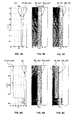
- Figures 5A, 5B and 5C correspond to the first example relating to a smooth mud velocity variation with depth.
- Figure 5A shows estimated mud velocity Vmud_est1 curve as a function of depth and estimated according to the method of the invention. The estimated mud velocity Vmud_est1 curve is compared to the constant mud velocity V0 hypothesis.
- Figure 5B shows estimated inner casing radius IR_est1 and outer casing radius OR_est1 curves as a function of depth and estimated according to the method of the invention.
- Figure 5C shows a prior art computed inner casing radius IR_PA and outer casing radius OR_PA curves as a function of depth. The prior art inner casing radius and outer casing radius are calculated base on a constant mud velocity V0 hypothesis. The curves obtained with the method of the invention results in a correct and accurate determination of the mud velocity and casing dimension.
- Figures 6A, 6B and 6C correspond to the second example relating to varying mud velocities with depth.
- Figure 6A shows estimated mud velocity Vmud_est2 curve as a function of depth and estimated according to the method of the invention. The estimated mud velocity Vmud_est2 curve is compared to the constant mud velocity V0' hypothesis.
- Figure 6B shows estimated inner casing radius IR_est2 and outer casing radius OR_est2 curves as a function of depth and estimated according to the method of the invention.
- Figure 6C shows a prior art computed inner casing radius IR_PA' and outer casing radius OR_PA' curves as a function of depth.
- the prior art inner casing radius and outer casing radius are calculated base on a constant mud velocity V0' hypothesis.
- the curves obtained with the method of the invention results in a correct and accurate determination of the mud velocity and casing dimension because the delay to detect the change of mud velocity is minimized compared to prior art method.
Landscapes
- Physics & Mathematics (AREA)
- Mining & Mineral Resources (AREA)
- Geology (AREA)
- Life Sciences & Earth Sciences (AREA)
- Engineering & Computer Science (AREA)
- Fluid Mechanics (AREA)
- Environmental & Geological Engineering (AREA)
- Geophysics (AREA)
- General Life Sciences & Earth Sciences (AREA)
- Geochemistry & Mineralogy (AREA)
- Acoustics & Sound (AREA)
- Investigating Or Analyzing Materials By The Use Of Ultrasonic Waves (AREA)
- Measurement Of Velocity Or Position Using Acoustic Or Ultrasonic Waves (AREA)
Priority Applications (2)
| Application Number | Priority Date | Filing Date | Title |
|---|---|---|---|
| EP05291356A EP1736634A1 (de) | 2005-06-24 | 2005-06-24 | Ein Ultraschallschätzungsverfahren und Vorrichtung für ein verrohrtes Bohrloch |
| US11/426,046 US7617052B2 (en) | 2005-06-24 | 2006-06-23 | Ultrasonic estimating method and apparatus for a cased well |
Applications Claiming Priority (1)
| Application Number | Priority Date | Filing Date | Title |
|---|---|---|---|
| EP05291356A EP1736634A1 (de) | 2005-06-24 | 2005-06-24 | Ein Ultraschallschätzungsverfahren und Vorrichtung für ein verrohrtes Bohrloch |
Publications (1)
| Publication Number | Publication Date |
|---|---|
| EP1736634A1 true EP1736634A1 (de) | 2006-12-27 |
Family
ID=35207815
Family Applications (1)
| Application Number | Title | Priority Date | Filing Date |
|---|---|---|---|
| EP05291356A Withdrawn EP1736634A1 (de) | 2005-06-24 | 2005-06-24 | Ein Ultraschallschätzungsverfahren und Vorrichtung für ein verrohrtes Bohrloch |
Country Status (2)
| Country | Link |
|---|---|
| US (1) | US7617052B2 (de) |
| EP (1) | EP1736634A1 (de) |
Families Citing this family (8)
| Publication number | Priority date | Publication date | Assignee | Title |
|---|---|---|---|---|
| US7628202B2 (en) * | 2007-06-28 | 2009-12-08 | Xerox Corporation | Enhanced oil recovery using multiple sonic sources |
| WO2016145524A1 (en) | 2015-03-16 | 2016-09-22 | Darkvision Technologies Inc. | Device and method to image flow in oil and gas wells using phased array doppler ultrasound |
| GB2601942B (en) | 2015-06-17 | 2022-09-14 | Darkvision Tech Inc | Ultrasonic imaging device and method for wells |
| US9938820B2 (en) | 2015-07-01 | 2018-04-10 | Saudi Arabian Oil Company | Detecting gas in a wellbore fluid |
| CA2999363C (en) | 2015-10-09 | 2023-02-21 | Osman S. MALIK | Devices and methods for imaging wells using phased array ultrasound |
| US11726224B2 (en) * | 2019-01-24 | 2023-08-15 | Baker Hughes, A Ge Company, Llc | B annulus acoustic pressure sensing |
| US12061112B2 (en) * | 2021-08-06 | 2024-08-13 | Viken Detection Corporation | Device and method for determining a material composition of a pipe |
| CN116411937A (zh) * | 2023-02-17 | 2023-07-11 | 中国石油天然气股份有限公司 | 一种测井工具、套管及过油管测生产套管固井质量的方法 |
Citations (6)
| Publication number | Priority date | Publication date | Assignee | Title |
|---|---|---|---|---|
| EP0075997A2 (de) * | 1981-09-25 | 1983-04-06 | Sigma Research, Inc. | Bohrungsvorrichtung |
| US4545242A (en) * | 1982-10-27 | 1985-10-08 | Schlumberger Technology Corporation | Method and apparatus for measuring the depth of a tool in a borehole |
| US4685092A (en) | 1984-09-05 | 1987-08-04 | Schlumberger Technology Corporation | Method and apparatus for the acoustic inspection of a borehole fitted with casing |
| US6188643B1 (en) | 1994-10-13 | 2001-02-13 | Schlumberger Technology Corporation | Method and apparatus for inspecting well bore casing |
| US20040095847A1 (en) * | 2002-11-18 | 2004-05-20 | Baker Hughes Incorporated | Acoustic devices to measure ultrasound velocity in drilling mud |
| EP1505252A1 (de) * | 2003-08-08 | 2005-02-09 | Services Petroliers Schlumberger | Multimodale akustische Bilderzeugung in verrohrten Bohrlöchern |
Family Cites Families (2)
| Publication number | Priority date | Publication date | Assignee | Title |
|---|---|---|---|---|
| US4698792A (en) * | 1984-12-28 | 1987-10-06 | Schlumberger Technology Corporation | Method and apparatus for acoustic dipole shear wave well logging |
| US6041861A (en) * | 1997-12-17 | 2000-03-28 | Halliburton Energy Services, Inc. | Method to determine self-calibrated circumferential cased bond impedance |
-
2005
- 2005-06-24 EP EP05291356A patent/EP1736634A1/de not_active Withdrawn
-
2006
- 2006-06-23 US US11/426,046 patent/US7617052B2/en not_active Expired - Fee Related
Patent Citations (6)
| Publication number | Priority date | Publication date | Assignee | Title |
|---|---|---|---|---|
| EP0075997A2 (de) * | 1981-09-25 | 1983-04-06 | Sigma Research, Inc. | Bohrungsvorrichtung |
| US4545242A (en) * | 1982-10-27 | 1985-10-08 | Schlumberger Technology Corporation | Method and apparatus for measuring the depth of a tool in a borehole |
| US4685092A (en) | 1984-09-05 | 1987-08-04 | Schlumberger Technology Corporation | Method and apparatus for the acoustic inspection of a borehole fitted with casing |
| US6188643B1 (en) | 1994-10-13 | 2001-02-13 | Schlumberger Technology Corporation | Method and apparatus for inspecting well bore casing |
| US20040095847A1 (en) * | 2002-11-18 | 2004-05-20 | Baker Hughes Incorporated | Acoustic devices to measure ultrasound velocity in drilling mud |
| EP1505252A1 (de) * | 2003-08-08 | 2005-02-09 | Services Petroliers Schlumberger | Multimodale akustische Bilderzeugung in verrohrten Bohrlöchern |
Also Published As
| Publication number | Publication date |
|---|---|
| US20060289155A1 (en) | 2006-12-28 |
| US7617052B2 (en) | 2009-11-10 |
Similar Documents
| Publication | Publication Date | Title |
|---|---|---|
| US7587936B2 (en) | Apparatus and method for determining drilling fluid acoustic properties | |
| US12055032B2 (en) | Flexural wave measurement for thick casings | |
| US9784875B2 (en) | Method to estimate cement acoustic wave speeds from data acquired by a cased hole ultrasonic cement evaluation tool | |
| JP3839376B2 (ja) | ボアホール流体音響特性の自己較正超音波現場測定方法 | |
| US10539699B2 (en) | Cement evaluation using the integration of multiple modes of acoustic measurements | |
| US9903973B2 (en) | Systems and methods for removing coherent noise in log data | |
| EP0638823A2 (de) | Ultraschallsonde zur Abstandsmessung | |
| US20160209539A1 (en) | Method for Separating Multi-Modal Acoustic Measurements for Evaluating Multilayer Structures | |
| EP3179277A1 (de) | Resonanzbasierte inversion von akustischer impedanz eines annulus hinter einem gehäuse | |
| NO20161857A1 (en) | Acoustic calipering and analysis of annulus materials | |
| US11719090B2 (en) | Enhanced cement bond and micro-annulus detection and analysis | |
| US10114138B2 (en) | Method to denoise pulse echo measurement using tool response in front of collars | |
| US20170176622A1 (en) | Techniques for removing interface noise from acoustic log data | |
| US10416329B2 (en) | Coherent noise estimation and reduction for acoustic downhole measurements | |
| US12234719B2 (en) | Methods for determining a position of a droppable object in a wellbore | |
| US7617052B2 (en) | Ultrasonic estimating method and apparatus for a cased well | |
| EP3578754B1 (de) | Verfahren zur automatischen kalibrierung eines bohrlochwerkzeugs in einer umgebung auf ölbasiertem schlamm | |
| EP0657622A2 (de) | Verfahren und Vorrichtung zur Messung des Abstandes zwischen Bohrstrang und Bohrlochwand sowie der Schallgeschwindigkeit in der Bohrspülung während des Bohrens | |
| EP3995865B1 (de) | Automatische erkennung von umgebungsparametern mit azimutal verteilten wandlern | |
| EP3035083B1 (de) | System und Verfahren zur Rauschunterdrückung in akustischen Impedanzprotokollen | |
| US11353608B2 (en) | Method for determining a property of a material behind a borehole casing | |
| CA2203361A1 (en) | Method for acoustic determination of the length of a fluid conduit | |
| US20080105426A1 (en) | Method and Apparatus for Estimating the Permeability Distribution During a Well Test | |
| Janzen et al. | Correlation between CPT data and shear wave velocity from seismic CPTs and borehole geophysical logging in dense sands of the German Bight |
Legal Events
| Date | Code | Title | Description |
|---|---|---|---|
| PUAI | Public reference made under article 153(3) epc to a published international application that has entered the european phase |
Free format text: ORIGINAL CODE: 0009012 |
|
| AK | Designated contracting states |
Kind code of ref document: A1 Designated state(s): AT BE BG CH CY CZ DE DK EE ES FI FR GB GR HU IE IS IT LI LT LU MC NL PL PT RO SE SI SK TR |
|
| AX | Request for extension of the european patent |
Extension state: AL BA HR LV MK YU |
|
| 17P | Request for examination filed |
Effective date: 20070619 |
|
| 17Q | First examination report despatched |
Effective date: 20070718 |
|
| AKX | Designation fees paid |
Designated state(s): AT BE BG CH CY CZ DE DK EE ES FI FR GB GR HU IE IS IT LI LT LU MC NL PL PT RO SE SI SK TR |
|
| STAA | Information on the status of an ep patent application or granted ep patent |
Free format text: STATUS: THE APPLICATION IS DEEMED TO BE WITHDRAWN |
|
| 18D | Application deemed to be withdrawn |
Effective date: 20160412 |