EP1736637A1 - Drehsperrvorrichtung für eine Spannmutter - Google Patents
Drehsperrvorrichtung für eine Spannmutter Download PDFInfo
- Publication number
- EP1736637A1 EP1736637A1 EP06115891A EP06115891A EP1736637A1 EP 1736637 A1 EP1736637 A1 EP 1736637A1 EP 06115891 A EP06115891 A EP 06115891A EP 06115891 A EP06115891 A EP 06115891A EP 1736637 A1 EP1736637 A1 EP 1736637A1
- Authority
- EP
- European Patent Office
- Prior art keywords
- shaft
- locking device
- nut
- clamping nut
- rotation
- Prior art date
- Legal status (The legal status is an assumption and is not a legal conclusion. Google has not performed a legal analysis and makes no representation as to the accuracy of the status listed.)
- Granted
Links
Images


Classifications
-
- F—MECHANICAL ENGINEERING; LIGHTING; HEATING; WEAPONS; BLASTING
- F01—MACHINES OR ENGINES IN GENERAL; ENGINE PLANTS IN GENERAL; STEAM ENGINES
- F01D—NON-POSITIVE DISPLACEMENT MACHINES OR ENGINES, e.g. STEAM TURBINES
- F01D25/00—Component parts, details, or accessories, not provided for in, or of interest apart from, other groups
- F01D25/16—Arrangement of bearings; Supporting or mounting bearings in casings
- F01D25/162—Bearing supports
-
- F—MECHANICAL ENGINEERING; LIGHTING; HEATING; WEAPONS; BLASTING
- F16—ENGINEERING ELEMENTS AND UNITS; GENERAL MEASURES FOR PRODUCING AND MAINTAINING EFFECTIVE FUNCTIONING OF MACHINES OR INSTALLATIONS; THERMAL INSULATION IN GENERAL
- F16B—DEVICES FOR FASTENING OR SECURING CONSTRUCTIONAL ELEMENTS OR MACHINE PARTS TOGETHER, e.g. NAILS, BOLTS, CIRCLIPS, CLAMPS, CLIPS OR WEDGES; JOINTS OR JOINTING
- F16B39/00—Locking of screws, bolts or nuts
- F16B39/02—Locking of screws, bolts or nuts in which the locking takes place after screwing down
- F16B39/04—Locking of screws, bolts or nuts in which the locking takes place after screwing down with a member penetrating the screw-threaded surface of at least one part, e.g. a pin, a wedge, cotter-pin, screw
- F16B39/06—Locking of screws, bolts or nuts in which the locking takes place after screwing down with a member penetrating the screw-threaded surface of at least one part, e.g. a pin, a wedge, cotter-pin, screw with a pin or staple parallel to the bolt axis
-
- F—MECHANICAL ENGINEERING; LIGHTING; HEATING; WEAPONS; BLASTING
- F16—ENGINEERING ELEMENTS AND UNITS; GENERAL MEASURES FOR PRODUCING AND MAINTAINING EFFECTIVE FUNCTIONING OF MACHINES OR INSTALLATIONS; THERMAL INSULATION IN GENERAL
- F16C—SHAFTS; FLEXIBLE SHAFTS; ELEMENTS OR CRANKSHAFT MECHANISMS; ROTARY BODIES OTHER THAN GEARING ELEMENTS; BEARINGS
- F16C35/00—Rigid support of bearing units; Housings, e.g. caps, covers
- F16C35/04—Rigid support of bearing units; Housings, e.g. caps, covers in the case of ball or roller bearings
- F16C35/06—Mounting or dismounting of ball or roller bearings; Fixing them onto shaft or in housing
- F16C35/067—Fixing them in a housing
-
- F—MECHANICAL ENGINEERING; LIGHTING; HEATING; WEAPONS; BLASTING
- F05—INDEXING SCHEMES RELATING TO ENGINES OR PUMPS IN VARIOUS SUBCLASSES OF CLASSES F01-F04
- F05B—INDEXING SCHEME RELATING TO WIND, SPRING, WEIGHT, INERTIA OR LIKE MOTORS, TO MACHINES OR ENGINES FOR LIQUIDS COVERED BY SUBCLASSES F03B, F03D AND F03G
- F05B2260/00—Function
- F05B2260/30—Retaining components in desired mutual position
- F05B2260/301—Retaining bolts or nuts
-
- F—MECHANICAL ENGINEERING; LIGHTING; HEATING; WEAPONS; BLASTING
- F05—INDEXING SCHEMES RELATING TO ENGINES OR PUMPS IN VARIOUS SUBCLASSES OF CLASSES F01-F04
- F05D—INDEXING SCHEME FOR ASPECTS RELATING TO NON-POSITIVE-DISPLACEMENT MACHINES OR ENGINES, GAS-TURBINES OR JET-PROPULSION PLANTS
- F05D2230/00—Manufacture
- F05D2230/60—Assembly methods
- F05D2230/64—Assembly methods using positioning or alignment devices for aligning or centring, e.g. pins
-
- F—MECHANICAL ENGINEERING; LIGHTING; HEATING; WEAPONS; BLASTING
- F05—INDEXING SCHEMES RELATING TO ENGINES OR PUMPS IN VARIOUS SUBCLASSES OF CLASSES F01-F04
- F05D—INDEXING SCHEME FOR ASPECTS RELATING TO NON-POSITIVE-DISPLACEMENT MACHINES OR ENGINES, GAS-TURBINES OR JET-PROPULSION PLANTS
- F05D2250/00—Geometry
- F05D2250/10—Two-dimensional
- F05D2250/18—Two-dimensional patterned
- F05D2250/182—Two-dimensional patterned crenellated, notched
-
- F—MECHANICAL ENGINEERING; LIGHTING; HEATING; WEAPONS; BLASTING
- F16—ENGINEERING ELEMENTS AND UNITS; GENERAL MEASURES FOR PRODUCING AND MAINTAINING EFFECTIVE FUNCTIONING OF MACHINES OR INSTALLATIONS; THERMAL INSULATION IN GENERAL
- F16C—SHAFTS; FLEXIBLE SHAFTS; ELEMENTS OR CRANKSHAFT MECHANISMS; ROTARY BODIES OTHER THAN GEARING ELEMENTS; BEARINGS
- F16C2360/00—Engines or pumps
- F16C2360/23—Gas turbine engines
-
- Y—GENERAL TAGGING OF NEW TECHNOLOGICAL DEVELOPMENTS; GENERAL TAGGING OF CROSS-SECTIONAL TECHNOLOGIES SPANNING OVER SEVERAL SECTIONS OF THE IPC; TECHNICAL SUBJECTS COVERED BY FORMER USPC CROSS-REFERENCE ART COLLECTIONS [XRACs] AND DIGESTS
- Y10—TECHNICAL SUBJECTS COVERED BY FORMER USPC
- Y10T—TECHNICAL SUBJECTS COVERED BY FORMER US CLASSIFICATION
- Y10T403/00—Joints and connections
- Y10T403/49—Member deformed in situ
Definitions
- the present invention relates to the technical field of maintaining a part inside an end of a hollow shaft or a journal of a turbomachine such as an aircraft engine, said part possibly being a bearing outer ring.
- the invention relates to a locking device in rotation of a clamping nut of a workpiece on an end of a hollow shaft.
- the invention also relates to a clamping nut adapted to be locked in rotation by such a locking device in rotation.
- the invention also relates to a hollow shaft of a turbomachine, intended to cooperate with such a clamping nut.
- the invention finally relates to an aircraft engine equipped with such a rotational locking device and / or such a clamping nut and / or such a hollow shaft.
- axial refers to the axial direction of the turbomachine.
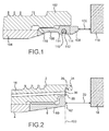
- FIG. 1 which represents a configuration of the prior art, are represented a hollow shaft 102 of a high-pressure turbine of a turbomachine such as an aircraft engine, an outer race ring 104 fitted inside this shaft 102, and a clamping nut 106 of this outer ring 104.
- the clamping nut 106 is screwed into the shaft 102, and presses against the outer race ring 104 to hold it in place.
- the free end 108 of the clamping nut 106 protrudes axially with respect to the end of the shaft 102, and comprises clamping notches, which are recesses in which it is possible to slide a tool to screw the clamping nut 106.
- the clamping nut 106 is provided with a rotational locking device 110, 112, 114 having an anti-rotation ring 110 housed in a groove 112 of the clamping nut 106, this groove 112 opening radially towards the end.
- the inside of the clamping nut 106 On either side of the groove 112 are raised portions 114 of the clamping nut 106, which have an irregular surface and sharp edges.
- An oil circulation duct 116 is provided through the clamping nut 106 so as to allow an oil supply between the shaft 102 and the outer bearing ring 104.
- the end of the shaft 102 of the high pressure turbine is facing an end of a shaft 118 of a low pressure turbine (shown schematically on the right of Figure 1).
- the distance The axial axis between the high pressure turbine shaft 102 and the low pressure turbine shaft 118 is designated 120.
- a first disadvantage derives from the fact that during the operation of the turbomachine, the high pressure turbine shaft 102 and the low pressure turbine shaft 118 are subjected to respective displacements independent of one another and to expansions due to in the heat. This results in relative displacements, especially along the axial direction, between the high-pressure turbine shaft 102 and the low-pressure turbine shaft 118.
- the distance 120 between the shaft 102 and the shaft 118 it is desirable for the distance 120 between the shaft 102 and the shaft 118 to be as large as possible, while providing the turbomachine a congestion as small as possible.
- the clamping nut does not hurt the rolling parts during their assembly.
- the invention proposes to overcome the disadvantages mentioned above.
- the invention relates to a locking device in rotation of a clamping nut of a workpiece, in particular an outer race, on one end of a hollow shaft having an axial direction, said nut clamping means being screwed into said shaft, and said clamping nut having an end in contact with said workpiece and a free end.
- the rotational locking device comprises an odd number of shaft blanks and an even number of blanks.
- the rotational locking device further comprises a retaining ring of said locking pin in an axial direction.
- the retention ring further comprises at least one retaining tab extending radially inwards, the number of retaining tabs being identical to the number of tree blanks.
- said retention ring has notches which open radially inward, each notch being located between two successive retention tabs.
- said rotational locking device comprises a finger on said retention ring and a notch of the shaft, which cooperate to prevent axial rotation of said retention ring.
- said notch is opposite a shaft cutout on an axially projecting end flange of the shaft.
- said finger extends radially outward facing one of said retention tabs.
- said retention ring is provided with a mounting slot.
- said mounting slot and said finger are positioned diametrically opposite on said retention ring.
- the rotational locking device further comprises a receiving groove for receiving said retention ring, formed on a radially inner end face of the shaft.
- the invention relates to a nut for clamping a workpiece inside an end of a hollow shaft, said nut having an end in contact with said outer race and a free end, characterized in that it is adapted to be locked in rotation by a rotational locking device according to the first aspect of the invention, and in that it comprises at least one nut cutout, on the radially outer periphery of its free end.
- said clamping nut further comprises a radially inner face which is substantially smooth and which flares towards its free end.
- the invention relates to a hollow shaft intended to cooperate with a clamping nut for holding a part inside one of its ends, characterized in that it is adapted to be locked in rotation by a device for rotational locking according to the second aspect of the invention, and in that it comprises at least one shaft cutout, on the radially inner periphery of said end of said shaft, and a receiving groove formed on an inner face of an end flange of said shaft.
- the invention relates to an aircraft engine, equipped with at least one rotational locking device according to the first aspect and / or at least one clamping nut according to the second aspect and / or at least one hollow shaft according to the third aspect.
- FIG. 2 there is shown a hollow shaft 2 of a turbine of a turbomachine.
- this hollow shaft 2 is disposed an outer bearing ring 4, which is introduced by a free end of the hollow shaft 2.
- the outer bearing ring 4 is held in place by means of a clamping nut 6, which is introduced thereafter by the end of the hollow shaft 2 and holding it in place.
- the clamping nut 6 is provided with an external thread which cooperates with an internal thread of the hollow shaft 2.
- the clamping nut 6 has an end which is in contact with the outer race, and a free end.
- the references 22 and 62 designate, respectively, a free end face of the hollow shaft 2 and a free end face of the clamping nut 6, these two respective end faces 22, 62 being substantially contained in the same end radial plane 100 (see Figure 2).
- Mark 20 designates the axial distance separating this radial end plane 100 from a shaft of a low pressure turbine 18 (shown schematically on the right of FIG. 2)
- the hollow shaft 2 comprises a shaft flange 24 which extends axially from the end face 22, and in which is formed, substantially perpendicular to the radial plane 100, a groove 26 opening radially. towards the inside of the tree 2.
- the hollow shaft 2 comprises shaft cutouts 28 distributed over its radially inner periphery and which also open on its end face 22.
- the hollow shaft 2 is traversed by oil passages 16, which allow an oil return circulation between the outer race ring 4 and the end face 22 of the shaft 2, and which open on this face. end 22 in orifices 30.
- the clamping nut 6 has a flange 64, which extends radially outwards and ends with its end face 62.
- the clamping nut 6 comprises clamping notches 66, which are recesses distributed over the radially outer periphery of the flange 64, and which also open on its end face 62.
- the clamping nut 6 has nut blanks 68 distributed radially around the periphery. outer collar 64, and which also open on its end face 62.
- Figure 3 is a front perspective view showing the clamping nut 6 and a portion of the hollow shaft 2.
- the clamping nut has six notches of 66 and twelve nut cutouts 68, while the shaft 2 has thirteen shaft cutouts 28.
- the locking device in rotation of the clamping nut 6 comprises the shaft cutouts 28 and the nut cutouts 68. It also comprises a locking pin 8. To lock the clamping nut 6 in rotation, turn the latter relative to the hollow shaft 2 until one of the nut blanks 68 is in register with one of the cutouts 28. The two cutouts 68, 28 thus set coincidence form a blocking hole 682 into which the locking pin 8 is inserted.
- FIG. 5 illustrates, in enlarged view, the locking in rotation of the clamping nut 6. It shows a portion of the clamping nut 6 and a portion of the hollow shaft 2 at a blocking hole 682 in which is inserted a blocking pin 8.
- the shaft cutouts 28 and the nut blanks 68 have a circular contour, so that the blocking hole 682 has a section circular.
- the locking pin 8 also has a circular section.
- the locking device in rotation of the clamping nut 6 also preferably comprises a retaining ring 40, which retains the locking pin 8 in the axial direction after the locking pin has been inserted into the locking hole. 682.
- the axial retention ring 40 is also shown in FIG.
- the rotational locking device also comprises the groove 26 of the hollow shaft 2 which is a receiving groove for the retention ring 40.
- the diameter of the retention ring 40 and the depth of the receiving groove 26 are arranged to allow the insertion and retention of the retaining ring 40 in the groove 26.
- the retention ring 40 has retention lugs 42 which extend radially inwardly. These retention lugs 42 are distributed around its circumference and their number is identical to the number of shaft cuts 28, so that for a particular angular position of the retention ring 40 in the receiving groove 26, each lug of Retention 42 covers a shaft cutout 68. Between the retention lugs 42, the retention ring 40 has notches 44 which open radially inwardly.
- the retention ring 40 further includes a finger 48 which extends radially outwardly from its outer periphery.
- a finger 48 which extends radially outwardly from its outer periphery.
- the rim 24 of the shaft 2 is interrupted by a notch 50, situated opposite one of the 280 of the cutouts 28.
- the tightening nut 6 is rotated until the shaft cutout 280 facing which the notch 50 coincides with the one 680 of the nut blanks 68. Then a locking pin 8 is inserted into the locking hole 682 formed by the coincidence of this tree cutout 280 with this blank Nut 680. Then the retention ring 40 is inserted into the receiving groove 26 and positioned so that the finger 48 is inserted into the notch 50.
- the retaining ring 40 is immobilized in rotation with respect to the shaft 2, and therefore with respect to the locking hole 682 in which the locking pin 8 has been placed.
- This locking pin 8 is retained axially by one of the retaining lugs 42 of the retention ring 40.
- This locking pin 8 can not escape from the locking hole 682.
- the presence of the locking pin 8 prevents a rotation of the clamping nut 6 relative to the shaft 2.
- the retaining ring 40 further comprises a mounting slot 52 which makes it possible to open the retention ring 40 in order to deform it and temporarily reduce its diameter, in order to introduce it into the receiving groove 26.
- the mounting slot 52 is positioned on the retention ring 40 so as to be diametrically opposed to the finger 48.
- An advantage of the configuration of the retention ring 40 according to the invention lies in the fact that the presence of the notches 44 allows the orifices 30 of the oil passages 32 to remain clear when the rotational locking device is installed. This does not disturb the return of oil from the bearing ring 4.
- the clamping nut 6 has, in addition, a radially inner face 60 which is smooth and which flares towards its free end. In other words, the clamping nut has a conical opening. This particular geometry of the clamping nut 6 makes it possible to avoid catching or injuring the complementary rolling elements of the outer race ring 4 during their assembly.
- the rotational locking device according to the invention has a significant advantage over those of the prior art which have been previously discussed. Indeed, as can be seen by comparing FIGS. 1 and 2, the distance 20 between the high-pressure turbine shaft 2 and the low-pressure turbine shaft 18 according to the invention is greater than the distance 120 between the shaft high pressure turbine 102 and the low pressure turbine shaft 118 according to the prior art.
- the configuration of the locking device according to the invention therefore allows axial displacements of larger trees than the prior art.
- the hollow shaft has a number of shaft cutouts other than 13, and that the clamping nut has a number of nut cutouts other than 12. It is necessary, however, that the number of tree blanks and the number of blanks are different from each other. Preferably, one of these numbers is an even number and the other of these numbers is an odd number.
- the shaft blanks and the nut blanks have a shape different from a circular shape, and that the locking pin has a shape complementary to that of the hole of the invention. locking formed by the coincidence of one of the shaft holes with one of the nut holes.
- the invention which has just been described in the detailed description which precedes illustrates a locking device in rotation of a tightening nut of an outer race ring.
- the invention could be applied to a part other than an outer race, which must be held in place by a clamping nut inside a hollow shaft, near one end thereof .
Landscapes
- Engineering & Computer Science (AREA)
- General Engineering & Computer Science (AREA)
- Mechanical Engineering (AREA)
- Mounting Of Bearings Or Others (AREA)
- Snaps, Bayonet Connections, Set Pins, And Snap Rings (AREA)
- Clamps And Clips (AREA)
- Rolling Contact Bearings (AREA)
Applications Claiming Priority (1)
| Application Number | Priority Date | Filing Date | Title |
|---|---|---|---|
| FR0551748A FR2887599B1 (fr) | 2005-06-24 | 2005-06-24 | Dispositif de blocage en rotation d'un ecrou de serrage d'une piece sur un arbre, ecrou de serrage et arbre le comportant, et moteur d'aeronef en etant equipe |
Publications (2)
| Publication Number | Publication Date |
|---|---|
| EP1736637A1 true EP1736637A1 (de) | 2006-12-27 |
| EP1736637B1 EP1736637B1 (de) | 2016-01-13 |
Family
ID=36010449
Family Applications (1)
| Application Number | Title | Priority Date | Filing Date |
|---|---|---|---|
| EP06115891.1A Active EP1736637B1 (de) | 2005-06-24 | 2006-06-22 | Drehsperrvorrichtung für eine Spannmutter |
Country Status (5)
| Country | Link |
|---|---|
| US (1) | US7661928B2 (de) |
| EP (1) | EP1736637B1 (de) |
| CA (1) | CA2550784C (de) |
| FR (1) | FR2887599B1 (de) |
| RU (1) | RU2397378C2 (de) |
Cited By (3)
| Publication number | Priority date | Publication date | Assignee | Title |
|---|---|---|---|---|
| FR2932221A1 (fr) * | 2008-06-04 | 2009-12-11 | Snecma | Tourillon support de palier et ensemble d'un tel tourillon et d'un fourreau d'etancheite |
| FR2982636A1 (fr) * | 2011-11-16 | 2013-05-17 | Snecma | Palier a roulement pour turboreacteur d'aeronef comprenant des moyens ameliores de retention axiale de sa bague exterieure |
| FR3041555A1 (fr) * | 2015-09-29 | 2017-03-31 | Snecma | Agencement comprenant un ecrou visse a une piece mecanique, un pion d'arret en rotation de l'ecrou et un segment circulaire retenant le pion et arrete en rotation |
Families Citing this family (9)
| Publication number | Priority date | Publication date | Assignee | Title |
|---|---|---|---|---|
| US20100143031A1 (en) * | 2009-03-03 | 2010-06-10 | Remy Technologies, L.L.C. | Mechanical fastener having a thread staking mechanism |
| US8460118B2 (en) * | 2011-08-31 | 2013-06-11 | United Technologies Corporation | Shaft assembly for a gas turbine engine |
| WO2014058463A1 (en) | 2012-10-09 | 2014-04-17 | United Technologies Corporation | Geared turbofan engine with inter-shaft deflection feature |
| US11143032B2 (en) | 2018-10-29 | 2021-10-12 | Raytheon Technologies Corporation | Turbine rotor locking assembly and method |
| CN110332300A (zh) * | 2019-07-11 | 2019-10-15 | 中国航发哈尔滨东安发动机有限公司 | 一种轴承的端面压紧结构 |
| US11480071B2 (en) * | 2020-06-02 | 2022-10-25 | Pratt & Whitney Canada Corp. | Balancing ring geometry |
| US11560807B2 (en) | 2021-04-29 | 2023-01-24 | Pratt & Whitney Canada Corp. | Internal retaining ring for a rotating assembly in a gas turbine engine |
| KR102731845B1 (ko) * | 2022-06-29 | 2024-11-18 | 대원정밀공업(주) | 회전 중심이 안정적으로 유지되는 차량용 시트 스위블 장치 |
| US12203502B2 (en) * | 2022-12-12 | 2025-01-21 | Schaeffler Technologies AG & Co. KG | Bearing housing assembly and ring configured to provide multiple modes of operation |
Citations (7)
| Publication number | Priority date | Publication date | Assignee | Title |
|---|---|---|---|---|
| US3541624A (en) * | 1967-12-20 | 1970-11-24 | Standard Pressed Steel Co | Method of making a bolt |
| DE2439448A1 (de) * | 1974-08-16 | 1976-03-04 | Hans Gert Meier | Stiftsicherung |
| US4037980A (en) | 1975-12-24 | 1977-07-26 | Haentjens Walter D | Pump coupling |
| US4046430A (en) * | 1976-03-12 | 1977-09-06 | United Technologies Corporation | Damped intershaft bearing and stabilizer |
| US4175803A (en) * | 1977-06-14 | 1979-11-27 | Rolls-Royce Limited | Bearing assembly between inner and outer shafts having two roller bearings and two hydrodynamic or squeeze film bearings |
| US4884903A (en) * | 1988-03-30 | 1989-12-05 | Societe Nationale D'etude Et De Construction De Moteurs D'aviation "S.N.E.C.M.A." | Inter-shaft bearing for multiple body turbo-engines |
| US20030044097A1 (en) * | 2001-08-31 | 2003-03-06 | Trapp Michael Kelly | Retainer nut |
Family Cites Families (2)
| Publication number | Priority date | Publication date | Assignee | Title |
|---|---|---|---|---|
| SU69541A1 (ru) * | 1946-05-10 | 1946-11-30 | Ю.К. Жуков | Приспособление против самопроизвольного отвинчивани гаек |
| SU898137A1 (ru) * | 1980-04-18 | 1982-01-15 | Предприятие П/Я В-2827 | Резьбовое соединение |
-
2005
- 2005-06-24 FR FR0551748A patent/FR2887599B1/fr not_active Expired - Lifetime
-
2006
- 2006-06-21 US US11/425,540 patent/US7661928B2/en active Active
- 2006-06-22 EP EP06115891.1A patent/EP1736637B1/de active Active
- 2006-06-23 CA CA2550784A patent/CA2550784C/fr active Active
- 2006-06-23 RU RU2006122619/11A patent/RU2397378C2/ru active
Patent Citations (7)
| Publication number | Priority date | Publication date | Assignee | Title |
|---|---|---|---|---|
| US3541624A (en) * | 1967-12-20 | 1970-11-24 | Standard Pressed Steel Co | Method of making a bolt |
| DE2439448A1 (de) * | 1974-08-16 | 1976-03-04 | Hans Gert Meier | Stiftsicherung |
| US4037980A (en) | 1975-12-24 | 1977-07-26 | Haentjens Walter D | Pump coupling |
| US4046430A (en) * | 1976-03-12 | 1977-09-06 | United Technologies Corporation | Damped intershaft bearing and stabilizer |
| US4175803A (en) * | 1977-06-14 | 1979-11-27 | Rolls-Royce Limited | Bearing assembly between inner and outer shafts having two roller bearings and two hydrodynamic or squeeze film bearings |
| US4884903A (en) * | 1988-03-30 | 1989-12-05 | Societe Nationale D'etude Et De Construction De Moteurs D'aviation "S.N.E.C.M.A." | Inter-shaft bearing for multiple body turbo-engines |
| US20030044097A1 (en) * | 2001-08-31 | 2003-03-06 | Trapp Michael Kelly | Retainer nut |
Cited By (4)
| Publication number | Priority date | Publication date | Assignee | Title |
|---|---|---|---|---|
| FR2932221A1 (fr) * | 2008-06-04 | 2009-12-11 | Snecma | Tourillon support de palier et ensemble d'un tel tourillon et d'un fourreau d'etancheite |
| US8303189B2 (en) | 2008-06-04 | 2012-11-06 | Snecma | Bearing support journal and assembly of such a journal and a sealing sleeve |
| FR2982636A1 (fr) * | 2011-11-16 | 2013-05-17 | Snecma | Palier a roulement pour turboreacteur d'aeronef comprenant des moyens ameliores de retention axiale de sa bague exterieure |
| FR3041555A1 (fr) * | 2015-09-29 | 2017-03-31 | Snecma | Agencement comprenant un ecrou visse a une piece mecanique, un pion d'arret en rotation de l'ecrou et un segment circulaire retenant le pion et arrete en rotation |
Also Published As
| Publication number | Publication date |
|---|---|
| EP1736637B1 (de) | 2016-01-13 |
| RU2006122619A (ru) | 2008-01-10 |
| CA2550784A1 (fr) | 2006-12-24 |
| CA2550784C (fr) | 2016-01-05 |
| US7661928B2 (en) | 2010-02-16 |
| FR2887599A1 (fr) | 2006-12-29 |
| FR2887599B1 (fr) | 2007-08-31 |
| US20060291953A1 (en) | 2006-12-28 |
| RU2397378C2 (ru) | 2010-08-20 |
Similar Documents
| Publication | Publication Date | Title |
|---|---|---|
| CA2606065C (fr) | Assemblage d'un dispositif rotulant sur une chape de renvoi d'angle, systeme de commande d'un redresseur a calage variable le comportant, et moteur d'aeronef en etant muni | |
| EP1736637B1 (de) | Drehsperrvorrichtung für eine Spannmutter | |
| EP1498624B1 (de) | Vorrichtung zur Fixierung eine Motorenwelle auf einem Lager | |
| CA2582401C (fr) | Dispositif de fixation de secteurs d'anneau autour d'une roue de turbine d'une turbomachine | |
| EP2839117B1 (de) | Turbinenstufe für eine turbomaschine | |
| EP2961573B1 (de) | Gerät, verfahren und kit für die montage eines innenrings eines rollenlagers mit einem wälzlagerkäfig und schrauben in einer turbomaschine, | |
| CA2913579A1 (fr) | Carter de turbomachine comportant un orifice d'endoscopie | |
| FR2911632A1 (fr) | Disque de rotor de soufflante de turbomachine | |
| FR3016666A1 (fr) | Dispositif de liaison a rotule. | |
| WO2016055747A1 (fr) | Assemblage de deux pièces comprenant une coupelle de centrage amovible pour turbomachine d'aéronef | |
| EP3201531B1 (de) | Brennkammer einer turbomaschine | |
| FR3082874A1 (fr) | Piece annulaire de fonderie et frettee d'une turbomachine d'aeronef | |
| EP1780427A1 (de) | Nicht einschneidende Verankerungsscheibe | |
| CA2558028C (fr) | Dispositif d'immobilisation d'un anneau de retention axiale d'une aube, disque de rotor et anneau de retention associes, et rotor et moteur d'aeronef les comportant | |
| FR2955895A1 (fr) | Turbomachine avec agencement optimise pour la fixation d'un palier d'arbre tournant. boulon pour une telle turbomachine | |
| EP4010563B1 (de) | Prallkühlvorrichtung für ein turbomaschinen-aussengehäuse und turbomaschine mit entsprechender vorrichtung | |
| FR3108538A1 (fr) | Embout a préhension par dépression pour système d’aspiration de particules | |
| EP3455466B1 (de) | Anordnung für turbomaschine mit einem verteiler, strukturelles element einer turbomaschine und anbauvorrichtung | |
| FR3078759A1 (fr) | Dispositif de poulie pour galet tendeur ou enrouleur | |
| WO2025022074A1 (fr) | Systeme de blocage d'un bouchon dans une piece de turbomachine d'aeronef, de preference un arbre de turbomachine | |
| EP3931427B1 (de) | Anordnung für eine turbine einer turbomaschine | |
| FR3015641A1 (fr) | Dispositif d'injection dans une turbomachine | |
| FR3139594A1 (fr) | Jeu d’éléments de fixation autobloquants et ensemble de rotor de turbomachine équipé d’un tel jeu. | |
| WO2025022073A1 (fr) | Systeme d'accouplement de deux pieces de turbomachine d'aeronef, de preference deux arbres de turbomachine | |
| WO2025242985A1 (fr) | Dispositif de fixation de modules de turbomachine |
Legal Events
| Date | Code | Title | Description |
|---|---|---|---|
| PUAI | Public reference made under article 153(3) epc to a published international application that has entered the european phase |
Free format text: ORIGINAL CODE: 0009012 |
|
| AK | Designated contracting states |
Kind code of ref document: A1 Designated state(s): AT BE BG CH CY CZ DE DK EE ES FI FR GB GR HU IE IS IT LI LT LU LV MC NL PL PT RO SE SI SK TR |
|
| AX | Request for extension of the european patent |
Extension state: AL BA HR MK YU |
|
| 17P | Request for examination filed |
Effective date: 20070615 |
|
| AKX | Designation fees paid |
Designated state(s): DE FR GB |
|
| 17Q | First examination report despatched |
Effective date: 20091127 |
|
| GRAP | Despatch of communication of intention to grant a patent |
Free format text: ORIGINAL CODE: EPIDOSNIGR1 |
|
| INTG | Intention to grant announced |
Effective date: 20150722 |
|
| GRAS | Grant fee paid |
Free format text: ORIGINAL CODE: EPIDOSNIGR3 |
|
| GRAA | (expected) grant |
Free format text: ORIGINAL CODE: 0009210 |
|
| AK | Designated contracting states |
Kind code of ref document: B1 Designated state(s): DE FR GB |
|
| REG | Reference to a national code |
Ref country code: GB Ref legal event code: FG4D Free format text: NOT ENGLISH |
|
| REG | Reference to a national code |
Ref country code: DE Ref legal event code: R096 Ref document number: 602006047708 Country of ref document: DE |
|
| REG | Reference to a national code |
Ref country code: FR Ref legal event code: PLFP Year of fee payment: 11 |
|
| REG | Reference to a national code |
Ref country code: DE Ref legal event code: R097 Ref document number: 602006047708 Country of ref document: DE |
|
| PLBE | No opposition filed within time limit |
Free format text: ORIGINAL CODE: 0009261 |
|
| STAA | Information on the status of an ep patent application or granted ep patent |
Free format text: STATUS: NO OPPOSITION FILED WITHIN TIME LIMIT |
|
| 26N | No opposition filed |
Effective date: 20161014 |
|
| REG | Reference to a national code |
Ref country code: FR Ref legal event code: PLFP Year of fee payment: 12 |
|
| REG | Reference to a national code |
Ref country code: FR Ref legal event code: CD Owner name: SAFRAN AIRCRAFT ENGINES, FR Effective date: 20170719 |
|
| REG | Reference to a national code |
Ref country code: FR Ref legal event code: PLFP Year of fee payment: 13 |
|
| PGFP | Annual fee paid to national office [announced via postgrant information from national office to epo] |
Ref country code: DE Payment date: 20250618 Year of fee payment: 20 |
|
| PGFP | Annual fee paid to national office [announced via postgrant information from national office to epo] |
Ref country code: GB Payment date: 20250625 Year of fee payment: 20 |
|
| PGFP | Annual fee paid to national office [announced via postgrant information from national office to epo] |
Ref country code: FR Payment date: 20250620 Year of fee payment: 20 |