EP1736669A2 - Pompe de refroidissement réglable - Google Patents
Pompe de refroidissement réglable Download PDFInfo
- Publication number
- EP1736669A2 EP1736669A2 EP06010442A EP06010442A EP1736669A2 EP 1736669 A2 EP1736669 A2 EP 1736669A2 EP 06010442 A EP06010442 A EP 06010442A EP 06010442 A EP06010442 A EP 06010442A EP 1736669 A2 EP1736669 A2 EP 1736669A2
- Authority
- EP
- European Patent Office
- Prior art keywords
- impeller
- pump
- bearing
- collar
- coolant
- Prior art date
- Legal status (The legal status is an assumption and is not a legal conclusion. Google has not performed a legal analysis and makes no representation as to the accuracy of the status listed.)
- Granted
Links
Images


Classifications
-
- F—MECHANICAL ENGINEERING; LIGHTING; HEATING; WEAPONS; BLASTING
- F04—POSITIVE - DISPLACEMENT MACHINES FOR LIQUIDS; PUMPS FOR LIQUIDS OR ELASTIC FLUIDS
- F04D—NON-POSITIVE-DISPLACEMENT PUMPS
- F04D13/00—Pumping installations or systems
- F04D13/02—Units comprising pumps and their driving means
- F04D13/021—Units comprising pumps and their driving means containing a coupling
- F04D13/022—Units comprising pumps and their driving means containing a coupling a coupling allowing slip, e.g. torque converter
-
- F—MECHANICAL ENGINEERING; LIGHTING; HEATING; WEAPONS; BLASTING
- F01—MACHINES OR ENGINES IN GENERAL; ENGINE PLANTS IN GENERAL; STEAM ENGINES
- F01P—COOLING OF MACHINES OR ENGINES IN GENERAL; COOLING OF INTERNAL-COMBUSTION ENGINES
- F01P7/00—Controlling of coolant flow
- F01P7/14—Controlling of coolant flow the coolant being liquid
- F01P7/16—Controlling of coolant flow the coolant being liquid by thermostatic control
- F01P7/162—Controlling of coolant flow the coolant being liquid by thermostatic control by cutting in and out of pumps
-
- F—MECHANICAL ENGINEERING; LIGHTING; HEATING; WEAPONS; BLASTING
- F04—POSITIVE - DISPLACEMENT MACHINES FOR LIQUIDS; PUMPS FOR LIQUIDS OR ELASTIC FLUIDS
- F04C—ROTARY-PISTON, OR OSCILLATING-PISTON, POSITIVE-DISPLACEMENT MACHINES FOR LIQUIDS; ROTARY-PISTON, OR OSCILLATING-PISTON, POSITIVE-DISPLACEMENT PUMPS
- F04C15/00—Component parts, details or accessories of machines, pumps or pumping installations, not provided for in groups F04C2/00 - F04C14/00
- F04C15/0003—Sealing arrangements in rotary-piston machines or pumps
- F04C15/0023—Axial sealings for working fluid
- F04C15/0026—Elements specially adapted for sealing of the lateral faces of intermeshing-engagement type machines or pumps, e.g. gear machines or pumps
-
- F—MECHANICAL ENGINEERING; LIGHTING; HEATING; WEAPONS; BLASTING
- F04—POSITIVE - DISPLACEMENT MACHINES FOR LIQUIDS; PUMPS FOR LIQUIDS OR ELASTIC FLUIDS
- F04C—ROTARY-PISTON, OR OSCILLATING-PISTON, POSITIVE-DISPLACEMENT MACHINES FOR LIQUIDS; ROTARY-PISTON, OR OSCILLATING-PISTON, POSITIVE-DISPLACEMENT PUMPS
- F04C2/00—Rotary-piston machines or pumps
- F04C2/08—Rotary-piston machines or pumps of intermeshing-engagement type, i.e. with engagement of co-operating members similar to that of toothed gearing
- F04C2/10—Rotary-piston machines or pumps of intermeshing-engagement type, i.e. with engagement of co-operating members similar to that of toothed gearing of internal-axis type with the outer member having more teeth or tooth-equivalents, e.g. rollers, than the inner member
- F04C2/102—Rotary-piston machines or pumps of intermeshing-engagement type, i.e. with engagement of co-operating members similar to that of toothed gearing of internal-axis type with the outer member having more teeth or tooth-equivalents, e.g. rollers, than the inner member the two members rotating simultaneously around their respective axes
-
- F—MECHANICAL ENGINEERING; LIGHTING; HEATING; WEAPONS; BLASTING
- F04—POSITIVE - DISPLACEMENT MACHINES FOR LIQUIDS; PUMPS FOR LIQUIDS OR ELASTIC FLUIDS
- F04D—NON-POSITIVE-DISPLACEMENT PUMPS
- F04D13/00—Pumping installations or systems
- F04D13/12—Combinations of two or more pumps
-
- F—MECHANICAL ENGINEERING; LIGHTING; HEATING; WEAPONS; BLASTING
- F04—POSITIVE - DISPLACEMENT MACHINES FOR LIQUIDS; PUMPS FOR LIQUIDS OR ELASTIC FLUIDS
- F04D—NON-POSITIVE-DISPLACEMENT PUMPS
- F04D15/00—Control, e.g. regulation, of pumps, pumping installations or systems
- F04D15/0066—Control, e.g. regulation, of pumps, pumping installations or systems by changing the speed, e.g. of the driving engine
Definitions
- the invention relates to a controllable coolant pump driven by torque transmission elements for internal combustion engines.
- crankshaft coolant pumps must therefore always be dimensioned so that they cause sufficient cooling performance even at low speed and high engine load - for example, when driving uphill with trailer.
- crankshaft coolant pumps Another major drawback of such directly driven by the crankshaft coolant pumps is that they begin immediately in the warm-up phase with the heat dissipation of the motor generated and actually in the warm-up phase also urgently needed in the engine heat.
- thermocouples used for this speed control generate a dependent of the respective coolant temperature frictional force, slip occurs between the pump shaft and the impeller not only briefly, which inevitably increased wear of the torque transmission surfaces occurs.
- a hydrostatic clutch with a driving, internally toothed ring gear and an eccentrically mounted, with the ring gear as a gear pump cooperating inner wheel is prescribed, which is controlled by a throttled bypass.
- the two disc parts of the impeller are connected at cold start by means of a clutch. From a predetermined speed, this clutch opens, which then promotes the pump specifically less coolant at higher speed.
- the DE 33 29 002 A1 describes, however, a controllable coolant pump with a device for displacement of the impeller as a function of the coolant temperature by means of a thermocouple to reduce with increasing coolant temperature between the radial blades of the pump impeller and the pump housing gap, and thereby to increase the coolant flow rate.
- the DE 41 42 120 A1 describes a controllable cooling water pump in which the power of the cooling water pump by the variation of the impeller adjacent gap, by means of an axially displaceable ring, can be changed.
- the drive power of the coolant pump can be varied only slightly at very poor efficiency. Due to the unfavorable design of the suction area, with the mandatory in the suction mouth webs, there is a strong cavitation. In addition, the axial adjusting device requires a large space.
- the invention is therefore based on the object to develop a driven, controllable coolant pump for internal combustion engines, which does not have the aforementioned disadvantages of the prior art, coolant temperature dependent exact and gentle, can be controlled continuously, it is wear-susceptible and störunan classroom, and high efficiency one optimal, very precisely controlled adjustment of the coolant volume flow to the heat balance of the engine significantly reduces the warm-up phase of the engine, the pollutant emissions as well as simultaneously reduces friction losses and fuel consumption, and with minimal space high functional and operational reliability over the entire Lifetime guaranteed, and is also suitable for retrofitting of existing engine generations.
- controllable coolant pump with a mounted in a pump bearing in the bearing housing, driven pump shaft, a bearing space from the pump chamber sealing gasket, preferably a mechanical seal and a freely rotatably mounted on a plain bearing of the pump shaft impeller arranged by a arranged on the pump shaft coupling depending on the temperature of the coolant is driven, characterized in that in the impeller a multi-stepped cylindrical interior with sealing collar / s and this / this Dichtbund / s adjacent, an inner toothing similar outer rotor contour is arranged, said on the pump shaft in addition to the sliding bearing for the impeller is rotatably disposed with a / two cylindrical Lagerbund / s and one / two sealing ridge / s eccentric provided, on which is rotatably provided with an external toothed inner rotor, which analo with the outer rotor contour in the impeller g is able to cooperate with the operating principle of a gerotor pump as a clutch,
- Essential to the invention is in this context also that on the / the bearing collars on one or both sides of the eccentric axially displaceable each one of the respective sealing collar reaching to each associated sealing ridge pressure plate is arranged, which between their respective investment in the sealing web and the sealing collar and a spaced from the respective sealing ridge, arranged on the associated bearing collar pressure surface is slidably mounted / are, wherein on the side facing away from the eccentric of the pressure plate / n each one rotatably mounted in the impeller bimetallic disk is fixed adjacent.
- overflow grooves are arranged in the working area of the pressure plate (s) in the annular casing of the impeller, which ensure optimum coolant exchange.
- the speed of the pump impeller approximately corresponds to the input speed of the pump shaft.
- the bimetallic disc (s) relieves / relieves the pressure plate (s).
- an abutment disc At the support surface of the seal ring according to the invention is an abutment disc to which a relative movement between the rotating at the speed of the impeller abutment disc and the revolving at the speed of the pump shaft seal ring allows, so that by means of inventive arrangement an axial displacement of the impeller on the pump shaft is avoided.
- bimetallic disc can be varied depending on the respective coolant temperature due to the inventive arrangement on the pressure plate, the gap width between the pressure plate and the sealing land or the sealing collar, so that increases with increasing gap width, the circulating between the displacement chambers coolant and thereby the driving torque between the pump shaft and impeller sink.
- the minimum, speed-dependent drag torque between the pump shaft and the impeller can be specified.
- the solution according to the invention thus enables effective control of the drive torque of the impeller of a driven coolant pump with high efficiency and thereby enables an optimal adaptation of the coolant volume flow to the heat balance of the engine.
- optimal temperature-dependent adjustable solution is also suitable for retrofitting existing engine generations.
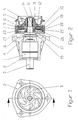
- FIG. 1 shows a design of the controllable coolant pump according to the invention in a front view, with a bearing housing 2 and a pump wheel 5.
- FIG. 2 shows this coolant pump according to the invention of FIG. 1 in section at A-A.
- FIG. 3 also shows an exploded view of the controllable coolant pump according to the invention according to FIG.
- a driven pump shaft 3 is mounted in a bearing housing 2 while a pump bearing 1 is arranged.
- a driven pump shaft 3 is mounted in this pump bearing 1.
- a seal 4 preferably a mechanical seal is arranged between the storage space and the pump chamber.
- impeller 5 is freely rotatably mounted on a arranged between the pump shaft 3 and the impeller 5 bearing bush 6.
- Bearing housing side is in the impeller 5 a multiple stepped cylindrical interior with a sealing collar 7 and a sealing collar 7 adjacent this, an internal toothing similar, outer rotor contour 8 is arranged.
- This pressure plate 13 is slidably mounted between its abutment with the sealing web 10 and seal collar 7 and a pressing surface 14 of the sealing web 10 spaced on the bearing collar 9 rotationally fixed slide ring 17.
- overflow 19 are arranged for coolant exchange in the annular casing 18 of the impeller.
- an abutment collar 20 is arranged on the bearing side in the interior of the impeller 5, on which a rotatably arranged in the impeller, the sliding ring 17 is not touching, provided for the displaced coolant with flow holes 21st
- Bimetallic disc 22 abuts.
- the bimetallic disc 22 adjacent rotatably disposed a spacer ring 23 to which a provided with overflow holes 24 for the coolant and a pump shaft bore 25 abutment disc 26 is arranged rotationally fixed adjacent.
- This abutment disc 26 abuts the area adjacent to the pump shaft bore 25 on the support surface 26 of the sliding ring 17 opposite the pressure surface 14, with the abutment disc 26 adjacent to its position securing in the impeller 5 a support ring 27 arranged in the impeller.
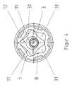
- FIG. 4 shows a section through the impeller 5 of the controllable coolant pump according to the invention according to FIG. 2 at B-B with the external rotor contour 8 arranged in the impeller 5 and the eccentric 11 arranged rotatably on the pump shaft 3.
- eccentric 11 On this eccentric 11 a rotatably provided with an external toothing inner rotor 12 is rotatably able to interact with the outer rotor contour 8 analogous to the operating principle of a gerotor.
- the filled with coolant displacement chambers 31 are formed, which can be "variably sealed” according to the invention by the pressure plate by means of the bimetallic disc and an effective control of the drive torque of the impeller 5 of the driven coolant pump with high efficiency, and so allow an optimal adjustment of the coolant flow rate to the heat balance of the engine.
- FIG. 5 now shows the controllable coolant pump according to the invention according to FIG. 2 with a pressure plate 13 pressed against the sealing collar 7 and sealing web 10 in hot coolant from the bimetallic disc 22 in accordance with the invention.
- this pressure plate 13 which is thus pressed, lies tight against the inner rotor 12 and thus prevents the fluid exchange between the two filled with coolant and formed by the outer rotor contour 8 and the outer toothing of the inner rotor 12 displacement chambers.
- the rotational speed of the impeller 5 approximately corresponds to the drive rotational speed of the pump shaft 3.
- FIG. 6 shows the controllable coolant pump according to the invention according to FIG. 2 with the pressure plate 13 completely relieved of the bimetallic disc 22.
- Coolant is pressed from one into the other displacement chamber via the opening gap between the sealing web 10, side wall of the inner rotor 12 and sealing collar 7, and the pressure plate 13 is displaced until it rests against the bimetal disk 22 again.
- the inner rotor 12 runs in the outer rotor contour 8 of the impeller 5.
- the gap width between the pressure plate 13, the sealing web 10, the side wall of the inner rotor 12 and the sealing collar 7 as a function of the coolant temperature exactly and smoothly steplessly controlled by means of the bimetallic disc 22.
- the solution according to the invention thus ensures an effective control of the drive torque of the impeller 5 of the driven coolant pump with high efficiency and thus an optimal adaptation of the coolant volume flow to the heat balance of the engine.
- a circulation groove 30 is arranged both in the bearing bore 28 of the impeller 5 and in the bearing seat 29 of the eccentric 11.
Landscapes
- Engineering & Computer Science (AREA)
- Mechanical Engineering (AREA)
- General Engineering & Computer Science (AREA)
- Chemical & Material Sciences (AREA)
- Combustion & Propulsion (AREA)
- Structures Of Non-Positive Displacement Pumps (AREA)
- Details And Applications Of Rotary Liquid Pumps (AREA)
- Sorption Type Refrigeration Machines (AREA)
- Particle Accelerators (AREA)
- Magnetic Resonance Imaging Apparatus (AREA)
Applications Claiming Priority (1)
| Application Number | Priority Date | Filing Date | Title |
|---|---|---|---|
| DE102005028598A DE102005028598B3 (de) | 2005-06-21 | 2005-06-21 | Regelbare Kühlmittelpumpe |
Publications (3)
| Publication Number | Publication Date |
|---|---|
| EP1736669A2 true EP1736669A2 (fr) | 2006-12-27 |
| EP1736669A3 EP1736669A3 (fr) | 2009-08-12 |
| EP1736669B1 EP1736669B1 (fr) | 2010-12-15 |
Family
ID=36997591
Family Applications (1)
| Application Number | Title | Priority Date | Filing Date |
|---|---|---|---|
| EP06010442A Not-in-force EP1736669B1 (fr) | 2005-06-21 | 2006-05-20 | Pompe de refroidissement réglable |
Country Status (3)
| Country | Link |
|---|---|
| EP (1) | EP1736669B1 (fr) |
| AT (1) | ATE491887T1 (fr) |
| DE (2) | DE102005028598B3 (fr) |
Cited By (3)
| Publication number | Priority date | Publication date | Assignee | Title |
|---|---|---|---|---|
| DE102010026132A1 (de) | 2010-07-05 | 2012-01-05 | Mahle International Gmbh | Laufrad und Fluidpumpe |
| WO2014023744A1 (fr) | 2012-08-07 | 2014-02-13 | Mahle International Gmbh | Dispositif de pompage |
| CN114165935A (zh) * | 2021-12-13 | 2022-03-11 | 恩德特机械(苏州)有限公司 | 一种基于智能化控制的螺杆式冷水机组 |
Families Citing this family (5)
| Publication number | Priority date | Publication date | Assignee | Title |
|---|---|---|---|---|
| DE102006048482A1 (de) * | 2006-10-11 | 2008-04-17 | Behr Gmbh & Co. Kg | Koppelungsvorrichtung für eine Kühlmittelpumpe, Verfahren zum Koppeln, Pumpe zum Kühlmittelpumpen |
| DE102010020118A1 (de) * | 2010-05-10 | 2011-11-10 | Mahle International Gmbh | Kupplungseinrichtung |
| IT1400958B1 (it) * | 2010-07-13 | 2013-07-05 | Ind Saleri Italo Spa | Pompa di raffreddamento con innesto. |
| DE102010032540B4 (de) * | 2010-07-28 | 2019-03-21 | Mahle International Gmbh | Kühlmittelpumpe |
| DE102011005108A1 (de) * | 2011-03-04 | 2012-09-06 | Mahle International Gmbh | Gleitringdichtung |
Family Cites Families (16)
| Publication number | Priority date | Publication date | Assignee | Title |
|---|---|---|---|---|
| DE2031508C3 (de) * | 1970-06-25 | 1973-10-04 | Fuerstlich Hohenzollernsche Huettenverwaltung Laucherthal, 7481 Laucherthal | Hydrostatische Kupplung |
| DE2616238A1 (de) * | 1976-04-13 | 1977-11-03 | Daimler Benz Ag | Kreiselpumpe |
| JPS5493760A (en) * | 1978-01-07 | 1979-07-25 | Toyota Motor Corp | Fluid coupling |
| DE3329002C2 (de) * | 1983-08-11 | 1985-08-22 | Daimler-Benz Ag, 7000 Stuttgart | Kühlmittelpumpe an einer Brennkraftmaschine für insbesondere Fahrzeuge |
| DE3611708A1 (de) * | 1986-04-08 | 1987-10-22 | Audi Ag | Kuehlmittelpumpe fuer eine fahrzeug-brennkraftmaschine |
| JP2942931B2 (ja) * | 1990-04-27 | 1999-08-30 | 臼井国際産業株式会社 | ベーンポンプ式フアンカツプリング装置 |
| DE4142120A1 (de) * | 1991-12-20 | 1993-06-24 | Porsche Ag | Kuehlwasserpumpe fuer eine brennkraftmaschine |
| JPH0622020A (ja) * | 1992-06-30 | 1994-01-28 | Toshiba Corp | 電話機 |
| DE4335340A1 (de) * | 1993-10-16 | 1995-04-20 | Behr Gmbh & Co | Antriebsvorrichtung für eine Wasserpumpe |
| DE4325627A1 (de) * | 1993-07-30 | 1995-02-02 | Behr Gmbh & Co | Antriebsvorrichtung für eine Wasserpumpe |
| DE19746359C2 (de) * | 1997-01-22 | 2003-02-06 | Eugen Schmidt | Regelbare Kühlmittelpumpe für Kraftfahrzeuge |
| DE19752372A1 (de) * | 1997-11-26 | 1999-05-27 | Guenther Dipl Ing Beez | Regelbare Kreiselpumpe, insbesondere für Verbrennungsmotore |
| DE19932359B4 (de) * | 1998-07-30 | 2007-05-16 | Behr Gmbh & Co Kg | Antrieb für eine Kühlmittelpumpe |
| JP2001342832A (ja) * | 2000-05-30 | 2001-12-14 | Honda Motor Co Ltd | エンジンのウオータポンプ駆動構造 |
| DE10142263C1 (de) * | 2001-08-29 | 2002-10-24 | Guenther Beez | Regelbare Kühlmittelpumpe |
| US6725813B1 (en) * | 2003-03-03 | 2004-04-27 | Borgwarner, Inc. | Temperature-controlled variable speed water pump |
-
2005
- 2005-06-21 DE DE102005028598A patent/DE102005028598B3/de not_active Expired - Fee Related
-
2006
- 2006-05-20 DE DE502006008492T patent/DE502006008492D1/de active Active
- 2006-05-20 EP EP06010442A patent/EP1736669B1/fr not_active Not-in-force
- 2006-05-20 AT AT06010442T patent/ATE491887T1/de active
Cited By (4)
| Publication number | Priority date | Publication date | Assignee | Title |
|---|---|---|---|---|
| DE102010026132A1 (de) | 2010-07-05 | 2012-01-05 | Mahle International Gmbh | Laufrad und Fluidpumpe |
| WO2014023744A1 (fr) | 2012-08-07 | 2014-02-13 | Mahle International Gmbh | Dispositif de pompage |
| DE102012213985A1 (de) | 2012-08-07 | 2014-02-13 | Mahle International Gmbh | Pumpeneinrichtung |
| CN114165935A (zh) * | 2021-12-13 | 2022-03-11 | 恩德特机械(苏州)有限公司 | 一种基于智能化控制的螺杆式冷水机组 |
Also Published As
| Publication number | Publication date |
|---|---|
| DE102005028598B3 (de) | 2006-10-05 |
| ATE491887T1 (de) | 2011-01-15 |
| EP1736669A3 (fr) | 2009-08-12 |
| DE502006008492D1 (de) | 2011-01-27 |
| EP1736669B1 (fr) | 2010-12-15 |
Similar Documents
| Publication | Publication Date | Title |
|---|---|---|
| DE69911824T2 (de) | Wassergekühlter Flüssigkeitsreibungsantrieb eines Ventilators | |
| EP0855515B1 (fr) | Pompe de refroidissement réglable pour véhicules | |
| DE102005004315B4 (de) | Regelbare Kühlmittelpumpe | |
| DE3211337C2 (de) | Hydrodynamische Regelkupplung | |
| DE19746359C2 (de) | Regelbare Kühlmittelpumpe für Kraftfahrzeuge | |
| DE3927153C2 (de) | Temperaturgesteuerte Ventilatorflüssigkeitsreibungskupplung | |
| DE69800206T2 (de) | Hochbelastbarer viskose Ventilatorantrieb sowie Haltevorrichtung dafür | |
| DE69723060T2 (de) | Kühlmittelpumpe zur kraftfahrzeugverwendung | |
| EP1391624A1 (fr) | Embrayage à frottement visqueux | |
| DE112011102058B4 (de) | Innenzahnrad-Ölpumpe für ein Fahrzeug | |
| EP1736669B1 (fr) | Pompe de refroidissement réglable | |
| EP1731787B1 (fr) | Accouplement à fluide visqueux | |
| DE3329002C2 (de) | Kühlmittelpumpe an einer Brennkraftmaschine für insbesondere Fahrzeuge | |
| DE2848514C2 (de) | Pumpenanordnung | |
| DE10355499B4 (de) | Wasserpumpe und Verfahren zum Steuern der Durchflussrate von Kühlmittel | |
| EP2406498B1 (fr) | Pompe de liquide de refroidissement à régulation | |
| DE2439256A1 (de) | Viskositaetskupplung | |
| DE10142263C1 (de) | Regelbare Kühlmittelpumpe | |
| DE3714086A1 (de) | Fluessigkeitsreibungskupplung | |
| DE102016116636B4 (de) | Kühlmittelpumpe für den Kfz-Bereich sowie ein Kühlmittelkreislauf für eine Verbrennungskraftmaschine | |
| DE69030676T2 (de) | Viskose Flüssigkeitsreibungskupplung und Regelventile dafür | |
| DE2103598C3 (de) | Hydrodynamische Kupplung | |
| EP0641947A2 (fr) | Dispositif d'entraînement pour une pompe à l'eau | |
| EP3077676A1 (fr) | Pompe réglable pour moteur à combustion interne | |
| EP2486282B1 (fr) | Pompe de fluide de refroidissement |
Legal Events
| Date | Code | Title | Description |
|---|---|---|---|
| PUAI | Public reference made under article 153(3) epc to a published international application that has entered the european phase |
Free format text: ORIGINAL CODE: 0009012 |
|
| AK | Designated contracting states |
Kind code of ref document: A2 Designated state(s): AT BE BG CH CY CZ DE DK EE ES FI FR GB GR HU IE IS IT LI LT LU LV MC NL PL PT RO SE SI SK TR |
|
| AX | Request for extension of the european patent |
Extension state: AL BA HR MK YU |
|
| PUAL | Search report despatched |
Free format text: ORIGINAL CODE: 0009013 |
|
| AK | Designated contracting states |
Kind code of ref document: A3 Designated state(s): AT BE BG CH CY CZ DE DK EE ES FI FR GB GR HU IE IS IT LI LT LU LV MC NL PL PT RO SE SI SK TR |
|
| AX | Request for extension of the european patent |
Extension state: AL BA HR MK YU |
|
| RIC1 | Information provided on ipc code assigned before grant |
Ipc: F01P 7/16 20060101ALI20090709BHEP Ipc: F04D 15/00 20060101AFI20060926BHEP |
|
| RAP1 | Party data changed (applicant data changed or rights of an application transferred) |
Owner name: MAHLE INTERNATIONAL GMBH |
|
| 17P | Request for examination filed |
Effective date: 20091219 |
|
| AKX | Designation fees paid |
Designated state(s): AT BE BG CH CY CZ DE DK EE ES FI FR GB GR HU IE IS IT LI LT LU LV MC NL PL PT RO SE SI SK TR |
|
| GRAP | Despatch of communication of intention to grant a patent |
Free format text: ORIGINAL CODE: EPIDOSNIGR1 |
|
| GRAS | Grant fee paid |
Free format text: ORIGINAL CODE: EPIDOSNIGR3 |
|
| GRAA | (expected) grant |
Free format text: ORIGINAL CODE: 0009210 |
|
| AK | Designated contracting states |
Kind code of ref document: B1 Designated state(s): AT BE BG CH CY CZ DE DK EE ES FI FR GB GR HU IE IS IT LI LT LU LV MC NL PL PT RO SE SI SK TR |
|
| REG | Reference to a national code |
Ref country code: CH Ref legal event code: EP Ref country code: GB Ref legal event code: FG4D Free format text: NOT ENGLISH |
|
| REG | Reference to a national code |
Ref country code: IE Ref legal event code: FG4D |
|
| REF | Corresponds to: |
Ref document number: 502006008492 Country of ref document: DE Date of ref document: 20110127 Kind code of ref document: P |
|
| REG | Reference to a national code |
Ref country code: NL Ref legal event code: VDEP Effective date: 20101215 |
|
| PG25 | Lapsed in a contracting state [announced via postgrant information from national office to epo] |
Ref country code: LT Free format text: LAPSE BECAUSE OF FAILURE TO SUBMIT A TRANSLATION OF THE DESCRIPTION OR TO PAY THE FEE WITHIN THE PRESCRIBED TIME-LIMIT Effective date: 20101215 |
|
| LTIE | Lt: invalidation of european patent or patent extension |
Effective date: 20101215 |
|
| PG25 | Lapsed in a contracting state [announced via postgrant information from national office to epo] |
Ref country code: FI Free format text: LAPSE BECAUSE OF FAILURE TO SUBMIT A TRANSLATION OF THE DESCRIPTION OR TO PAY THE FEE WITHIN THE PRESCRIBED TIME-LIMIT Effective date: 20101215 Ref country code: BG Free format text: LAPSE BECAUSE OF FAILURE TO SUBMIT A TRANSLATION OF THE DESCRIPTION OR TO PAY THE FEE WITHIN THE PRESCRIBED TIME-LIMIT Effective date: 20110315 Ref country code: SI Free format text: LAPSE BECAUSE OF FAILURE TO SUBMIT A TRANSLATION OF THE DESCRIPTION OR TO PAY THE FEE WITHIN THE PRESCRIBED TIME-LIMIT Effective date: 20101215 Ref country code: CY Free format text: LAPSE BECAUSE OF FAILURE TO SUBMIT A TRANSLATION OF THE DESCRIPTION OR TO PAY THE FEE WITHIN THE PRESCRIBED TIME-LIMIT Effective date: 20101215 Ref country code: LV Free format text: LAPSE BECAUSE OF FAILURE TO SUBMIT A TRANSLATION OF THE DESCRIPTION OR TO PAY THE FEE WITHIN THE PRESCRIBED TIME-LIMIT Effective date: 20101215 Ref country code: NL Free format text: LAPSE BECAUSE OF FAILURE TO SUBMIT A TRANSLATION OF THE DESCRIPTION OR TO PAY THE FEE WITHIN THE PRESCRIBED TIME-LIMIT Effective date: 20101215 Ref country code: SE Free format text: LAPSE BECAUSE OF FAILURE TO SUBMIT A TRANSLATION OF THE DESCRIPTION OR TO PAY THE FEE WITHIN THE PRESCRIBED TIME-LIMIT Effective date: 20101215 |
|
| REG | Reference to a national code |
Ref country code: IE Ref legal event code: FD4D |
|
| PG25 | Lapsed in a contracting state [announced via postgrant information from national office to epo] |
Ref country code: CZ Free format text: LAPSE BECAUSE OF FAILURE TO SUBMIT A TRANSLATION OF THE DESCRIPTION OR TO PAY THE FEE WITHIN THE PRESCRIBED TIME-LIMIT Effective date: 20101215 Ref country code: IS Free format text: LAPSE BECAUSE OF FAILURE TO SUBMIT A TRANSLATION OF THE DESCRIPTION OR TO PAY THE FEE WITHIN THE PRESCRIBED TIME-LIMIT Effective date: 20110415 Ref country code: EE Free format text: LAPSE BECAUSE OF FAILURE TO SUBMIT A TRANSLATION OF THE DESCRIPTION OR TO PAY THE FEE WITHIN THE PRESCRIBED TIME-LIMIT Effective date: 20101215 Ref country code: IE Free format text: LAPSE BECAUSE OF FAILURE TO SUBMIT A TRANSLATION OF THE DESCRIPTION OR TO PAY THE FEE WITHIN THE PRESCRIBED TIME-LIMIT Effective date: 20101215 Ref country code: ES Free format text: LAPSE BECAUSE OF FAILURE TO SUBMIT A TRANSLATION OF THE DESCRIPTION OR TO PAY THE FEE WITHIN THE PRESCRIBED TIME-LIMIT Effective date: 20110326 Ref country code: PT Free format text: LAPSE BECAUSE OF FAILURE TO SUBMIT A TRANSLATION OF THE DESCRIPTION OR TO PAY THE FEE WITHIN THE PRESCRIBED TIME-LIMIT Effective date: 20110415 Ref country code: GR Free format text: LAPSE BECAUSE OF FAILURE TO SUBMIT A TRANSLATION OF THE DESCRIPTION OR TO PAY THE FEE WITHIN THE PRESCRIBED TIME-LIMIT Effective date: 20110316 |
|
| PG25 | Lapsed in a contracting state [announced via postgrant information from national office to epo] |
Ref country code: RO Free format text: LAPSE BECAUSE OF FAILURE TO SUBMIT A TRANSLATION OF THE DESCRIPTION OR TO PAY THE FEE WITHIN THE PRESCRIBED TIME-LIMIT Effective date: 20101215 Ref country code: SK Free format text: LAPSE BECAUSE OF FAILURE TO SUBMIT A TRANSLATION OF THE DESCRIPTION OR TO PAY THE FEE WITHIN THE PRESCRIBED TIME-LIMIT Effective date: 20101215 Ref country code: PL Free format text: LAPSE BECAUSE OF FAILURE TO SUBMIT A TRANSLATION OF THE DESCRIPTION OR TO PAY THE FEE WITHIN THE PRESCRIBED TIME-LIMIT Effective date: 20101215 |
|
| PLBE | No opposition filed within time limit |
Free format text: ORIGINAL CODE: 0009261 |
|
| STAA | Information on the status of an ep patent application or granted ep patent |
Free format text: STATUS: NO OPPOSITION FILED WITHIN TIME LIMIT |
|
| PG25 | Lapsed in a contracting state [announced via postgrant information from national office to epo] |
Ref country code: DK Free format text: LAPSE BECAUSE OF FAILURE TO SUBMIT A TRANSLATION OF THE DESCRIPTION OR TO PAY THE FEE WITHIN THE PRESCRIBED TIME-LIMIT Effective date: 20101215 |
|
| 26N | No opposition filed |
Effective date: 20110916 |
|
| BERE | Be: lapsed |
Owner name: MAHLE INTERNATIONAL G.M.B.H. Effective date: 20110531 |
|
| PG25 | Lapsed in a contracting state [announced via postgrant information from national office to epo] |
Ref country code: MC Free format text: LAPSE BECAUSE OF NON-PAYMENT OF DUE FEES Effective date: 20110531 |
|
| REG | Reference to a national code |
Ref country code: CH Ref legal event code: PL |
|
| REG | Reference to a national code |
Ref country code: DE Ref legal event code: R097 Ref document number: 502006008492 Country of ref document: DE Effective date: 20110916 |
|
| PG25 | Lapsed in a contracting state [announced via postgrant information from national office to epo] |
Ref country code: CH Free format text: LAPSE BECAUSE OF NON-PAYMENT OF DUE FEES Effective date: 20110531 Ref country code: LI Free format text: LAPSE BECAUSE OF NON-PAYMENT OF DUE FEES Effective date: 20110531 |
|
| PG25 | Lapsed in a contracting state [announced via postgrant information from national office to epo] |
Ref country code: BE Free format text: LAPSE BECAUSE OF NON-PAYMENT OF DUE FEES Effective date: 20110531 |
|
| REG | Reference to a national code |
Ref country code: AT Ref legal event code: MM01 Ref document number: 491887 Country of ref document: AT Kind code of ref document: T Effective date: 20110520 |
|
| PG25 | Lapsed in a contracting state [announced via postgrant information from national office to epo] |
Ref country code: AT Free format text: LAPSE BECAUSE OF NON-PAYMENT OF DUE FEES Effective date: 20110520 |
|
| PG25 | Lapsed in a contracting state [announced via postgrant information from national office to epo] |
Ref country code: LU Free format text: LAPSE BECAUSE OF NON-PAYMENT OF DUE FEES Effective date: 20110520 |
|
| PG25 | Lapsed in a contracting state [announced via postgrant information from national office to epo] |
Ref country code: TR Free format text: LAPSE BECAUSE OF FAILURE TO SUBMIT A TRANSLATION OF THE DESCRIPTION OR TO PAY THE FEE WITHIN THE PRESCRIBED TIME-LIMIT Effective date: 20101215 |
|
| PG25 | Lapsed in a contracting state [announced via postgrant information from national office to epo] |
Ref country code: HU Free format text: LAPSE BECAUSE OF FAILURE TO SUBMIT A TRANSLATION OF THE DESCRIPTION OR TO PAY THE FEE WITHIN THE PRESCRIBED TIME-LIMIT Effective date: 20101215 |
|
| REG | Reference to a national code |
Ref country code: FR Ref legal event code: PLFP Year of fee payment: 11 |
|
| REG | Reference to a national code |
Ref country code: FR Ref legal event code: PLFP Year of fee payment: 12 |
|
| REG | Reference to a national code |
Ref country code: FR Ref legal event code: PLFP Year of fee payment: 13 |
|
| PGFP | Annual fee paid to national office [announced via postgrant information from national office to epo] |
Ref country code: IT Payment date: 20190524 Year of fee payment: 14 |
|
| PGFP | Annual fee paid to national office [announced via postgrant information from national office to epo] |
Ref country code: FR Payment date: 20190528 Year of fee payment: 14 |
|
| PGFP | Annual fee paid to national office [announced via postgrant information from national office to epo] |
Ref country code: DE Payment date: 20190731 Year of fee payment: 14 Ref country code: GB Payment date: 20190529 Year of fee payment: 14 |
|
| REG | Reference to a national code |
Ref country code: DE Ref legal event code: R119 Ref document number: 502006008492 Country of ref document: DE |
|
| GBPC | Gb: european patent ceased through non-payment of renewal fee |
Effective date: 20200520 |
|
| PG25 | Lapsed in a contracting state [announced via postgrant information from national office to epo] |
Ref country code: GB Free format text: LAPSE BECAUSE OF NON-PAYMENT OF DUE FEES Effective date: 20200520 Ref country code: FR Free format text: LAPSE BECAUSE OF NON-PAYMENT OF DUE FEES Effective date: 20200531 |
|
| PG25 | Lapsed in a contracting state [announced via postgrant information from national office to epo] |
Ref country code: DE Free format text: LAPSE BECAUSE OF NON-PAYMENT OF DUE FEES Effective date: 20201201 |
|
| PG25 | Lapsed in a contracting state [announced via postgrant information from national office to epo] |
Ref country code: IT Free format text: LAPSE BECAUSE OF NON-PAYMENT OF DUE FEES Effective date: 20200520 |