EP1736744B1 - Capteur de niveau de remplissage - Google Patents
Capteur de niveau de remplissage Download PDFInfo
- Publication number
- EP1736744B1 EP1736744B1 EP06114611.4A EP06114611A EP1736744B1 EP 1736744 B1 EP1736744 B1 EP 1736744B1 EP 06114611 A EP06114611 A EP 06114611A EP 1736744 B1 EP1736744 B1 EP 1736744B1
- Authority
- EP
- European Patent Office
- Prior art keywords
- edge
- level sensor
- filling level
- cover
- mounting plate
- Prior art date
- Legal status (The legal status is an assumption and is not a legal conclusion. Google has not performed a legal analysis and makes no representation as to the accuracy of the status listed.)
- Ceased
Links
Images

Classifications
-
- G—PHYSICS
- G01—MEASURING; TESTING
- G01F—MEASURING VOLUME, VOLUME FLOW, MASS FLOW OR LIQUID LEVEL; METERING BY VOLUME
- G01F23/00—Indicating or measuring liquid level or level of fluent solid material, e.g. indicating in terms of volume or indicating by means of an alarm
- G01F23/30—Indicating or measuring liquid level or level of fluent solid material, e.g. indicating in terms of volume or indicating by means of an alarm by floats
- G01F23/32—Indicating or measuring liquid level or level of fluent solid material, e.g. indicating in terms of volume or indicating by means of an alarm by floats using rotatable arms or other pivotable transmission elements
- G01F23/36—Indicating or measuring liquid level or level of fluent solid material, e.g. indicating in terms of volume or indicating by means of an alarm by floats using rotatable arms or other pivotable transmission elements using electrically actuated indicating means
- G01F23/363—Indicating or measuring liquid level or level of fluent solid material, e.g. indicating in terms of volume or indicating by means of an alarm by floats using rotatable arms or other pivotable transmission elements using electrically actuated indicating means using electromechanically actuated indicating means
Definitions
- the invention relates to a level sensor for a fuel tank, consisting of a ceramic support plate having a resistor network arranged thereon and a contact structure for determining an electrical signal for the level and a lid connected to the carrier plate, wherein the lid and the carrier plate form a housing.
- the housing of such sensors serves to accommodate various components of the sensor to protect against aggressive media.
- the housing When using the sensor in a fuel tank, the housing must be primarily fuel-resistant and liquid-tight.
- a thin-walled lid made of metal which in addition to the liquid-tight construction of the housing at the same time sufficient protection against the pressures occurring in the operation of the fuel tank in the range of 70-100 mbar is dimensionally stable.
- the publication DE 29700625 U1 discloses a level sensor for the tank of a motor vehicle, which should allow a favorable manufacturability and high accuracy.
- the level sensor in this case comprises a resistor network which is arranged on a fixed carrier, wherein the resistor network according to the position of the level of a liquid following float an output signal is removable.
- the level sensor is not introduced in the finished fuel tank, but previously in a plastic container forming the subsequent fuel tank, the level sensor can be exposed during the manufacturing process of the fuel tank much higher pressures in the range of 8 bar to 12 bar. As a result of these high pressures, there is deformation of the lid and the carrier plate, which in turn lead to breakage of the support plate, whereby the tightness of the housing is no longer guaranteed.
- the invention is therefore an object of the invention to provide a level sensor, which is resistant in addition to the resistance to the influences of its place of use against a pre-assembly with difficult environmental influences.
- the object is achieved in that the lid is reinforced in its edge region by means of a separate element metallic.
- the reinforcement of the lid With the reinforcement of the lid in its edge region, a mechanical reinforcement of the housing and thus a greater resistance of the cover is achieved against deformation in a particularly simple manner, which in turn results in that the support plate is mounted more firmly, thereby acting even with larger on the housing Press less deformed and thus not damaged and the tightness of the housing is maintained. Since the gain is based only on the lid, remaining components of the level sensor can continue to be used unchanged. However, the reinforcement of the lid not only provides protection at high pressures, but also at very low pressures compared to normal pressure.
- the metallic reinforcement of the edge region is achieved by a metal frame applied on the side of the edge facing away from the carrier plate, which forms the separate element.
- This embodiment has the advantage that only one additional component is to be provided with the metal frame in order to achieve the desired reinforcement.
- a reinforcement of the lid of level sensors of different dimensions is achieved in a simple manner, when arranged on the side facing away from the carrier plate edge along the side surfaces metal strips.
- the advantage is that the metal strips can be adapted to different dimensions of the lid with little effort.
- the metal strips can have both a rectangular and a round cross-section.
- the metal strips along two side surfaces, preferably in longitudinal alignment, are arranged on the edge.
- fillet welds for increasing the mechanical rigidity are applied in the regions formed by the side surfaces and the edge of the lid.
- the fillet welds can be arranged along all side surfaces or along selected side surfaces.
- the effort to arrange the fillet welds is low when the fillet welds are applied by soldering.
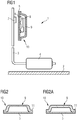
- the in FIG. 1 shown level sensor 1 is arranged in a fuel tank 2.
- the level sensor 1 consists of a pivotally mounted lever arm 3, at one end of a float 4 is mounted.
- the level sensor 1 further has a ceramic carrier plate 5, on which an electrical resistance network 6 is applied.
- a deflectable by the lever arm 3 by means of a magnet 7 contact structure 8 generates a function of the Hebelarm ein electrical signal for the level.
- the support plate 5 is connected to a cover 9 to form a housing 10 such that the resistance network 6 and the contact structure 8 are sealed from the environment.
- FIG. 2 shows the existing cover 9 and support plate 5 housing 10 of the level sensor 1.
- the edge 11 has 0.8 mm a greater wall thickness than the upper, planar portion of the lid 9, which has a wall thickness of 0.4 mm. As a result, the lid 9 is given a sufficient mechanical reinforcement.
- FIG. 2a shows a further embodiment of the level sensor 1, which faces FIG. 2 differs in that the cover 9 has a constant wall thickness of 0.8 mm, while the support plate 5 has a thickness of about 0.6 mm.
- cover 9 has to reinforce a metal frame 12 which is disposed on the side facing away from the carrier plate of the edge 11 by means of soldering.
- FIGS. 4 and 5 are to reinforce the lid 9 metal strip 13 on the side facing away from the carrier plate of the Edge 11 soldered.
- the metal strips have a rectangular and round cross-section. In the illustrations shown, the metal strips 13 are arranged parallel to the longest extent of the lid 9.
- the mechanical reinforcement is achieved by fillets 14 which are arranged in the areas formed by the side surfaces 15 and the edge 11 of the lid 9, wherein the fillet welds 14 are also arranged only in the areas which are parallel to the longest extent of the lid 9 are lost.
Landscapes
- Physics & Mathematics (AREA)
- Fluid Mechanics (AREA)
- General Physics & Mathematics (AREA)
- Level Indicators Using A Float (AREA)
- Measurement Of Levels Of Liquids Or Fluent Solid Materials (AREA)
- Cooling, Air Intake And Gas Exhaust, And Fuel Tank Arrangements In Propulsion Units (AREA)
Claims (6)
- Capteur de niveau de remplissage (1) destiné à un réservoir de carburant (2), constitué d'une plaque de support en céramique (5) pourvue d'un réseau de résistances (6) disposé sur celle-ci et d'une structure de contact (8) destinée à déterminer un signal électrique pour le niveau de remplissage, et d'un couvercle (9) en forme de pot relié à la plaque de support (5), qui présente un bord périphérique (11) dirigé vers l'extérieur et des surfaces latérales (15) adjacentes à celui-ci, dans lequel le couvercle (9) et la plaque de support (5) forment un boîtier fermé (10) en raison du fait que le bord (11) du couvercle (9) repose sur la plaque support (5), dans lequel le couvercle (9) possède une zone de bord formée par le bord (11) et les surfaces latérales adjacentes (15),
caractérisé en ce que le couvercle (9) est renforcé métalliquement le long d'au moins une surface latérale (15) dans sa zone de bord au moyen d'un élément séparé (12, 13, 14). - Capteur de niveau de remplissage (1) selon la revendication 1, caractérisé en ce que l'élément séparé est réalisé sous la forme d'un châssis métallique (12) qui est réalisé sur le côté du bord (11) qui est tourné à l'opposé de la plaque de support (5).
- Capteur de niveau de remplissage (1) selon la revendication 1, caractérisé en ce que l'élément séparé est réalisé sous la forme de bandes métalliques (13) qui sont disposées le long des faces latérales (15) sur le côté du bord (11) qui est tourné à l'opposé de la plaque de support (5).
- Capteur de niveau de remplissage (1) selon la revendication 3, caractérisé en ce que les bandes métalliques (13) sont disposées le long de deux surfaces latérales (15) sur le bord (11), de préférence de manière orientée longitudinalement.
- Capteur de niveau de remplissage (1) selon la revendication 1, caractérisé en ce que l'élément séparé est réalisé sous la forme de soudures d'angle (14) qui sont réalisées dans les zones formées par les faces latérales (15) et le bord (11) du couvercle (9).
- Capteur de niveau (1) selon la revendication 5, caractérisé en ce que les soudures d'angle (14) sont réalisées par brasage.
Applications Claiming Priority (1)
| Application Number | Priority Date | Filing Date | Title |
|---|---|---|---|
| DE102005029785A DE102005029785B4 (de) | 2005-06-24 | 2005-06-24 | Füllstandsensor |
Publications (3)
| Publication Number | Publication Date |
|---|---|
| EP1736744A2 EP1736744A2 (fr) | 2006-12-27 |
| EP1736744A3 EP1736744A3 (fr) | 2007-02-21 |
| EP1736744B1 true EP1736744B1 (fr) | 2019-08-14 |
Family
ID=37023014
Family Applications (1)
| Application Number | Title | Priority Date | Filing Date |
|---|---|---|---|
| EP06114611.4A Ceased EP1736744B1 (fr) | 2005-06-24 | 2006-05-29 | Capteur de niveau de remplissage |
Country Status (3)
| Country | Link |
|---|---|
| US (1) | US7513153B2 (fr) |
| EP (1) | EP1736744B1 (fr) |
| DE (1) | DE102005029785B4 (fr) |
Families Citing this family (4)
| Publication number | Priority date | Publication date | Assignee | Title |
|---|---|---|---|---|
| DE102011088949C5 (de) * | 2011-12-19 | 2022-02-24 | Vitesco Technologies GmbH | Füllstandsgeber |
| DE102012200054A1 (de) | 2012-01-03 | 2013-07-04 | Continental Automotive Gmbh | Ventilvorrichtung für ein Kraftfahrzeug |
| DE102016213501A1 (de) * | 2016-07-22 | 2018-01-25 | Continental Automotive Gmbh | Füllstandsgeber |
| DE102016213514A1 (de) * | 2016-07-22 | 2018-01-25 | Continental Automotive Gmbh | Passiver magnetischer Positionssensor |
Citations (3)
| Publication number | Priority date | Publication date | Assignee | Title |
|---|---|---|---|---|
| US3913400A (en) * | 1974-04-10 | 1975-10-21 | Mueller Co | Plastic meter box |
| DE29700625U1 (de) * | 1997-01-16 | 1997-03-13 | VDO Adolf Schindling AG, 60326 Frankfurt | Füllstandsgeber |
| US6749080B1 (en) * | 2003-03-05 | 2004-06-15 | White Kennith R | Underground utility housing |
Family Cites Families (7)
| Publication number | Priority date | Publication date | Assignee | Title |
|---|---|---|---|---|
| US3403376A (en) * | 1964-11-12 | 1968-09-24 | Stewart Warner Corp | Fuel depletion alarm circuit utilizing bimetal |
| US3756080A (en) * | 1970-05-11 | 1973-09-04 | Pringle W And Associates Inc | Fuel tank assembly |
| US5357815A (en) * | 1993-02-10 | 1994-10-25 | Rochester Gauges, Inc. | Magnetically driven gauge with voltage divider |
| JPH08330703A (ja) * | 1995-05-30 | 1996-12-13 | Nec Gumma Ltd | 表面実装部品 |
| AU3583895A (en) * | 1995-06-07 | 1996-12-30 | Rochester Gauges, Inc. | Liquid level gauge assembly including potentiometer with con ductive polymeric element |
| DE19701246A1 (de) * | 1997-01-16 | 1998-07-23 | Mannesmann Vdo Ag | Füllstandsgeber |
| US5992679A (en) * | 1998-06-25 | 1999-11-30 | S. C. Johnson Home Storage, Inc. | Container Having a selectively detachable lid including an interrupted reinforcing bead |
-
2005
- 2005-06-24 DE DE102005029785A patent/DE102005029785B4/de not_active Expired - Fee Related
-
2006
- 2006-05-29 EP EP06114611.4A patent/EP1736744B1/fr not_active Ceased
- 2006-06-21 US US11/473,287 patent/US7513153B2/en active Active
Patent Citations (3)
| Publication number | Priority date | Publication date | Assignee | Title |
|---|---|---|---|---|
| US3913400A (en) * | 1974-04-10 | 1975-10-21 | Mueller Co | Plastic meter box |
| DE29700625U1 (de) * | 1997-01-16 | 1997-03-13 | VDO Adolf Schindling AG, 60326 Frankfurt | Füllstandsgeber |
| US6749080B1 (en) * | 2003-03-05 | 2004-06-15 | White Kennith R | Underground utility housing |
Also Published As
| Publication number | Publication date |
|---|---|
| EP1736744A2 (fr) | 2006-12-27 |
| US20070006647A1 (en) | 2007-01-11 |
| DE102005029785B4 (de) | 2009-04-16 |
| EP1736744A3 (fr) | 2007-02-21 |
| US7513153B2 (en) | 2009-04-07 |
| DE102005029785A1 (de) | 2007-01-11 |
Similar Documents
| Publication | Publication Date | Title |
|---|---|---|
| DE112008003218B4 (de) | Piezoelektrische Schwingungskomponente | |
| DE102004022570B4 (de) | Abgedichteter Kraftstoffstandsensor | |
| DE4436158C2 (de) | Piezoelektrischer Summer | |
| EP2373958A1 (fr) | Dispositif de mesure de la conductivité et dispositif de traitement de liquides | |
| DE10341482B4 (de) | Gehäuselose Wägezelle | |
| DE102005029785B4 (de) | Füllstandsensor | |
| DE102014215047A1 (de) | Gehäuse mit einer Öffnung und einer Abdeckeinrichtung | |
| DE3150435C2 (fr) | ||
| DE102008064019A1 (de) | Füllstandssensor | |
| EP1736743B1 (fr) | Capteur de niveau de remplissage | |
| EP1726753B1 (fr) | Poignée de porte pour véhicule automobile avec un capteur de proximité capacitive | |
| WO2015055579A1 (fr) | Capteur de niveau | |
| DE69504898T2 (de) | Kraftstoffabsaug- und Anzeigevorrichtung eines Fahrzeuges | |
| WO2000002431A2 (fr) | Boitier pour unite electronique, notamment pour appareil de commande d'airbag | |
| WO2009046966A1 (fr) | Détecteur de pluie capacitif équipé d'une surface sensible agrandie | |
| DE2445805C3 (de) | Verfahren zur Herstellung einer mit bestimmungsgemäß gerichteter, vom Finger ausgeübter Druckkraft zu betätigenden Taste | |
| DE102005029786B4 (de) | Füllstandsensor | |
| DE102004010912C5 (de) | Messsonde zur Bestimmung von physikalischen Parametern an oder in einem Kessel | |
| DE2433208C3 (de) | Verbesserung einer piezoelektrischen Taste | |
| DE2515388C3 (de) | Wischvorrichtung für Scheiben von Fahrzeugen, insbesondere Kraftfahrzeugen | |
| DE29700625U1 (de) | Füllstandsgeber | |
| EP2477014B1 (fr) | Indicateur de niveau de remplissage | |
| DE102005040219B4 (de) | Bauteil mit umgebogenem Seitenelement | |
| DE10332641B3 (de) | Anzeigevorrichtung, insbesondere für eine Bedieneinheit in z.B. einem Fahrzeug, insbesondere Kraftfahrzeug | |
| DE102013214687B4 (de) | Drucksensor |
Legal Events
| Date | Code | Title | Description |
|---|---|---|---|
| PUAI | Public reference made under article 153(3) epc to a published international application that has entered the european phase |
Free format text: ORIGINAL CODE: 0009012 |
|
| AK | Designated contracting states |
Kind code of ref document: A2 Designated state(s): AT BE BG CH CY CZ DE DK EE ES FI FR GB GR HU IE IS IT LI LT LU LV MC NL PL PT RO SE SI SK TR |
|
| AX | Request for extension of the european patent |
Extension state: AL BA HR MK YU |
|
| PUAL | Search report despatched |
Free format text: ORIGINAL CODE: 0009013 |
|
| AK | Designated contracting states |
Kind code of ref document: A3 Designated state(s): AT BE BG CH CY CZ DE DK EE ES FI FR GB GR HU IE IS IT LI LT LU LV MC NL PL PT RO SE SI SK TR |
|
| AX | Request for extension of the european patent |
Extension state: AL BA HR MK YU |
|
| 17P | Request for examination filed |
Effective date: 20070205 |
|
| 17Q | First examination report despatched |
Effective date: 20070403 |
|
| AKX | Designation fees paid |
Designated state(s): DE ES FR GB IT |
|
| RAP1 | Party data changed (applicant data changed or rights of an application transferred) |
Owner name: CONTINENTAL AUTOMOTIVE GMBH |
|
| STAA | Information on the status of an ep patent application or granted ep patent |
Free format text: STATUS: EXAMINATION IS IN PROGRESS |
|
| GRAP | Despatch of communication of intention to grant a patent |
Free format text: ORIGINAL CODE: EPIDOSNIGR1 |
|
| STAA | Information on the status of an ep patent application or granted ep patent |
Free format text: STATUS: GRANT OF PATENT IS INTENDED |
|
| INTG | Intention to grant announced |
Effective date: 20190125 |
|
| GRAS | Grant fee paid |
Free format text: ORIGINAL CODE: EPIDOSNIGR3 |
|
| RAP1 | Party data changed (applicant data changed or rights of an application transferred) |
Owner name: CPT GROUP GMBH |
|
| GRAA | (expected) grant |
Free format text: ORIGINAL CODE: 0009210 |
|
| STAA | Information on the status of an ep patent application or granted ep patent |
Free format text: STATUS: THE PATENT HAS BEEN GRANTED |
|
| REG | Reference to a national code |
Ref country code: DE Ref legal event code: R081 Ref document number: 502006016328 Country of ref document: DE Owner name: VITESCO TECHNOLOGIES GMBH, DE Free format text: FORMER OWNER: SIEMENS AKTIENGESELLSCHAFT, 80333 MUENCHEN, DE |
|
| AK | Designated contracting states |
Kind code of ref document: B1 Designated state(s): DE ES FR GB IT |
|
| REG | Reference to a national code |
Ref country code: GB Ref legal event code: FG4D Free format text: NOT ENGLISH |
|
| REG | Reference to a national code |
Ref country code: DE Ref legal event code: R096 Ref document number: 502006016328 Country of ref document: DE |
|
| RAP2 | Party data changed (patent owner data changed or rights of a patent transferred) |
Owner name: VITESCO TECHNOLOGIES GMBH |
|
| REG | Reference to a national code |
Ref country code: DE Ref legal event code: R081 Ref document number: 502006016328 Country of ref document: DE Owner name: VITESCO TECHNOLOGIES GMBH, DE Free format text: FORMER OWNER: CPT GROUP GMBH, 30165 HANNOVER, DE |
|
| PG25 | Lapsed in a contracting state [announced via postgrant information from national office to epo] |
Ref country code: ES Free format text: LAPSE BECAUSE OF FAILURE TO SUBMIT A TRANSLATION OF THE DESCRIPTION OR TO PAY THE FEE WITHIN THE PRESCRIBED TIME-LIMIT Effective date: 20190814 |
|
| PG25 | Lapsed in a contracting state [announced via postgrant information from national office to epo] |
Ref country code: IT Free format text: LAPSE BECAUSE OF FAILURE TO SUBMIT A TRANSLATION OF THE DESCRIPTION OR TO PAY THE FEE WITHIN THE PRESCRIBED TIME-LIMIT Effective date: 20190814 |
|
| REG | Reference to a national code |
Ref country code: DE Ref legal event code: R097 Ref document number: 502006016328 Country of ref document: DE |
|
| PLBE | No opposition filed within time limit |
Free format text: ORIGINAL CODE: 0009261 |
|
| STAA | Information on the status of an ep patent application or granted ep patent |
Free format text: STATUS: NO OPPOSITION FILED WITHIN TIME LIMIT |
|
| PGFP | Annual fee paid to national office [announced via postgrant information from national office to epo] |
Ref country code: DE Payment date: 20200531 Year of fee payment: 15 |
|
| 26N | No opposition filed |
Effective date: 20200603 |
|
| GBPC | Gb: european patent ceased through non-payment of renewal fee |
Effective date: 20200529 |
|
| PG25 | Lapsed in a contracting state [announced via postgrant information from national office to epo] |
Ref country code: GB Free format text: LAPSE BECAUSE OF NON-PAYMENT OF DUE FEES Effective date: 20200529 |
|
| PGFP | Annual fee paid to national office [announced via postgrant information from national office to epo] |
Ref country code: FR Payment date: 20210520 Year of fee payment: 16 |
|
| REG | Reference to a national code |
Ref country code: DE Ref legal event code: R119 Ref document number: 502006016328 Country of ref document: DE |
|
| REG | Reference to a national code |
Ref country code: DE Ref legal event code: R081 Ref document number: 502006016328 Country of ref document: DE Owner name: VITESCO TECHNOLOGIES GMBH, DE Free format text: FORMER OWNER: VITESCO TECHNOLOGIES GMBH, 30165 HANNOVER, DE |
|
| PG25 | Lapsed in a contracting state [announced via postgrant information from national office to epo] |
Ref country code: DE Free format text: LAPSE BECAUSE OF NON-PAYMENT OF DUE FEES Effective date: 20211201 |
|
| PG25 | Lapsed in a contracting state [announced via postgrant information from national office to epo] |
Ref country code: FR Free format text: LAPSE BECAUSE OF NON-PAYMENT OF DUE FEES Effective date: 20220531 |